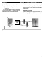
1
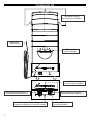
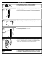
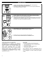
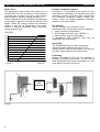
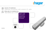
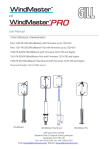
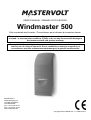
USER’S MANUAL / MANUEL D’UTILISATION
Windmaster 500
Grid connected wind inverter / Convertisseur pour éolienne à connexion réseau
This product must be protected externally against over voltages that may occur in noload and / or extreme wind conditions. Failure to do so may cause serious damage to
the inverter and will void product warranty.
Ce produit doit être protégé contre des surtensions pouvant se produire en cas de
vent fort ou s’il n’est pas connecté. Si ces conditions ne sont pas respectées, le
convertisseur peut être sérieusement endommagé et la garantie serait annulée.
MASTERVOLT
Snijdersbergweg 93,
1105 AN Amsterdam
The Netherlands
Tel.: +31-20-342 21 00
Fax: +31-20-697 10 06
www.mastervolt.com
Copyright © 2012 Mastervolt, v 1.2 March 2012
WINDMASTER 500
Ventilation openings
Ouvertures pour ventilation
Mains cord
Cordon réseau
LED indicator
Voyant indicateur
Ventilation opening
Ouverture pour ventilation
MultiContact plug positive (+)
Prise MultiContact positive (+)
Tab to release the mounting lock
Patte pour débloquer le verrou de montage
2
MultiContact plug negative (–)
Prise MultiContact négative (–)
Communication port
Port communication
INSTALLATION
• Read instructions on page 5 - 8 prior to installation.
• Lire les instructions pages 5 à 8 avant l’installation.
1
2
• Mark the position of the two mounting spots A and B by using the
mounting bracket.
• Marquer les deux points d’installation A et B à l’aide du support.
A
B
3
• If necessary, drill mounting holes at spots A and B.
• Si nécessaire, percer des trous de montage aux points A et B.
A
B
• Fix the mounting bracket to the wall.
• Fixer le support au mur.
4
A
B
5
6
• Place the Windmaster 500 over the mounting bracket and then
move it downwards until it is locked by the mounting bracket.
• Placer le Windmaster 500 sur le support de montage et le faire
glisser vers le bas jusqu’à ce qu’il soit bien positionné.
•
•
Check whether the Windmaster 500 is mounted in a secure way.
Vérifier que le Windmaster soit monté d’une manière sécurisée.
3
INSTALLATION
• Connect the string cabling to the Windmaster 500. If wind power is
sufficient, the LED indicator will illuminate red.
• Connecter le câble au Windmaster 500. Si le vent n’est pas suffisamment
fort, l’indicateur s’allume en rouge.
7
+
–
• Connect mains cord to the AC-wiring. Then switch on the grid. If wind
power is sufficient, the LED-indicator starts blinking red: the Windmaster
500 is starting up. This may last a few seconds.
• Connecter le cordon réseau au CA. Allumer ensuite le réseau. Si le vent est
suffisamment fort, l’indicateur clignote en rouge : le Windmaster 500 se met
en marche. Ceci peut durer quelques secondes.
8
AC
9
• After starting up, the LED-indicator starts blinking yellow.
• Après le démarrage, l’indicateur clignote en jaune.
• If wind power is too low, the indicator will extinguish
• Si le vent n’est pas suffisamment fort, l’indicateur s’éteint.
Product description and application
Congratulations for choosing the Mastervolt
Windmaster 500. The Windmaster 500 is a inverter
for grid connection of small wind turbines. The
design is based on the successful Soladin 600
Solar inverter. Windmaster 500 is an “OEM”
product and is sold as a part of a system through
selected system vendor. The product is to be
installed only with selected wind turbines. A system
is evaluation by Mastervolt is part of the
qualification process.
4
Unpacking
The delivery consists of the following parts:
• The Windmaster 500 with mounting bracket;
• This user’s manual;
• MultiContact “Pigtail” adapters (2x);
• Windmaster 500 PC-Link.
After unpacking, check the Windmaster 500 for
possible damage. Do not use the Windmaster 500
if it is damaged. If in doubt, contact your system
vendor.
ENGLISH
Safety
USERS MANUAL WINDMASTER 500
Max Input Voltage
Max Input Current
Nom Input Power
Max Short Circuit
150 V
8A
550 Wdc
12 A
• Contact an installer if the wind system does not
comply with the stipulations mentioned above.
Due to possible high voltages installation and
modification may only be carried out by a
qualified electrician who is familiar applicable
regulations and standards.
• Install the Windmaster 500 according to the
instructions stated in this manual.
• Be sure that the Windmaster 500 is
disconnected from the grid during installation.
This can be done by removing the fuse of the
corresponding branch circuit at the AC
distribution board.
• Connections and safety features must be
executed according to the locally applicable
regulations.
• The Windmaster 500 must be used in
accordance with the specifications as stated on
page 14.
• Never open the housing as high voltages may
be present inside!
Choosing the location to install
Obey the following stipulations during installation:
• The Windmaster 500 is suited for indoor use
only.
• Ambient temperature: 0... 50°C; (power derating
above 40°C), Humidity: 0-85% non condensing.
• Choose an optimal location to avoid long DC
and / or AC wiring and minimize energy loss.
• Do not install the Windmaster 500 in
environments with heavy dust development or
humidity.
• If the Windmaster 500 is installed in the
immediate vicinity of living areas, take into
account that it produces a slight noise level
when operating.
• Mount the Windmaster 500 vertically on a solid,
non-resonating, wall.
• Mount the Windmaster 500 in such a way that
obstruction of the airflow through the ventilation
openings is prevented.
• No objects must be located within a distance of
20 cm around the Windmaster 500.
• Multiple Windmaster 500 may be mounted next
to each other, not above each other. Minimum
spacing: 20 cm.
Things you need to install the Windmaster 500
Make sure you have all the parts you need to install
the Windmaster 500:
• The Windmaster 500;
• Two screws (with plugs) to mount the
Windmaster 500. Maximum diameter: 4.5 mm.
Use mounting materials which are suitable to
carry the weight of the Windmaster 500;
• Tools to fix the screws / bolts with plugs into the
wall (screwdriver, drilling machine, a set of drills,
a pencil).
Directions for installation
The Windmaster 500 is equipped with a so called
“anti-islanding safety device”. It ensures immediate
switch off in case of grid failure. European
countries maintain different regulations with regard
to anti-islanding devices and the supply of energy
back to the utility grid in general.
In some countries one single Windmaster 500 may
be connected to an existing electricity branch circuit
which is fused with 16 Amp. In other countries
different restrictions apply. Please acquaint yourself
with the local regulations on this issue!
The Windmaster 500 is sold as a part of a system.
Your system vendor will provide the Windmaster
500 with the appropriate settings for the local
electrical grid. Never connect the Windmaster 500
to a utility grid which is not suitable for use with the
apparatus!
During installation you can check by means of the
LED-indicator whether the installation is done
properly. This check can only be carried out when
sufficient wind power is present.
Although the Windmaster 500 is protected against
wrong polarity, the positive (+) and negative (–) of
the wind turbine connections should not be
exchanged.
Install the product according to the instructions
stated on page 3 and 4.
5
USERS MANUAL WINDMASTER 500
Monitoring
The Windmaster 500 has a communication port
that can be connected to the COM-port (RS232) of
a PC or laptop. Use the provided “Mastervolt PC–
link” interface and cable to set up a connection.
Part number
130391030
Description
PC-link Soladin/Windmaster,
incl. communication cable, 2m
NOTE: Communication is only possible
when sufficient wind power is present.
LED indicator
The operation mode of the Windmaster 500 is
displayed by means of a LED indicator at the front
side of the housing. In normal operation it flashes
LED Indication
LED is off
Meaning
Insufficient wind
power
No power from
the wind turbine
LED is off
• • • • •
Yellow blinking
▬
▬
▬
Slow blinking long
red pulses
▬▬▬▬▬▬
Fast blinking long
red pulses
▬▬▬▬▬▬▬▬
Uninterrupted red
• • • • •
Red blinking 1 time
Normal
operation
Reclosure time
•• •• •• ••
Red blinking 2 times
••• ••• •••
Red blinking 3 times
•••• ••••
Red blinking 4 times
••••• •••••
Red blinking 5 times
Turbine voltage
too high
AC grid voltage
too high
AC grid voltage
too low
Grid frequency
too high or too
low
Internal
temperature too
high
NTC error
••••••
Red blinking 6 times
•••••••
Red blinking 7 times
6
Restart time lag
No grid voltage
Turbine voltage
too low
ENGLISH
yellow: the faster the LED blinks yellow, the more
power is converted.
If the energy of the wind turbine is insufficient, the
Windmaster 500 switches off automatically. When
switched off, the LED indicator is off.
Failures
As long as the indication LED isn’t illuminated red,
no failure is detected: the Windmaster 500 is
operating normally. If an error occurs, it is detected
by the apparatus itself: the LED indicator turns red.
Consult the vendor, if you cannot solve the problem
by means of the table below.
NOTE: during low wind turbine voltage
detected by the Windmaster 500, indicated
by a red blinking LED indicator. This is a
normal situation.
What to do?
Nothing. The Windmaster 500 operates normally, but power
coming from the wind turbine is insufficient.
Consult an installer if the LED indicator is off while wind power is
sufficient. The wiring between the wind turbine and the
Windmaster 500 might be defective. Check for loose connections
or incorrect polarity.
Nothing. The Windmaster 500 operates normally. The faster the
LED blinks yellow, the more power is converted.
Nothing. After the Windmaster 500 was (re)connected to the AC
grid, it checks the quality of the AC grid before it starts operating
normally. This may take up to 5 minutes.
Nothing. A system check is carried out during startup. This may
take up to 5 seconds before the Windmaster 500 starts operating
normally.
Plug the AC-plug of the Windmaster 500 into the wall socket;
check the fuse in the meter cupboard.
Nothing; normal condition during low wind conditions.
Consult an installer if the problem remains while strong wind
conditions exist.
Error in the Wind turbine system. Is the wind turbine qualified for
use in accordance with Windmaster 500?
Consult an installer. Error in the installation. Is the wind turbine
qualified for use in accordance with Windmaster 500?
Check the grid connection.
Check the grid connection.
Check the grid connection.
Air flow of the Windmaster 500 must not be obstructed. If the
problem remains, switch off the Windmaster 500 by removing the
fuse from the meter cupboard and consult your system vendor.
Consult your system vendor for repair of a defective safety device
in the Windmaster 500.
ENGLISH
Operation
After installation the Windmaster 500 will switch on
automatically if wind power is sufficient. The
Windmaster 500 operates automatically: there is no
need for user adjustment or control. The
Windmaster 500 has no ON/OFF switch; If
necessary remove the fuse from the AC distribution
board to switch it off. Do not disconnect the
MultiContact plugs during operation of the
Windmaster 500! No specific maintenance is
required. If necessary, use a soft clean cloth to
clean the Windmaster 500. Never use any liquids,
acids and/or scourers.
Decommissioning
First remove the Fuse from the AC distribution
board before you disconnect the MultiContact
plugs. Now the Windmaster 500 can be demounted
in a safe way:
1. Push on the lower tab of the mounting bracket
to release the mounting lock.
2. Lift the Windmaster 500 upwards for
approximately 1 cm.
3. Move the Windmaster 500 straight from the
wall.
USERS MANUAL WINDMASTER 500
Warranty and Support
The inverter is supplied with a 2-year standard
product warranty. Other warranty agreements
between system vendor and Mastervolt may apply.
First line service and support is performed by the
system vendor. Defects caused by DC or AC over
voltage, out-of-specification short circuit current,
direct or induced lightning and surges as well as
cost of travel, installation and energy loss are
excluded from product warranty.
Liability
Mastervolt cannot be held liable for:
• Possible errors in this included manual and the
consequences of these.
• Use that is inconsistent with the purpose of the
product.
7
USERS MANUAL WINDMASTER 500
Power Curve
The Windmaster 500 converts DC power from a
wind turbine to the AC grid based. This conversion
is based upon a linear curve with a start voltage
and a maximum operating voltage (see figure 1).
These parameters may be adjusted and optimized
by the system vendor for use with a particular wind
turbine. When DC voltage reaches the threshold
voltage to start up the Windmaster, the inverter
starts a 5 seconds countdown before delivering
energy to the AC grid.
Pdc [W]
550
500
450
ENGLISH
Example installation diagram
See figure 2. This drawing is not specific for any
wind turbine or installation. It is provided as a basic
reference, showing necessary major components
and installation sequence. Please contact your
system vendor for detailed installation drawings,
specific for you wind turbine.
DC interface
The DC interface is for protection of the
Windmaster 500, and should provide the following:
• Surge protection (if applicable);
• Over voltage protection, max. 150VDC (*);
• Disconnection switch (if applicable).
(*) Mechanical either electrical OVP may be
integrated in the wind turbine
400
Grounding
The Windmaster 500 is a class II device with
galvanic isolation between DC and AC. The
inverter doesn’t need to be grounded. Grounding of
the Wind turbine however is recommended.
350
300
250
200
150
100
50
10 20 30 40 50 60 70 80 90 100 110 120 130 140150
Figure 1
Udc [V]
DC
Interface
Figure 2
8
Paralleling
Multiple Windmasters 500 can be operated in
parallel to increase output power. The DC side of
each Windmaster 500 must be protected by a 10A
(slow blow) fuse (refer to figure 2).
ENGLISH
SPECIFICATIONS
Model
Part number:
Manufacturer:
Operating temperature:
Storage temperature:
Relative humidity:
Protection degree:
Safety class:
Galvanic isolation
Dimensions (H x W x D):
Weight:
Enclosure:
Mounting
Windmaster 500
140000500
Mastervolt, Amsterdam, the Netherlands
0°C to 40°C (full power)
-20°C to 70 °C
Max. 85%, non condensing (electronics have anti-moisture coating)
IP20 (for indoor use)
Class II Double insulated
Class II HF transformer
365 x 143 x 75 mm (including connectors)
Approx. 2 kg.
UL 5V fire retardant ABS/PC
Wall mounting bracket included
Input (DC)
Nominal power:
Operating voltage range:
Full power voltage range:
Max current:
Max short current:
Start-up power:
Connectors:
550 W DC
35 -150 V DC
65 -125 V DC
8A
12 A
1W
MultiContact 4mm type connectors ; adapters are included
Paralleling
Multiple units can be operated in parallel to increase output power
The DC-input of each unit must be protected by a 10 A DC (slow blow) fuse
Output (AC)
Voltage:
Nominal power:
Nominal current:
Fuse:
Frequency:
Cos phi:
Stand-by power:
Maximum efficiency:
Mains cord:
230V (185 V - 264 V)
525 W
2,25 A
3,15 A -T
50 Hz (48-52 Hz)
0,99
< 0,05 Wac
93%
1,8 meter of AC wire
Safety Functions
Anti-Islanding
Over temperature
Polarity
Surges
Voltage- and frequency window; frequency shift G83 compliant
Power derating at > 40 °C; switch off at internal over temperature
Protected against inverse polarity
Protected against AC and DC surges caused by indirect lightning strike
User Interface
Front indicator
Normal operation
Fault indication
Communication
Dual color (yellow/red)
Yellow blinking (faster blinking = higher power)
Red flashing (6 different codes)
PC-Link adapter and cable for RS-232 communication included. PC software
downloadable from www.mastervolt.com
National grid connection regulations
Approvals:
G83 (GB); NTA 8493 (Netherlands)
Country compatibility
Standard suitable for all 230V / 50 Hz countries. Country specific settings
programmable. External ENS may be required for some countries
(contact your local distribution network operator for local grid connection requirements)
9
MANUEL D’UTILISATION WINDMASTER 500
Description et application du produit
Nous vous félicitons d’avoir choisi le Windmaster
500 de Mastervolt. Le Windmaster 500 est un
convertisseur pour connexion réseau avec des
petites éoliennes. Il est basé sur la même
conception que le Soladin 600 Solaire. Le
Windmaster 500 est un produit destiné aux ‘OEM’ et
est vendu en tant qu’élément d’un système. Il doit
être installé uniquement avec certaines éoliennes.
Le système doit être approuvé par Mastervolt.
Déballage
La livraison comprend les pièces suivantes :
• Le Windmaster 500 avec support de montage
• Ce manuel d’utilisation
• 2 adaptateurs MultiContact ‘Pigtails’
• PC Link Windmaster 500
Après déballage, vérifiez que le Windmaster 500
n’ait pas été abîmé dans le transport. Ne l’utilisez
pas s’il est endommagé. En cas de doute, contactez
votre fournisseur.
Sécurité
Tension entrée max
Intensité entrée max
Puissance entrée nom
Court circuit max
150 V
8A
550 Wcc
12 A
• Contactez un installateur si le système ne répond
pas aux indications ci-dessus. A cause des
risques de surtensions, l’installation et les
modifications ne doivent être effectuées que par
un électricien qualifié et qui connait les normes
en vigueur.
• Installez le Windmaster 500 selon les instructions
décrites dans ce manuel.
• Assurez-vous que le Windmaster 500 est
déconnecté du réseau pendant l’installation.
Vous pouvez pour cela retirer le fusible
correspondant sur le tableau de distribution CA.
• Les connexions et les procédures de sécurité
doivent respecter les normes en vigueur.
• Le
Windmaster
500
doit
être
utilisé
conformément aux spécifications mentionnées
page 14.
• N’ouvrez jamais le boîtier à cause des
surtensions !
Choix du lieu d’installation
Suivez les indications ci-dessous pendant
l’installation:
• Le Windmaster 500 doit être installé à l’intérieur
uniquement.
• Température ambiante : de 0 à 50°C (diminution
de puissance au-dessus de 40°C), humidité : 085% sans condensation.
• Choisissez un endroit optimal pour l’installation
afin de réduire la longueur des câbles CC et CA
et de minimiser ainsi les pertes.
10
FRANÇAIS
• Ne pas installer le Windmaster 500 dans des
environnements avec beaucoup de poussière et
d’humidité.
• Si le Windmaster 500 est installé à proximité de
lieux de vie, tenez compte du fait qu’il produit un
léger bruit lorsqu’il est en fonctionnement.
• Montez le Windmaster 500 verticalement sur un
mur solide, sans résonance.
• Montez le Windmaster 500 de manière à éviter
l’obstruction des ouvertures de ventilation.
• Aucun objet ne doit être situé à moins de 20 cm
du Windmaster 500.
• Plusieurs Windmaster 500 peuvent être montés à
côté les uns des autres, mais pas les uns SUR
les autres. Espace minimum entre les appareils :
20 cm.
Ce dont vous avez besoin pour installer le
Windmaster 500
Assurez-vous que vous avez toutes les pièces
nécessaires pour installer le Windmaster 500 :
• Le Windmaster 500
• Deux vis pour monter le Windmaster 500.
Diamètre maximum : 4.5 mm. Utilisez du matériel
de montage pouvant supporter le poids du
Windmaster 500.
• Outils pour fixer les vis dans le mur (tournevis,
perceuse, crayon).
Instructions d’installation
Le Windmaster 500 est équipé d’une sécurité antiilôtage. Il s’arrête automatiquement en cas de
défaut du réseau. Les pays européens n’ont pas
tous les mêmes normes à ce sujet et au sujet de
l’alimentation de secours en cas de problème
réseau en général.
Dans certains pays un seul Windmaster 500 peut
être connecté à un circuit électrique existant,
protégé par un fusible de 16A. Dans d’autres pays,
différentes
restrictions
sont
appliquées.
Renseignez-vous auprès des autorités locales.
Le Windmaster 500 est vendu en tant qu’élément
d’un système. Votre fournisseur vous fournira le
Windmaster 500 avec les réglages adaptés au
réseau. Ne connectez jamais le Windmaster 500 à
un réseau non adapté à l’utilisation de l’appareil.
Pendant l’installation vous pouvez vérifier par
l’indicateur si tout est fait correctement. Cette
vérification ne peut être effectuée que si le vent
souffle suffisamment. Bien que le Windmaster 500
soit protégé contre une mauvaise polarité, le positif
(+) et le négatif (-) de l’éolienne ne doivent pas être
intervertis. Installez le produit selon les instructions
sur les pages 3 et 4.
FRANÇAIS
MANUEL D’UTILISATION WINDMASTER 500
Monitoring
Le Windmaster 500 est muni d’un port de
communication qui peut être connecté au port COM
(RS232) d’un PC ou ordinateur portable. Utilisez
l’interface Mastervolt PC link et le câble pour
effectuer la connexion.
Référence
130391030
Désignation
PC Link Soladin/Windmaster avec
câble de communication 2m
NOTE: la communication n’est possible que
lorsque le vent souffle suffisamment fort.
Voyant indicateur
Le mode fonctionnement du Windmaster 500 est
affiché par un voyant sur la face avant du boîtier. En
fonctionnement normal, il clignote en jaune : plus
Indication voyant
Led éteint
Signification
Pas assez de vent
Led éteint
L'éolienne ne
produit pas
• • • • •
Clignote jaune
▬
▬
▬
Pulsations rouges
clignotant lentement
▬▬▬▬▬▬
Pulsations rouges
clignotant rapidement
▬▬▬▬▬▬▬▬
Rouge ininterrompu
• • • • •
Clignote rouge 1 fois
•• •• •• ••
Clignote rouge 2 fois
••• ••• •••
Clignote rouge 3 fois
•••• ••••
Clignote rouge 4 fois
••••• •••••
Clignote rouge 5 fois
••••••
Clignote rouge 6 fois
Fonctionnement
normal
Temps de
redémarrage
Délai de
redémarrage
Pas de tension
réseau
Tension éolienne
trop basse
Tension éolienne
trop haute
Tension réseau CA
trop haute
Tension réseau CA
trop basse
Fréquence réseau
trop haute ou trop
basse
Température
interne trop haute
Erreur NTC
•••••••
Clignote rouge 7 fois
vite le voyant clignote, et puis il y a de puissance
convertie.
Si l’énergie de l’éolienne est insuffisante, le
Windmaster 500 s’arrête automatiquement. Lorsqu’il
est arrêté, le voyant est éteint.
Erreurs
Tant que le voyant n’est pas allumé en rouge,
aucune erreur n’est détectée : le Windmaster 500
fonctionne normalement. Si une erreur se produit,
elle est détectée par l’appareil : le voyant s’allume
en rouge. Si vous ne parvenez pas à régler le
problème à l’aide du tableau ci-dessous, consultez
votre fournisseur.
NOTE: en cas de vent faible, la tension est
détectée par le Windmaster 500 et le voyant
clignote en rouge. Ceci est une situation
normale.
Que faire?
Rien. Le Windmaster 500 fonctionne normalement, mais la
puissance de l'éolienne est insuffisante.
Consultez un installateur si le voyant est éteint alors que le vent
souffle suffisamment. Le câblage entre l'éolienne et le
Windmaster 500 est peut être défectueux. Vérifiez les
connexions ou inversion de polarité.
Rien. Le Windmaster 500 fonctionne normalement. Plus vite le
voyant clignote, plus de puissance est convertie.
Rien. Après que le Windmaster 500 ait été reconnecté au
réseau CA, il vérifie la qualité du réseau CA avant de se
remettre à fonctionner normalement. Cela peut prendre environ
5 minutes.
Rien. Une vérification de système est effectuée au moment du
démarrage. Cela peut prendre 5 secondes, avant que le
Windmaster fonctionne à nouveau normalement.
Connectez la prise CA du Windmaster 500 au mur, vérifiez le
fusible sur le tableau.
Rien; conditions normales s'il y a peu de vent. Consultez un
installateur si le problème persiste alors que le vent souffle fort.
Problème avec l'éolienne. Est-elle adaptée à une utilisation
avec le Windmaster 500?
Consultez un installateur. Problème d'installation. L'éolienne
est-elle adaptée à une utilisation avec le Windmaster 500?
Vérifier la connexion réseau.
Vérifier la connexion réseau.
Vérifier la connexion réseau.
Les ventilations du Windmaster 500 sont peut être obstruées. Si
le problème persiste, arrêter le Windmaster 500 en retirant le
fusible du tableau et contactez votre fournisseur.
Consultez votre fournisseur pour une réparation.
11
MANUEL D’UTILISATION WINDMASTER 500
Fonctionnement
Après installation le Windmaster 500 se met en
route automatiquement si le vent souffle
suffisamment fort. Le Windmaster 500 fonctionne
automatiquement : pas besoin d’ajustement ou de
monitoring. Le Windmaster 500 n’a pas de bouton
marche/arrêt ; si nécessaire, retirez le fusible du
tableau de distribution CA pour l’arrêter. Ne
déconnectez pas les prises MultiContact pendant
le fonctionnement du Windmaster 500 ! Aucun
entretien spécifique n’est requis. Si nécessaire,
utiliser un chiffon propre pour le nettoyer. N’utilisez
jamais de liquides, d’acides et/ou de produits à
récurer.
Démontage
Retirez d’abord le fusible du tableau de distribution
CA avant de déconnecter les prises MultiContacts.
Le Windmaster 500 peut maintenant être
démonté :
1. Appuyez sur la patte en bas du support de
montage pour le déverrouiller.
2. Lever le Windmaster 500 d’environ 1 cm.
3. Retirer le Windmaster 500 du mur.
Garantie et support
Le convertisseur est fourni avec une garantie de
deux ans. D’autres accords entre le fournisseur et
Mastervolt peuvent s’appliquer. Le premier support
technique est effectué par le fournisseur du
système. Les défauts causés par une surtension
CA ou CC, un court circuit hors spécifications, des
pics de tension ou la foudre, des frais de
déplacement, d’installation ou des pertes de
puissance ne sont pas couverts par la garantie.
Responsabilité
Mastervolt ne peut être tenue pour responsable
pour :
• De possibles erreurs contenues dans ce manuel
et leurs consequences.
• Une utilisation du produit non conforme aux
spécifications.
12
FRANÇAIS
Courbe de puissance
Le Windmaster 500 convertit la puissance CC
d’une éolienne vers le réseau CA. Cette conversion
est basée sur une courbe linéaire avec une tension
de démarrage et une tension de fonctionnement
maximum (voir schéma 1). Ces paramètres
peuvent être ajustés et optimisés par le fournisseur
du système pour une utilisation avec une éolienne
en particulier. Lorsque la tension CC atteint la
tension seuil pour démarrer le Windmaster, celui-ci
démarre un compte à rebours de 5 secondes avant
de fournir l’énergie au réseau.
Pdc [W]
550
500
450
400
350
300
250
200
150
100
50
10 20 30 40 50 60 70 80 90 100 110 120 130 140150
Figure 1
Udc [V]
Exemple d’installation
Voir schéma 2. Ce schéma n’est pas spécifique à
une éolienne ou une installation précise. Il est
fourni comme référence de base, indiquant les
principaux éléments nécessaires et la séquence
d’installation. Contactez votre fournisseur pour des
schémas d’installation spécifiques à votre éolienne.
FRANÇAIS
MANUEL D’UTILISATION WINDMASTER 500
Interface CC
L’interface CC est là pour protéger le Windmaster
500, et devrait fournir ce qui suit :
• Protection contre les pics de tension ;
• Protection contre les surtensions, max
150VCC (*) ;
• Interrupteur de déconnexion (si applicable).
(*) Protection mécanique ou électrique contre des
surtensions peut être intégrée dans l’éolienne.
Mise à la terre
Le Windmaster 500 est un appareil de classe II
avec une isolation galvanique entre le CC et le CA.
Le convertisseur n’a pas besoin d’une mise à la
terre. La mise à la terre de l’éolienne est cependant
recommandée.
Installation en parallèle
Plusieurs Windmaster 500 peuvent fonctionner en
parallèle afin d’augmenter la puissance. Le côté
CC de chaque Windmaster 500 doit être protégé
par un fusible de 10A (voir schéma 2).
Interface
CC
Figure 2
13
SPÉCIFICATIONS
Modèle
Référence
Fabricant
Température de fonction.
Température de stockage
Humidité relative
Degré de protection
Classe de sécurité
Isolation galvanique
Dimensions (hxlxp)
Poids
Boîtier
Montage
Entrée (CC)
Puissance nominale
Gamme de tension de
fonctionnement
Gamme de tension pleine
puissance
Intensité max
Intensité court circuit
Puissance démarrage
Connecteurs
Mise en parallèle
FRANÇAIS
Windmaster 500
140000500
Mastervolt, Amsterdam, Pays-Bas
0°C à 40°C (pleine puissance)
-20°C à 70°C
Max 85%, sans condensation (les composants électroniques sont recouverts d’un
vernis anti-moisissure)
IP20 (pour utilisation à l’intérieur)
Classe II double isolation
Classe II transformateur HF
365 x 143 x 75 mm, connecteurs inclus
Environ 2 kg
UL 5V retardant le feu ABS/PC
Au mur avec le support
550 WCC
35-150 VCC
65-125 VCC
8A
12 A
1W
MultiContact 4 mm ; adaptateurs inclus
Plusieurs unités peuvent fonctionner en parallèle pour augmenter la puissance.
L’entrée CC de chaque unité peut être protégée par un fusible 10A CC.
Sortie (CA)
Tension
Puissance nominale
Intensité nominale
Fusible
Fréquence
Cos phi
Puissance stand by
Rendement max
Cordon réseau
230V (185 V - 264 V)
525 W
2.25 A
3.15A –T
50 Hz (48-52 Hz)
0.99
< 0.05 Wca
93%
1.8 m de câble CA
Fonctions sécurité
Anti ilôtage
Température élevée
Polarité
Crêtes
Gamme de tension et fréquence ; conforme à la norme G83
Diminution de puissance >40°C ; arrêt en cas de température interne trop élevée
Protégé contre les inversions de polarité
Protégé contre les crêtes CA et CC causé par des coups de foudre indirects
Interface utilisateur
Indicateur face avant
Fonctionnement normal
Indication d’erreur
Communication
Bicolore (jaune/vert)
Clignote jaune (clignotement rapide=puissance plus élevée)
Clignote rouge (6 codes différents)
Adaptateur PC Link et câble de communication RS232 inclus. Logiciel PC
téléchargeable sur www.mastervolt.fr
Normes de connexion réseau
Conformité
G83 (GB) ; NTA 8493 (Pays-Bas)
Compatibilité pays
S’adapte à tous les pays en 230V / 50Hz. Des réglages spécifiques sont nécessaires
pour certains pays. Carte ENS externe nécessaire pour certains pays (contactez votre
distributeur pour la connexion au réseau local).
14
DIMENSIONS
All dimensions are in mm.
15
EC DECLARATION OF CONFORMITY
Manufacturer: Mastervolt
Address:
Snijdersbergweg 93
1105 AN Amsterdam
The Netherlands
Herewith declares that:
Product:
Windmaster 500
Is CE-marked and complies with the following standards:
EMC directive
Environment:
89/336/EEC
residential, commercial and light industrial
Emission
Emission - class B:
harmonic current emission:
EN 55022: 1998
EN 61000-3-2: 2000
Immunity
Generic immunity standard:
Electrostatic discharge (ESD):
Radiated EMC:
Electrical fast transients (EFT) :
Surge transient :
Conducted RF disturbances :
Voltage dips and short interrupts :
Digital radio telephones :
EN 61000-6-2: 2001
EN 61000-4-2: 1995
EN 61000-4-3: 1996
EN 61000-4-4: 1995
EN 61000-4-5: 1995
EN 61000-4-6: 1996
EN 61000-4-11: 1994
ENV 50204: 1995
Safety
Low Voltage directive :
Electrical safety :
2006/95/EC
EN 60950 : 2003
EN 62109-1 : 2010
Amsterdam,
Ing. D.R. Bassie
Product Manager
© Mastervolt BV, Snijdersbergweg 93, 1105 AN Amsterdam, Netherlands
Tel: + 31-20-3422100 Fax: + 31-20-6971006 Email: [email protected]