1
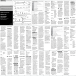
biddle KLV handl 2002 • 237152
NL
D
GB
F
25-03-2003
09:32
Pagina 1
Cassette-Luchtverwarmers
Kassetten-Lufterwärmer
Cassette Air Heaters
Aérothermes-Cassettes
Model KLV/KLV E
Modell KLV/KLV E
Model KLV/KLV E
Modèle KLV/KLV E
NL
D
Handleiding Installatie - Onderhoud
Anleitung Montage - Wartung
GB
F
Manual Installation - Maintenance
Manuel d’utilisation Installation - Maintenance
biddle KLV handl 2002 • 237152
25-03-2003
09:32
Pagina 2
NL
Inhoudsopgave
GB
Contents
1.
2.
3.
4.
5.
6.
7.
8.
9.
10.
Algemeen . . . . . . . . . . . . . . . . . . . . . . . . . . . . . . . . . . . . 3
Controle bij aflevering. . . . . . . . . . . . . . . . . . . . . . . . . . . 4
Montage . . . . . . . . . . . . . . . . . . . . . . . . . . . . . . . . . . . . . 4
C.V. aansluitingen. . . . . . . . . . . . . . . . . . . . . . . . . . . . . . . 5
Aansluiten elektrische voeding . . . . . . . . . . . . . . . . . . . . 6
Montage roosterpaneel . . . . . . . . . . . . . . . . . . . . . . . . . . 7
Onderhoud . . . . . . . . . . . . . . . . . . . . . . . . . . . . . . . . . . . 8
Wijzigen standaard instellingen . . . . . . . . . . . . . . . . . . . . 9
Storingen. . . . . . . . . . . . . . . . . . . . . . . . . . . . . . . . . . . . 10
Technische gegevens . . . . . . . . . . . . . . . . . . . . . . . . . . . 11
1.
2.
3.
4.
5.
6.
7.
8.
9.
10.
General . . . . . . . . . . . . . . . . . . . . . . . . . . . . . . . . . . . . . . 3
Delivery check . . . . . . . . . . . . . . . . . . . . . . . . . . . . . . . . 4
Installation . . . . . . . . . . . . . . . . . . . . . . . . . . . . . . . . . . . 4
Pipework connections . . . . . . . . . . . . . . . . . . . . . . . . . . . 5
Electrical connections . . . . . . . . . . . . . . . . . . . . . . . . . . . 6
Grille panel installation . . . . . . . . . . . . . . . . . . . . . . . . . . 7
Maintenance . . . . . . . . . . . . . . . . . . . . . . . . . . . . . . . . . . 8
Modification of standard speeds . . . . . . . . . . . . . . . . . . . 9
Troubleshooting . . . . . . . . . . . . . . . . . . . . . . . . . . . . . . 10
Technical specifications . . . . . . . . . . . . . . . . . . . . . . . . . 11
Raadpleegt u voor installatie en bediening van de tiptoetsschakelaar,
de handleiding "Tiptoetsschakelaar".
For installation and operation of the touch control, please
consult ”Touch Control” manual.
D
Inhaltsverzeichnis
F
Sommaire
1.
2.
3.
4.
5.
6.
7.
8.
9.
10.
Allgemeines . . . . . . . . . . . . . . . . . . . . . . . . . . . . . . . . . . . 3
Kontrolle bei Ablieferung. . . . . . . . . . . . . . . . . . . . . . . . . 4
Montage . . . . . . . . . . . . . . . . . . . . . . . . . . . . . . . . . . . . . 4
PWW-Anschlüsse . . . . . . . . . . . . . . . . . . . . . . . . . . . . . . 5
Elektrischer Anschluß . . . . . . . . . . . . . . . . . . . . . . . . . . . 6
Montage Gitter . . . . . . . . . . . . . . . . . . . . . . . . . . . . . . . . 7
Wartung . . . . . . . . . . . . . . . . . . . . . . . . . . . . . . . . . . . . . 8
Änderung der Standarddrehzahlen . . . . . . . . . . . . . . . . . 9
Störungen . . . . . . . . . . . . . . . . . . . . . . . . . . . . . . . . . . . 10
Technische Daten . . . . . . . . . . . . . . . . . . . . . . . . . . . . . 11
1.
2.
3.
4.
5.
6.
7.
8.
9.
10.
Généralités . . . . . . . . . . . . . . . . . . . . . . . . . . . . . . . . . . . 3
Vérification à la livraison . . . . . . . . . . . . . . . . . . . . . . . . . 4
Installation . . . . . . . . . . . . . . . . . . . . . . . . . . . . . . . . . . . 4
Raccordement eau chaude . . . . . . . . . . . . . . . . . . . . . . . 5
Alimentation électrique . . . . . . . . . . . . . . . . . . . . . . . . . . 6
Installation du panneau inférieur . . . . . . . . . . . . . . . . . . 7
Maintenance . . . . . . . . . . . . . . . . . . . . . . . . . . . . . . . . . . 8
Modification des débits standard . . . . . . . . . . . . . . . . . . . 9
Pannes. . . . . . . . . . . . . . . . . . . . . . . . . . . . . . . . . . . . . . 10
Caracteristiques techniques. . . . . . . . . . . . . . . . . . . . . . 11 .
Für das Installieren und Bedienen des Tipptasten-schalters ziehen Sie bitte die
Anleitung "Tipptastenschalter" zu Rate.
Pour l’installation et la commande du boîtier de contrôle digital, se reporter
au manuel d’utilisation, ”Boîtier de contrôle digital”.
2
biddle KLV handl 2002 • 237152
NL
D
25-03-2003
09:32
Pagina 3
Algemeen
Allgemeines
NL De cassetteluchtverwarmer is bedoeld voor:
- het verwarmen van lucht;
- inbouw in een systeemplafond van 600x600 mm of 600x1200 mm
(eventueel vrijhangend aan het plafond);
- montage op hoogtes van1,8 tot 3,5 m (vloer tot uitblaasrooster).
De fabrikant raadt elk ander gebruik af. Een dergelijk gebruik valt derhalve
niet onder diens verantwoordelijkheid.
D Der Kassetten-Lufterwärmer eignet sich für:
- das Heizen von Luft;
- Deckenmontage in einer Systemdecke von 600x600 mm oder 600x1200
mm (oder direkte Montage an Betondecke);
- Aufhängung auf Höhen von 1,8 bis 3,5 m (Boden bis Ausblasgitter).
Der Hersteller rät von jeder anderen Anwendung ab und übernimmt dann
auch keine Verantwortung für eine derartige Anwendung.
1
GB
F
General
Généralités
GB The cassette air heater is intended for:
- heating air;
- installation in a false ceiling of 600x600 mm or 600x1200 mm (or mounted
directly on to ceiling slab);
- suspension at heights from 1.8 to 3.5 m (floor to discharge grille).
The manufacturer advises against any other use and, therefore, will not take
responsibility for any such use.
F
-
L’aérotherme-cassette est destiné à:
réchauffer un volume d’air;
être installé en remplacement d’une dalle de faux plafond 600x600 mm ou
600x1200 mm (ou monté en version apparente au plafond);
être suspendu entre 1,8 et 3,5 m (du sol à la grille de soufflage).
Le fabricant déconseille toute utilisation contraire, une telle utilisation ne
tombe pas sous sa responsabilité.
3
biddle KLV handl 2002 • 237152
25-03-2003
09:32
Controle bij aflevering
Kontrolle bei Ablieferung
NL
D
Pagina 4
2
1.
Delivery check
Vérification à la livraison
GB
F
2.
KLV 2
KLV 1
NL
Montage
D
Montage
3
GB
Installation
F
Installation
2.
1.
A
B
x = 610mm (KLV 1) / 1210mm (KLV 2)
y = 750 - 830mm
NL
D
GB
F
A=
A=
A=
A=
flamco-rails
Profil-Schiene
unistrut type rails
rails flamco
B=
B=
B=
B=
montagerail (bijgeleverd)
Montageschiene (mitgeliefert)
mounting brackets (supplied with unit)
rails de fixation (fourni avec l’appareil)
NL
D
GB
F
Verplaats toestel met minimaal 2 personen.
Montieren Sie das Gerät mit mindestens 2 Personen.
Appliance should be installed by at least two persons.
Déplacer l'appareil au moins avec deux personnes.
4
biddle KLV handl 2002 • 237152
NL
D
25-03-2003
09:32
Montage
Montage
Pagina 5
3
NL
D
F
Installation
Installation
4.
3.
NL
D
GB
F
GB
Na ophanging altijd borgen
Nach Montage immer sichern
Always fasten safety brackets
Toujours bloquer les pattes de sécurité
C.V. aansluitingen (alleen KLV)
PWW-Anschlüsse (nur KLV)
4
GB
F
Pipework connections (only KLV)
Raccordement eau chaude (seulement KLV)
1.
5
biddle KLV handl 2002 • 237152
NL
D
25-03-2003
09:32
Pagina 6
Aansluiten elektrische voeding
Elektrischer Anschluß
230 VAC
KLV
NL
D
GB
F
5
GB
F
Electrical connections
Alimentation électrique
1.
KLV E
Houdt ruimte voor het verwijderen van stekker uit stopcontact.
Lassen Sie Raum für das Entfernen des Steckers aus der Steckdose.
Allow space for removing plug from wall socket.
Permettre l’acces pour débrancher la prise.
2.
KLV E
NL Geen kabels e.d. op toestel leggen. Bovenkant kan heet worden.
D Keine Gegenstände wie Kabel auf den oberen Teil des Gerätes
legen. Die Oberseite kann heiß werden.
GB Don’t place electric cables or other items on the top of the unit, as
it is liable to get hot.
F Température élevée: ne RIEN poser au dessus de l’appareil!
3.
KLV E
NL Neem een alpolige schakelaar met een contactscheiding van minimaal 3 mm op in het circuit.
D Mehrpoligen Reparaturschalter mit einer Kontakttrennung von minimal 3 mm vorsehen.
GB Incorporate an all-pole switch with a minimum contact separation of
3 mm in the circuit; this appliance must be earthed.
F Protéger l’alimentation électrique avec un interrupteur assurant une
coupure omnipolaire avec une séparation des contacts d’au moins 3 mm.
6
biddle KLV handl 2002 • 237152
NL
D
25-03-2003
Montage roosterpaneel
Montage Gitter
09:32
Pagina 7
6
GB
F
Grille panel installation
Installation du panneau inférieur
7
biddle KLV handl 2002 • 237152
NL
D
1.
25-03-2003
Onderhoud (alleen KLV)
Wartung (nur KLV)
09:32
Pagina 8
7
GB
F
Maintenance (only KLV)
Maintenance (seulement KLV)
2.
NL
D
GB
F
Batterij kan heet en scherp zijn.
Die Batterie kann heiß und scharfkantig sein.
The battery may be hot and sharp.
La batterie est coupante et peut être chaude.
3.
NL Filter met behulp van de stofzuiger regelmatig reinigen (afhankelijk van gebruikssituatie).
D Filter regalmäßig mit einem Staubsauger reinigen (Reinigungszeitraum is abhängig von der
Nutzungsdauer und -Situation).
GB Vacuum clean filter regularly (dependent on situation).
F Nettoyer fréquemment le filtre avec un aspirateur (dépend de la fréquence d'utilisation).
8
biddle KLV handl 2002 • 237152
NL
D
25-03-2003
09:32
Pagina 9
Wijzigen standaardinstellingen 8
Änderung der Standardeinstellungen
GB
F
Modification of standard settings
Modification de la mise au point d'origine
3.
1.
KLV E
KLV
= 200 V
NL
D
GB
F
2.
NL
D
GB
Interface
F
= 155 V
= 115 V
verplaats fastons
Kabelanschlüsse neu anordnen
move required spade connectors
déplacer les cosses souhaitées
Voor het wijzigen van standaardinstellingen op de interface, zie handleiding 'Tiptoetsschakelaar' (meegeleverd),
Um die Standardeinstellung auf dem Interface zu ändern, lesen Sie bitte
die Anleitung 'Tipptastenschalter' (wird mitgeliefert).
For modifications on the standard settings of the interface please consult 'Touch Control' manual (supplied with unit),
Pour la modification de la mise au point d'origine de l'interface, se
reporter au manuel d'utilisation 'Boîtier de contrôle digital'
(fourni avec l'appareil).
9
biddle KLV handl 2002 • 237152
NL
D
25-03-2003
09:32
Storingen
Störungen
Pagina 10
9
GB
F
Troubleshooting
Pannes
NL 1. Controleer elektrische aansluiting.
2. Alleen KLV E: Reset maximaalthermostaat (zie onder).
Deze schakelt het verwarmingselement uit bij gevaarlijk hoge temperatuur. Waarschuw uw installateur.
D 1. Kontrollieren Sie den elektrischen Anschluß.
2. Nur KLV E: Drücken Sie den Reset-Schalter des Thermokontakts (siehe unten).
Der Reset-Schalter schaltet das Gerät bei gefährlich hohen Temperaturen aus. Informieren Sie ihren Installateur.
GB 1. Check the electrical connection.
2. Only for KLV E: Reset thermal contact protection (see below).
This switches off the heating elements at dangerously high temperatures.Warn your installer.
F 1. Contrôler l'alimentation électrique de l'appareil
2. Seulement pour le KLV E ré-enclencher le thermostat de surchauffe (schéma ci-dessous).
Le thermostat de surchauffe s’enclenche lorsqu'une température maximale est atteinte. Consulter votre installateur.
1.
NL Reset knopje
D Reset Schalter
KLV E
GB
F
Reset button
Bouton de reset
2.
”CLICK”
10
biddle KLV handl 2002 • 237152
NL
D
25-03-2003
09:32
Pagina 11
10
Technische gegevens
Technische Daten
NL
max. plafondhoogte
luchtverplaatsing
max. Deckenhöhe
1
2
3
verwarmingscapaciteit
1
2
3
Technical specifications
Caracteristiques techniques
max. ceiling height
KLV E-1
KLV 2
KLV E-2
hauteur sousplafond max.
m
3,5
3,5
3,5
3,5
débit d’air
1
2
3
m3/h
460
665
865
460
665
865
920
1330
1730
920
1330
1730
1
2
3
kW
6,6
8,2
9,6
3
3/6
6/9
13,2
17,4
20,2
6
6/12
12/18
air volume
Heizleistung
heating capacity
1
2
3
capacité de
chauffage
noise level
niveau sonore 1
2
3
dB(A)
39
48
54
39
48
54
40
49
55
40
49
55
1
2
3
Geräuschpegel
1
2
3
1
2
3
KLV 1
Luftvolumenstrom 1
2
3
1
2
3
geluiddruk
F
F
GB
D
GB
1
2
3
max. waterhoeveelheid
max.Wassermenge
max. water
flow rate
débit d’eau max.
m3/h
0,44
/
0,93
/
max. waterzijdig
drukverlies
max. wasserseitiger
Druckverlust
max. water
resistance
perte de charge
de l’eau max.
kPa
8
/
10
/
spanning
Spannung
voltage
tension
V
230
400/230
230
400/230
max. vermogen
motoren
max. Leistungsaufnahme
Motoren
max. motor output
puissance
moteurs max.
W
380
380
760
760
max. stroom
max. Stromaufnahme
max. running
current
intensité
moteurs max.
A
1,68
1x14,7
2x13,0
3,36
1x29,5
2x26,1
gewicht
Gewicht
weight
poids
kg
30
36
55
65
11
biddle KLV handl 2002 • 237152
25-03-2003
09:32
Pagina 12
Factory and office
Offices
Other countries
Biddle bv
P.O. Box 15
9288 ZG Kootstertille
The Netherlands
tel +31 (0) 512 33 55 55
fax +31 (0) 512 33 14 24
e-mail [email protected]
internet www.biddle.nl
Biddle nv
Battelsesteenweg 455E
2800 Mechelen
België
tel. 015 28 76 76
fax 015 28 76 77
e-mail [email protected]
internet www.biddle.be
Biddle bv
P.O. Box 15
NL-9288 ZG Kootstertille
The Netherlands
tel. +31 512 33 55 55
fax +31 512 33 14 24
e-mail [email protected]
internet www.biddle.info
Biddle GmbH
Emil-Hoffmann-Straße 55-59
50996 Köln
Deutschland
Tel. 0 22 36 / 96 90 - 0
Fax 0 22 36 / 96 90 - 10
e-mail [email protected]
internet www.biddle.de
Biddle Air Systems Ltd
St. Mary’s Road
Nuneaton
Warwickshire CV11 5 AU
United Kingdom
tel. 0 24 76 - 38 42 33
fax 0 24 76 - 37 36 21
e-mail [email protected]
internet www.biddle-air.com
Wijzigingen voorbehouden
Änderungen vorbehalten
Subject to change without notice
Modifications éventuelles sans notification
KLV-instr. 02-03•237152
Biddle France
21 Allée des Vendanges
77183 Croissy Beaubourg
France
tél. 01 64 11 15 55
fax 01 64 11 15 66
e-mail [email protected]
internet www.biddle.fr
12