1
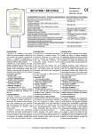
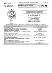
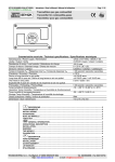
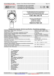
Istruzione / User’s Manual / Manuel d’utilisation
IST-2137.KM01.01 (I-137K99)
SE137KM / SE137KG
Pag.1/4
Rivelatore gas
Gas detector
Détecteur de gaz
Caratteristiche tecniche / Technical specifications / Caractéristiques techniques
ALARM 2
ALARM 1
ON
FAULT
Alimentazione / Power supply / Alimentation
Intervento 1° Allarme
1st Alarm intervention / Seuil 1 d'intervention de alarme
Intervento 2° Allarme
2nd Alarm intervention / Seuil 2 d'intervention de alarme
Uscita / Output / Sortie
Sensore / Sensor / Capteur
Precisione / Accuracy / Precision
Tempo di risposta / Response time / Temps de résponse
Deriva a lungo termine in aria pulita
Long time drift in pure air / Dérive à long terme en air non pullué
Temp./umidità di funzionamento / Operation Temp./Humidity
Température et humidité de fonctionnement
Temp./umidità di immagazzinamento / Storage Temp./Humidity
Température et humidité de stockage
Dimensioni / Size / Dimensions
DESCRIZIONE
L’SE137K è un rivelatore di gas infiammabili con sensore catalitico, costituito da una custodia che contiene il
circuito elettronico e i morsetti di collegamento. Il sensore è inserito nel portasensore posto nella parte inferiore
della custodia. L’SE137K ha 2 relè
d’allarme che intervengono rispettivamente al 10% e al 20% del LIE del gas
di taratura. I relè, di tipo sigillato, sono
normalmente eccitati con contatti in
scambio liberi da tensione. Sul coperchio sono visibili 4 Led che indicano le
condizioni di esercizio:
Led Verde "ON": funzionamento normale.
Led Giallo "SENSOR FAULT":
sensore guasto o scollegato.
Led Rosso "ALARM 1":
relè di allarme (10% LIE).
Led Rosso "ALARM 2":
relè di allarme (20% LEL CH4).
I mod.SE137K vengono utilizzati in sistemi centralizzati di allarme per parcheggi, industrie, ecc.
FUNZIONAMENTO
Il sensore catalitico è poco sensibile
alle variazioni di umidità e temperatura ed è in grado di rilevare molti
gas infiammabili. Per questo anche
se la taratura viene eseguita per uno
specifico gas, può rilevare anche altri gas o solventi infiammabili se
presenti nello stesso locale. Il sensore, quando viene alimentato, necessita di
un tempo di preriscaldo di circa 30 secondi. Dopo questo tempo è in grado di
rilevare il gas, ma raggiunge le condizioni di stabilità ottimali dopo circa 48 ore di
funzionamento
continuo.
TECNOCONTROL S.p.A.
DESCRIPTION
The SE137K is a flammable gas detector employing a catalytic sensor.
The instrument comprises of a plastic enclosure housing the electronic
circuit and the connecting terminals;
the downward facing cylindrical section houses the sensor. This dual
level gas detector has two alarm
thresholds set to 10% and 20% LEL.
The sealed relays are normally activated with tension free changeover
contacts.
On the front panel 4 LEDs shows the
working conditions:
Green LED "ON": normal working condition
Yellow LED "SENSOR FAULT":
faulty or disconnected sensor.
Red LED "ALARM 1":
1st relay activation (10% LEL).
Red LED "ALARM 2":
2nd relay activation (20% LEL).
The SE 137K find their best application
in centralized alarm systems for car
parks, manufacturing industries, etc.
OPERATIONAL DESCRIPTION
Catalytic sensors are almost insensitive to humidity and temperature
variations and are designed to detect various flammable gases. Even
if the calibration is carried out for a
specific gas, they can contemporaneously detect any other flammable
gas that should be present in the
same enviroment.
When powered, the sensor needs a
time of preliminary heating of about
30 seconds, but it attains the optimum stability conditions after about
48 hours continual functioning.
Via Miglioli 97 SEGRATE ( MI )
12÷24Vdc (-10/+15%) / 1,5W
10% LIE / LEL
20% LIE / LEL
relè / relays / relais 24V / 2A SPDT
Catalitico / Catalytic / Catalytique
± 10 %
< 60 secondi / seconds / secondes
< ± 4 %LIE anno
< ± 4 %LEL year / < ± 4 %LIE an
-10 ÷ +50 °C / 5÷90 % r.h. 40°C
-25 ÷ +55°C / 5÷95 % r.h.
187 x 80 x 67 mm / IP65
DESCRIPTION
Le SE137K est un détecteur de gaz inflammables qui utilise un capteur catalytique. L'appareil est constitué d'un boîtier
contenant le circuit électronique et les
borniers de raccordement. Le capteur est
monté dans une tête qui est placé dans
la partie inférieure du boîtier. L'appareil
possède 2 relais d’alarme qui interviennent respectivement à 10% et à
20% LIE. Les relais de type étanche,
sont normalement excités avec
contact inverseurs libres de tension.
Sur la face avant sont visibles 4 Led
qui indiquent les conditions de fonctionnement:
LED verte “ON”: fonctionnement normal
LED jaune “SENSOR FAULT”:
derangement ou capteur déconnecté
LED orange “ALARM 1”:
1er relais d’alarme (10% LIE)
LED rouge “ALARM 2”:
2e relais d’alarme (20% LIE)
Les SE137K sont normalement utilisés
dans les systèmes d’alarmes centralisés
pour parkings, industries, laboratoires etc.
FONCTIONNEMENT
Le capteur catalytique est pratiquement
insensible aux variations de température et d'humidité et il est capable de
détecter plusieurs gaz combustibles.
L'étalonnage est effectué pour le gaz à
détecter mais, dans le même temps, il
peut détécter d’autres gaz combustibles présent dans la pièce. Lorsque le
détecteur est alimenté, le capteur a
besoin d’un temps de préchauffage
d’environ 30 secondes pour être opérationnel, mais les conditions de stabilisation ne seront obtenues qu’après 48
heures
de
fonctionnement.
Tel: 02/26922890 Fax: 02/2133734
Pag.2/4
Istruzione / User’s Manual / Manuel d’utilisation
Guasti: In caso di guasto del sensore si
illumina il Led giallo “FAULT” e interviene il
corrispondente Relè. Questo relè può essere utilizzato per indicare a distanza una
situazione di guasto dei sensori o per segnalare mancanza di alimentazione allo
strumento.
Periodo di funzionamento: L'elem ento
sensibile utilizzato in questo rivelatore
ha una buona stabilità nel tempo. In
condizioni di funzionam ento norm ale in
aria pulita la vita del sensore è circa 10
anni dalla data installazione.
Verifiche Periodiche: Si consiglia di effettuare la verifica di funzionamento ogni 6
mesi e ogni anno procedere alla ritaratura
del circuito con miscela Gas/Aria come
indicato a Pag.4.
Nota importante: tenere presente che in
ambienti particolarmente inquinati o con
vapori di sostanze infiammabili (in particolare solventi), può essere necessario
effettuare più spesso la verifica e/o la
taratura periodica, inoltre la vita utile del
sensore può ridursi notevolmente.
INSTALLAZIONE
I rivelatori vanno installati e posizionati
seguendo tutte le norm e nazionali vigenti per gli impianti elettrici nei luoghi con
pericolo di esplosione e le norm e di sicurezza degli impianti.
Posizionamento L’apparecchio va
installato verticale con il sensore rivolto verso il basso, posizionandolo:
? ? a 20-30cm dal soffitto se il gas da rilevare è più leggero dell'aria
(es.Metano).
? ? a 20-30cm dal pavimento se il gas da
rilevare è più pesante dell'aria
(es.GPL).
Collegamenti elettrici (Fig.1): la
distanza massima cui può essere
installato ogni rivelatore dall'alimentatore è di 800m con cavo da
1,5mm 2 e di 1400m con cavo da
2,5mm 2 a 12 Vcc, mentre è di
7500m con cavo da 1,5mm 2 e di
13000m con cavo da 2,5mm 2 a 24
Vcc. Non serve utilizzare cavi
schermati. Nel caso di alimentazione
di più apparecchi in parallelo, è necessario tener conto della caduta di
tensione sui tratti comuni dei cavi. I
morsetti sono del tipo ad innesto, è
necessario sfilarli per effettuare i
collegamenti. Prestare attenzione
nel reinserirli dato che sono polarizzati.
I relè, di tipo sigillato, sono normalmente eccitati con contatti in scambio liberi da tensione per cui se
manca l’alimentazione si spostano
automaticamente in posizione di allarme.
TECNOCONTROL S.p.A.
Faults: When a sensor fault occurs, the
yellow LED “FAULT” illuminates and the
corresponding relay activates. If necessary, the "FAULT" relay, can be used both
to remotely indicate a damage being occured or to indicate the absence of power
to the instrument.
Average life: The sensitive element used
in this detector has an exellent stability in
time. In fresh air and in normal working
condition the sensor's life is about 10 years
from the date of installation.
Periodical testing: we advise to carry
out working tests every six months.
After 1 year we advise to proceed to
the recalibration of the circuit with
Gas/Air mixture as explained on page
4.
Attention: in polluted environments,
where vapours of flammable agents,
especially solvents, might be present,
the periodical testings and recalibrations should be carried out at shorter
time intervals. In polluted environments the sensor's life can be reduced.
INSTALLATION
The detector must be accurately installed according to the national dispositions in force on the safety of the
plants and installation of electric devices in areas with danger of explosion.
Positioning: The unit must be positioned vertically with the sensor
downwards. The detector should be
installed:
? ?at 20-30 cm below the ceiling if the
gas to be detected is lighter than
air (ex., Methane).
? ?at 20-30 cm from the floor if the
gas to be detected is heavier than
air (ex., LPG).
Electric connections (see Fig.1): the
maximum distance to install each detector from the power supply is 800m
with a 1,5mm 2 cable and 1400m with a
2,5 mm 2 cable at 12 Vdc, whereas is
7500m with a 1,5mm 2 cable and
13000m with a 2,5 cable at 24 Vdc. It
is not necessary to use shielded cables.
If more than one detector is to be
powered in parallel, it is necessary to
consider the voltage drop across the
supply cable. Terminals are plug-in
type: it is necessary to extract them to
make any connections.
Pay attention when you insert them
again, being polarized. The sealed relays are normally activated with tension free changeover contacts, if a
power supply interruption occur, they
automatically deactivate.
Via Miglioli 97 SEGRATE ( MI )
IST-2137.KM01.01
Dérangement: En cas de panne du
capteur la LED jaune “FAULT” s'illumine et le relais de dérangement s'active. Ce relais est aussi destiné à la
signalisation à distance d'un dérangement ou d'une coupure d'alimentation.
Vie moyenne: Le capteur a une
excellente stabilité dans le temps. En
condition de fonctionnement normale
en air non pollué, la vie utile du capteur est d'environ 10 ans à partir de la
date de mise sous tension.
Verification périodique: Il est
conseillé d'effectuer une vérification
de fonctionnement après 6 mois, et
pendant l’année de procéder au réétalonnage du circuit avec une mélange
gaz/air, répertorié en page 4.
Attention: En milieu particulièrement
pollué, avec présence de vapeurs inflammables et en particulier de solvants, il peut être nécessaire d'augmenter la fréquence des temps de vérification et d'étalonnage. En outre, la
vie du capteur peut être réduite.
INSTALLATION
Les détecteurs doivent être installés
selon les normes en vigueur pour les
installations électriques dans les locaux avec danger d'explosion et les
normes de sécurité des installations.
Positionnement: le SE137K doit être
installé en position verticale et le capteur doit être tourné vers le bas. Le détecteur doit être installé:
? ?à une hauteur de 20÷30 centimètres du plafond si le gaz à détecter
est plus léger que l’air (ex. méthane)
? ?à 20÷30 centimètres du plancher
si le gaz à détecter est plus lourd
que l’air (ex. GPL).
Raccordements électriques (Fig.1):
La distance maximale à laquelle
peut être raccordé le SE137K avec
alimentation en12Vcc est de 800m
avec câble 1,5mm 2 et 1400m avec
2
câble 2,5mm . Avec alimentation en
24Vcc de 7500m avec câble 1,5mm 2
et 13000m avec câble 2,5mm 2
Si l’on a l’alimentation de plusieurs
appareils en parallèle, il faudra
considérer la chute de tension sur
les cables.
Les borniers sont de type débrochables polarisés et pour effectuer les
connexions il faut les débrocher.
Les relais sont normalement excités
avec contact inverseurs libres de
tension.
Tel: 02/26922890 Fax: 02/2133734
IST-2137.KM01.01
Istruzione / User’s Manual / Manuel d’utilisation
Il relè “ALARM 2” è ritardato di circa 40
secondi. Il ritardo può essere eliminato,
sfilando il ponticello “JP1” sul circuito
stampato come indicato in figura 3.
AVVERTENZE
Attenzione: Alcune sostanze causano una
diminuzione permanente di sensibilità. Evitare che il sensore venga a contatto con
vapori di Silicone, Tetraetile di Piombo o
Esteri fosfati. Altre sostanze causano una
temporanea perdita di sensibilità. Questi
“inibitori” sono gli Alogeni, l’Idrogeno solforato, il Cloro, gli Idrocarburi clorurati (Trielina o Tetracloruro di carbonio). Dopo un
breve tempo in aria pulita, il sensore riprende il proprio funzionamento normale.
Importante: Il sensore catalitico funziona solo in presenza di Ossigeno.
Non usare gas puri o l'accendino direttamente sul sensore che potrebbe venire irrimediabilmente danneggiato.
Note sui vari modelli
SE137KG (GPL)
L’SE137KG è in grado di rivelare GPL.
Il GPL è un gas più pesante dell'aria,
formato da una miscela composta dal
20÷30% di Propano (C3H8) e dall'80÷70% di Butano (C4H10). La densità
relativa all'aria è 1,56 per il Propano e
2 per il Butano; il LIE (Limite Inferiore
di Esplosività) è 2% v/v per il Propano
e 1,5% v/v per il Butano. Le tarature
per GPL sono normalmente effettuate
con gas Butano.
SE137KM (Metano CH4)
L’SE137KM è in grado di rivelare Metano. Il Metano è un gas combustibile
più leggero dell'aria. La sua densità
relativa all'aria è 0,55 ed il suo LIE è
5%v/v (%Volume).
TARATURA
La verifica e/o taratura del SE137K
può essere eseguita con il tester di calibrazione Tecnocontrol (mod. TC011).
Importante: è possibile utilizzare sia
le bombole monouso da un litro che
quelle ad alta pressione con riduttore
con miscela Gas al 10%LIE (ALARM
1) e al 20%LIE (ALARM 2) in aria
20,9% Ossigeno, in quanto i sensori
catalitici non possono funzionare in
assenza di ossigeno.
Nota: La taratura è effettuata con gas
calibrato. La verifica periodica e/o la
taratura in campo deve essere effettuata solo da personale addestrato e
autorizzato. In alternativa, si consiglia
di effettuare solo la verifica senza toccare i trimmer e nel caso i valori non
siano quelli richiesti contattare il nostro
laboratorio.
TECNOCONTROL S.p.A.
The second relay intervention is retared by almost 40 seconds. To remove the delay, remove the jumper
“JP1” on the PCB as shown in the figure 3.
WARNING
Warning: Some substances cause a
permanent reduction in sensitivity.
Avoid contacts of the sensor with
vapours of Silicone compunds,
Tetra-ethyl Lead and Phosphate esters
Some other substances produce a
temporary loss of sensitivity. These
“inhibitors” include Hidrogen sulfide,
Chlorine, Chlorinated hydrocarbons
and halohenated compounds. The
sensitivity is recovered after a short
period of running in clear air.
Important: The catalytic sensor operate only in presence of Oxygen.
Do not use pure gases or a lighter
directly on the sensor since they
could damage it irremediabily.
Notes on the available Models
SE137KG (LPG)
Model SE137KG is calibrated to detect LPG. This gas is heavier than
air and consists of a mixture of 2030% Propane (C3H 8) and 80-70%
Butane (C4H 10). Propane density as
to air is 1.56 while Butane' is 2. The
LEL (Lower Explosivity Limit) is
2%v/v for Propane and 1,5%v/v for
Butane. Standard calibration to LPG
is carried out with Butane gas.
SE137KM (Methane CH4)
Model SE137KM is calibrated to
Methane. Methane is a gas lighter than
air, its density as to air is 0.55, and its
LEL 5%v/v (%volume).
CALIBRATION
The SE137K calibration and /or verification should be carried out by using the Tecnocontrol calibration kit
(Model TC011).
Very Important note: Both high
pressure sample gas bottles with reducer and 1 litre gas bottles may be
employed. Use sample bottles with a
gas mixture of 10% LEL (Alarm 1)
and 20% LEL (Alarm 2) in Air 20.9%
Oxygen, as catalytic sensors don’t
work without Oxygen.
Note: Calibration is carried out with
sample gas. The calibration rutine is
to be carried out by trained or
authorised personnell only. As an
alternative it is advised to check the
calibration without operating on the
trimmers, and in case the values are
not the required ones please apply
to our Laboratory.
Via Miglioli 97 SEGRATE ( MI )
Pag.3/4
L’intervention du 2e relais “ALARM 2”
est retardée d’environ 40 secondes.
Ce rétard peut être eliminé en enlévant le cavalier “JP1” sur le circuit imprimé, comme indiqué dans la figure
3.
AVERTISSEMENT
Attention: Eviter que le capteur
vienne au contact de vapeurs de silicone, plomb tétraéthyle ou hydrocarbures chlorés, ces substances pouvant
en réduire irréversiblement la sensibilité. Le contact occasionnel avec des
solvants type trichloréthylène ou tétrachlorure de carbone peuvent inhiber
temporairement le capteur. Après un
bref temps en air pur le capteur reprend son fonctionnement normal.
Attention: Les capteurs catalytiques
fonctionnent seulement en présence
d’Oxygène. Eviter l'usage de gaz pur
ou du briquet sur le capteur, qui pourrait être irrémédiablement endommagé.
Les modèles
SE137KG (GPL)
Le SE137KG permet de détecter le
GPL. Le GPL est un gaz plus lourd
que l'air, formé d'un mélange composé
de 20-30% de Propane (C3H8) et de
70-80% de Butane (C4H10). La densité
relative à l'air est 1,56 pour le Propane
et 2 pour le Butane. La LIE (limite inférieure d'explosivité) du Propane est
2% v/v et celle-ci du Butane est 1,5%
v/v. Tous les étalonnages pour GPL
sont fait avec du Butane.
SE137KM (Methane CH4)
Le SE 137K perm et de détecter le Méthane. Le Méthane est un gaz plus léger
que l'air. Sa densité par rapport à l'air
est 0,55, sa LIE est 5%v/v (% volum e).
ETALONNAGE
Il est possible de vérifier et étalonner le
SE137K avec le Kit d’etalonnage Tecnocontrol. (Mod. TC011).
Attention: il est possible d’utiliser soit la
bouteille de 1 litre, soit une bouteille à
haute pression avec réducteur, avec
m élange Gaz 10%LIE et 20%LIE en air
(O2= 20,9%). Les capteurs catalytiques
ne fonctionnent pas en absence
d’oxygène.
Attention: L'étalonnage est effectué
avec du gaz étalon. L'étalonnage
doit être effectué seulement par le
personel autorisé. Dans le cas
contraire il est conseillé de vérifier le
calibrage sans toucher les potentiomètres et dans le cas où les valeurs
ne sont pas correctes, veuillez prendre contact avec notre Laboratoire.
Tel: 02/26922890 Fax: 02/2133734
Pag.4/4
Istruzione / User’s Manual / Manuel d’utilisation
Per la regolazione del trimmer è necessario utilizzare un cacciavite a taglio di
dimensione adeguata
Aprire il coperchio della custodia.
“Regolazione dell’ALLARME 1”.
Per verificare e/o tarare lo strumento va utilizzata la bombola con la
stessa miscela Gas/aria al 10% LIE
per cui è stato tarato il rivelatore.
Collegare la bombola al Flussimetro
(Fig.4); far affluire il gas a circa
0,15÷0,3 l/min, attendere circa 3
minuti e verificare che si illumini il
Led Rosso “ALARM 1”. Se così non
fosse ruotare lentamente il Trimmer
“P1” (Fig.3) fino all’accensione del
Led “ALARM 1”.
“Regolazione dell’ALLARME 2”con la
stessa miscela Gas/aria al 20%LIE per
cui è stato tarato il rivelatore, collegare la
bombola al Flussimetro (Fig.4), far affluire il gas a circa 0,15÷0,3 l/min, attendere
circa 3 minuti e verificare che si illumini il
Led Rosso “ALARM2”. Se così non fosse ruotare lentamente il Trimmer “P2”
(Fig.3) fino all’accensione del Led
“ALARM 2”.
C
NA
NC
C
Pour le réglage du potentiomètre il est
nécessaire d’utiliser un tournevis de dimension adaptée.
Ouvrir le couvercle du boîtier.
“Réglage d’ALARM 1”. Pour l'étalonnage utiliser une bouteille avec le mélange spécifique gaz 10%LIE/air utilisé
pour la calibration de l’appareil. Raccorder la bouteille au débimètre (Fig
4) faire débiter le gaz à environ 0,150,3 l/min, attendre 3 minutes et vérifier que la LED rouge “ALARM 1”
s’illumine. Si nécéssaire, régler le potentiomètre “P1” jusqu’à l’allumage de
la LED (Fig.3).
“Réglage d’ALARM 2”: pour l'étalonnage utiliser une bouteille avec le mélange spécifique gaz 20%LIE/air utilisé
pour la calibration de l’appareil. Raccorder la bouteille au debimètre (Fig
4) faire débiter le gaz à environ 0,150,3 l/min, attendre 3 minutes puis vèrifier que la LED rouge “ALARM 2”
s’illumine. Si nécéssaire, régler le potentiomètre “P2” jusqu’à l’allumage de
la LED (Fig.3).
AL2
AL1
NA
NC
C
FAULT
NC
NA
12÷24Vdc
Employ a right sized single slot screwdriver to operate on the trimmer.
Remove the sensor's cover.
“ALARM 1 calibration”. To verify
or/and calibrate the instrument use a
sample bottle with the same 10%LEL
specific gas/air mixture which had been
used to calibrate the unit. Connect the
sample gas bottle (Fig.4) to the flowmeter, set the flowmeter on a 0,15÷0,3
l/min flow rate, wait for 3 minutes and
verify the red LED “ALARM 1” illuminates. If necessary slowly turn the “P1”
potentiometer as long as the red LED
“ALARM 1”illuminates (See fig.3).
“ALARM 2 calibration”. Use a sample
bottle with the same 20%LEL specific
gas/air mixture which had been used to
calibrate the unit. Connect the sample
gas bottle (Fig.4) to the flowmeter, set
the flowmeter on a 0,15÷0,3 l/min flow
rate, wait for 3 minutes and verify the
red LED “ALARM 2” illuminates. If necessary slowly turn the “P2” potentiometer as long as the red LED “ALARM 2”
illuminates (See fig.3).
IST-2137.KM01.01
+
Fig. 1 Schema di collegamento
Wiring diagram
L
4 / Schéma
Fig. 2 Dimensioni
Outline Dimensions / Dimensions
230V-50Hz
JUMPER / CAVALIER
0,3L/min
JP1
P2 “ALARM 2”
P1 “ALARM 1”
Fig.3 Verifica / Test / Vérification
TECNOCONTROL S.p.A.
Via Miglioli 97 SEGRATE ( MI )
Fig.4 Tester di calibrazione
Calibration Tester
Kit de Calibration
Tel: 02/26922890 Fax: 02/2133734