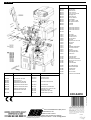
1
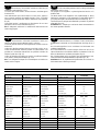
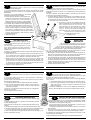
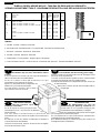
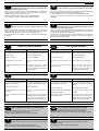
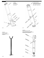
ISTRUZIONI PER L'USO E L’INSTALLAZIONE
INSTRUCTIONS POUR L'UTILISATION ET L’INSTALLATION
OPERATING AND INSTALLATION INSTRUCTIONS
GEBRAUCHSANWEISUNGEN UND INSTALLATION
Barriera irreversibile per controllo traffico veicolare - Barrière irréversible pour le contrôle du trafic véhiculaire
Irreversible barrier for vehicular traffic control - Selbsthemmende Schranke zur Verkehrssteuerung
Mod.
ECO-RAPID
3000
Fig.1
I
1000
1065
300x300
Misure in mm - Mesures en mm - Measurements in mm - Abmessungen in mm
IMPORTANTI ISTRUZIONI PER LA SICUREZZA
ATTENZIONE - É IMPORTANTE PER LA SICUREZZA DELLE PERSONE
CHE VENGANO SEGUITE TUTTE LE ISTRUZIONI
CONSERVARE CON CURA QUESTE ISTRUZIONI
1° - Tenete i comandi dell'automatismo (pulsantiera, telecomando etc.) fuori dalla portata dei
bambini. I comandi devono essere posti ad un’altezza minima di 1,5mt dal suolo e fuori dal
raggio d’azione delle parti mobili.
2° - Effettuare le operazioni di comando da punti ove l'automazione sia visibile.
3° - Utilizzare i telecomandi solo in vista dell'automazione.
4° - Prima di eseguire qualsiasi operazione di installazione, regolazione, manutenzione
dell’impianto, togliere la tensione agendo sull’apposito interruttore magnetotermico collegato
a monte dello stesso.
5° - Avvertenze: Sulle altre misure di Protezione contro rischi attinenti l'installazione o
l'utilizzazione del Prodotto vedi, a completamento di questo libretto di Istruzioni, le
Avvertenze RIB allegate.
Qualora queste non siano pervenute chiederne l'immediato invio all'Ufficio Commerciale RIB.
LA DITTA RIB NON ACCETTA NESSUNA RESPONSABILITÀ per eventuali danni provocati
dalla mancata osservanza nell'installazione delle norme di sicurezza e le leggi attualmente in
vigore.
F
INSTRUCTIONS IMPORTANTES POUR LA SECURITE
IL EST IMPORTANT POUR LA SECURITE DES PERSONNES
DE SUIVRE ATTENTIVEMENT TOUTES INSTRUCTIONS
GARDER MODE D’EMPLOI
1° - Gardez les commandes de l'automatisme (boutons poussoirs, télécommande etc.) hors
de la portée des enfants. Les commandes doivent être placées au minimum à 1,5 m du
sol, et hors de rayon d’action des pièces mobiles.
2° - Il faut donner les commandes d'un lieu, où on peut voir la porte.
3° - Il faut utiliser les émetteurs seulement si on voit la porte.
4° - Avant d’exécuter quelconques opérationd’installation, réglage, entrietien de l’installation,
couper la tension avec l’interrupteur magnétothermique approprié connecté en amont.
5° - Avertissements: Sur les autres mesures de Protection contre les risques relatifs a
l'installation ou l'utilisation du Produit, voir, à titre de complément de ce livret
d'instructions, les Avertissements RIB ci-jointes. Dans le cas où celles-ci ne vous
seraient pas parvenues, en demander l'envoi immédiat au Bureau d’Exportation de RIB.
L'ENTREPRISE R.I.B. N'ACCEPTE AUCUNE RESPONSABILITÉ pour des dommages
éventuels provoqués par le manque d'observation lors de l'installation des normes de
sécurité et lois actuellement en vigueur.
GB
IMPORTANT SAFETY INSTRUCTIONS
WARNING - IT IS IMPORTANT FOR THE
SAFETY OF PERSONS TO FOLLOW ALL INSTRUCTIONS
SAVE THESE INSTRUCTIONS
1° - Keep the automatic control (push-button, remote control, etc) out of the reach of
children. The control systems must be installed at a minimum hight of 1.5m from
the ground surface and not interfere with the mobile parts.
2° - Command pulses must be given from sites, where you can see the gate.
3° - Use transmitters only if you can see the gate.
4° - Before starting nay installation and operation or maintenance work make sure to
cut off power supply by turning the general magnetothermic switch off.
5° - Warnings: when you have finished reading this instruction booklet, please refer to
the RIB instructions attached for the other precautionary measures against risks
connected with the installation or use of the product. If you have not received
these, ask RIB Export Office to send them immediately.
R.I.B. IS NOT LIABLE for any damage caused by not following the safety regulations
and laws at present in force not being observed during installation.
D
WICHTIGE ANWEISUNGEN FÜR DIE SICHERHEIT
ACHTUNG - UM DIE SICHERHEIT VON PERSONEN VOLLKOMMEN
GARANTIEREN ZU KöNNEN, IST ES WICHTIG, DASS ALLE
INSTALLATIONSVORSCHRIFTEN BEACHTET WERDEN
1° - Bewahren Sie die Geräte für die automatische Bedienung (Drucktaster, Funksender,
u.s.w.) an einem für Kinder unzugänglichen Platz auf. Die Steuerungen müssen auf
einer Mindesthöhe von 1,5 m angebracht werden und sich ausserhalb der Raumes
der bewegenden Teile befinden.
2° - Die automatische Steuerung darf nur bedient werden, wenn das Tor sichtbar ist.
3° - Die Funksender nur benützen, wenn das Tor sichtbar ist.
4° - Before starting nay installation and operation or maintenance work make sure to cut
off power supply by turning the general magnetothermic switch off.
5° - Achtung: Für weitere Schutzmaßnahmen im Rahmen der Installation und Anwendung
der Produkte siehe die beiliegenden RlB-Sicherheitshinweise, die diese
Gebrauchsanleitung ergänzen. Sollten Sie diese nicht erhalten haben, fordern Sie sie
bitte sofort bei der RlB Exportabteilung an.
R.I.B. HAFTET NICHT für eventuelle Schäden, die bei der Installation durch
Nichtbeachtung der jeweils gültigen Sicherheitsvorschriften entstehen.
Pag. 2 di 12
I
IMPORTANTI ISTRUZIONI DI SICUREZZA
PER L’INSTALLAZIONE
ATTENZIONE - UNA SCORRETTA INSTALLAZIONE PUÓ PORTARE A DANNI RILEVANTI
SEGUIRE TUTTE LE ISTRUZIONI PER UNA CORRETTA INSTALLAZIONE
1° - Questo libretto d'istruzioni è rivolto esclusivamente a del personale specializzato che sia a
conoscenza dei criteri costruttivi e dei dispositivi di protezione contro gli infortuni per i cancelli, le
porte e i portoni motorizzati (attenersi alle norme e alle leggi vigenti).
2° - Se non é previsto nella centralina elettrica, installare a monte della medesima un'interruttore di tipo
magnetotermico (onnipolare con apertura minima dei contatti pari a 3mm) che riporti un marchio di
conformità alle normative internazionali.
3° - Per la sezione ed il tipo dei cavi la RIB consiglia di utilizzare un cavo di tipo NPI07VVF con sezione
minima di 1,5mm2 e comunque di attenersi alla norma IEC 364 e alle norme di installazione vigenti
nel proprio Paese.
F
IMPORTANT SAFETY INSTRUCTION
FOR INSTALLATION
GB
WARNING -INCORRECT INSTALLATION CAN LEAD TO SEVERE INJURY
FOLLOW ALL INSTALLATION INSTRUCTIONS
1° - This instruction booklet is exclusively dedicated to specialized staff who are aware of the
construction criteria and of the accident prevention protection devices for motorized gates and
doors (according to the current regulations and laws).
2° - To maintain electrical parts safely it is advisable to equip the installation with a differential thermal
magnetic switch (onnipolar with a minimum opening of the contacts of 3mm) and must comply
with the international rules.
3° - As for electric cable type and section RIB suggests cable type <HAR> with minimum section of
1,5mm2 and however respect IEC 364 rule and general national security regulations.
IMPORTANT MODE D’EMPLOI DE SECURITE
POUR L’INSTALLATION
WICHTIGE SICHERHEITSVORSCHRIFTEN
FÜR DIE INSTALLATION
D
ACHTUNG - EINE FALSCHE INSTALLATION KANN ZU BEDEUTENDE SHADEN FÜHREN.
FÜR EINE KORREKTE ANLAGE ALLE GEBRAUCHSANWEISUNGEN FOLGEN
1° - Diese Montageanweisung kann ausschließlich von der Fachleuten gebraucht werden, die
die Instandsetzung und die Schutzvorrichtungen zur Verhinderung von Unfällen bei motorisierten
Toren kennen (nach die aktuellen Normen und Gesetze).
2° - Für die Wartung der elektrischen Teile ist es ratsam, zwischen der Anlage und dem
Netzanschluß einen magnetisch-thermischen Differenzialschalter (mit der minimale Öffnung allen
Kontakte von 3 mm) unterbricht die ein Konformitätzeichen aller internationaler Normen vorträgt.
3° - Für den Kabelguerschnitt und die Kabeltypen halten Sie sich an den Normen IEC 364 (minimale
Kabelquerschnitt von der 1,5 mm2 mit der Bezeichnung <HAR>) und für die Montage an die
Normen des jeweiligen Landes.
ATTENTION - UNE INSTALLATION INCORRECTE PEUT CAUSER DE GRANDS DOMMAGES
SUIVRE TOUTES INSTRUCTIONS POUR UNE CORRECTE INSTALLATION
1° - Ce manuel d'instruction est adresse seulement au personnel specialisé qui a une
connaissance des critères de construction et des dispositifs de protection contre les accidents en ce
qui concerne les portails, les portes et les portes cochères motorisees (suivre les normes et les lois
en vigueur).
2° - A fin de proceder al'entretien des parties electriques, connecter à l'installation un distonteur
differentiel magneto thermique (qui disconnait toutes les branchements de la ligne avec ouverture
min. des branchements de 3 mm ) et qui soit conforme aux normes internationales.
3° - Pour la section et le type des câbles à installer nous vons conseillons di utiliser un cable <HAR>
avec une section min de 1,5 mm 2 en respectant quand même la norme IEC 364 et les normes
nationales d'installation.
➀
➃
➁
➁
➂
➂
➁
➁
➂
➂
➁
➁
➂
➂
➄
Fig.2
➀ Barriera ECO-RAPID
➁ Fotocellule di sicurezza
➂ Colonnina porta fotocellula zincata
➃ Costa a fotocellula o pneumatica
➄ Sensore magnetico
- Selettore a chiave
- Antenna radio
➀ Barrière ECO-RAPID
➁ Photocellules p/protection
➂ Poteau zingué p/cellule
➃ Cordon de sécurité avec Photocellule
➄ Boucle magnetique
- Selecteur
- Antenne radio
➀ ECO-RAPID barrier
➁ Photoelectric cells
➂ Galvanized column for P.E. cells
➃ Strip with Photo electric cells
➄ Magnetic loop
- Key selector
- Tuned aerial
➀ ECO-RAPID Schranke
➁ Photozellen
➂ Verzinkte Metallsäule als Photozellenträger
➃ Photozellen Sicherheitskontaktleiste
➄ Magnetschleife
- Schlüsselschalter
- Antenne
Pag. 3 di 12
CARATTERISTICHE TECNICHE ECO-RAPID
Motoriduttore irreversibile ambidestro utilizzato per
movimentare aste lunghe fino a 3 mt.
La colonna può essere fornita in versione zincata e verniciata oppure
in versione inox.
L'asta della barriera può essere fornita in un unico pezzo, oppure in
caso di ostacoli superiori riscontrabili durante la corsa, è possibile
richiederla snodata specificando l'altezza dell'ostacolo dal pavimento
(Fig.12).
L'asta della barriera è predisposta per l'inserimento di una costa
pneumatica o di una costa a fotocellula (Fig.1-13).
N.B. È obbligatorio uniformare le caratteristiche della barriera alle
norme e leggi vigenti.
ECO-RAPID TECHNICAL CHARACTERISTICS
Lh./rh.irreversible gearmotor used for raising and lowering
barrier poles up to 3 m. long.
The upright can be supplied in a painted galvanized version or in
stainless steel.
The barrier boom can be supplied as one unjointed length or, where
headroom is restricted, it can be requested in an articulated version if
you specify the height of the obstruction above road level (Fig. 12).
The barrier boom is designed to be fitted with a pneumatic or photocell
safety strip (Fig. 1-13).
ATTENTION: It is compulsory to conform the barrier characteristics to
the current regulations and laws.
CARACTERISTIQUES TECHNIQUES ECO-RAPID
Motoréducteur irréversible "ambidextre” utilisé pour
actionner des lisses pouvant atteindre jusqu'à 3 m de long.
La colonne peut être fournie en version galvanisée et vernie ou bien en
version inox.
La lisse de la barrière peut être fournie en un seul bloc ou bien, au cas
où elle rencontrerait des obstacles pendant son actionnement, il est
possible de la commander désarticulée en spécifiant la hauteur de
l'obstacle à partir du sol (fig. 12).
La lisse de la barrière est prête pour recevoir un profilé pneumatique
ou un profilé à cellule photo-électrique (fig. 1-13).
N.B.: Il est obligatoire d’adapter les caracteristiques du barrière aux
normes et lois en vigueur.
TECHNISCHE DATEN GETRIEBEMOTOR
Selbsthemmender, auf beiden Seiten montierbarer
Getriebemotor zum Antrieb von Schrankenbäumen mit Länge bis zu 3
m.
Das Schrankengehäuse ist aus verzinktem und lackiertem oder
rostfreiem Stahl lieferbar.
Der Schrankenbaum ist in einem einzigen Stück bzw. im Fall von
oberen Hindernissen als Knickbaum lieferbar. Im letzteren Fall ist die
Höhe des Hindernisses vom Boden anzugeben (Fig. 12).
Der Schrankenbaum ist für den Einbau einer pneumatischen- bzw.
einer Fotozellensicherheitskontaktleiste vorgerüstet (Fig. 1-13).
ACHTUNG: Mann ist verpflichtet die Eigenschaften des Schranke zu
die Gesetznormen in Einklang zu bringen.
I
F
GB
D
CARATTERISTICHE
TECNICHE
CARACTERISTIQUES
TECHNIQUES
TECHNICAL
DATA
TECHNISCHE
EIGENSCHAFTEN
Lunghezza max.asta
Longueur maxi de la lisse
Max. boom lenght
Max. Baumlänge
m.
3
2,5
140
ECO-RAPID
Opening time
Öffnungszeit
s
Coppia max sull'albero porta asta Couple maxi arbre sortie
Max. torque
Max. Drehmoment
Nm
Alimentazione e frequenza CEE Alimentation et frequence CEE
EEC Power supply
Stromspannung und frequenz CEE
Potenza motore
Puissance moteur
Motor capacity
Motorleistung
W
150
Assorbimento
Absorption
Power absorbed
Stromaufnahme
A
0,7
Condensatore
Condensateur
Capacitor
Kondensator
µF
8
n° di cicli
Nbre de cycles
No. cycles
Anzahl der Zyklen
n°
Alimentazione e frequenza
Alimentation et frequence
Power supply
Stromspannung und frequenz
Potenza motore
Puissance moteur
Motor capacity
Motorleistung
W
150
Assorbimento
Absorption
Power absorbed
Stromaufnahme
A
0,7
Condensatore
Condensateur
Capacitor
Kondensator
µF
8
n° di cicli
Nbre de cycles
No. cycles
Anzahl der Zyklen
n°
6500 - 2,5s/2s
Alimentazione e frequenza
Alimentation et frequence
Power supply
Stromspannung und frequenz
Potenza motore
Puissance moteur
Motor capacity
Motorleistung
W
160
Assorbimento
Absorption
Power absorbed
Stromaufnahme
A
1,5
Condensatore
Condensateur
Capacitor
Kondensator
µF
25
n° di cicli
Nbre de cycles
No. cycles
Anzahl der Zyklen
n°
6500 - 2,5s/2s
Tipo di olio
Type d'huile
Lubrification
Ölsorte
Peso max
Poids maximun
Weight of electroreducer
Motorgewicht
Kg
Rumorosità
Bruit
Noise
Geräusch
db
<70
Volume
Volume
Volume
Volumen
m3
0,103
Grado di protezione
Indìce de protection IP
Protection IP
Schutzart IP
IP
557
Tempo di apertura
Temps d'ouverture
230V~ 50Hz
6500 - 2,5s/2s
220V~ 60Hz
110V~ 60Hz
IP MELLANA 100
62
Pag. 4 di 12
I
MONTAGGIO DELLA ECO-RAPID
Dopo aver cementato il basamento di fissaggio nella posizione da Voi
ritenuta ideale, procedete nel fissaggio della ECO-RAPID utilizzando i dadi in dotazione
e una chiave esagonale n°19.
Di seguito eseguite il montaggio dell'asta che deve essere effettuato in tre fasi.
1°-A terra si devono assemblare i seguenti particolari: l'asta, l'anima per il
tubolare e il mozzo porta asta, utilizzando la vite a testa svasata in
dotazione e una chiave a brugola n°8 (per meglio comprendere le
voci citate osservare la Fig.3-8-9).
2°-La barriera viene fornita con la molla di bilanciamento
rilasciata, quindi l'asta con il suo mozzo deve essere inserita
in posizione verticale nell'albero porta asta.
3°-Il fissaggio finale dell'asta si esegue tramite la vite a testa
cilindrica con esagono incassato in dotazione utilizzando la
chiave "RIB", dopo di che si applicano i tappi .
L'elettroriduttore è di tipo irreversibile e non necessita di alcun tipo di
bloccaggio esterno per mantenere un'efficace posizione di chiusura.
F
MONTAGE DE LA ECO-RAPID
Après avoir cimenté l'embase de fixation dans la
position que vous jugerez idéale, passer à la fixation de la ECO-RAPID
en utilisant les écrous fournis et une clef hexagonale n°19.
Passer ensuite au montage de la lisse qui s'effectue en trois
phases:
1° - Assembler au sol les éléments suivants: la lisse, l'âme pour le
tubulaire et le moyeu porte-lisse, en utilisant la vis à tête fraisée
fournie et une clef hexagonale n°8 (Fig.3-8-9).
2° - La barrière est fournie avec le ressort d'équilibrage détendu; il faut donc
introduire la lisse avec son moyeu dans l'arbre porte-lisse en position
verticale.
3° - Effectuer la fixation finale de la lisse à l'aide de la vis à tête cylindrique avec
l'hexagone emboîté fourni, en utilisant la clef “RIB” puis appliquer les bouchons.
L'électroréducteur est de type irréversible et n'a besoin d'aucun type de blocage
extérieur pour maintenir une position correcte de fermeture.
I
SICUREZZE ELETTRICHE
F
SECURITES ELECTRIQUES
Nella ECO-RAPID i finecorsa, il motore, e il lampeggiatore sono già
collegati al quadro elettronico di comando.
Sono da collegare solamente i fili di una pulsantiera, delle fotocellule e, naturalmente,
della tensione di alimentazione.
Le persone e le cose devono essere protette da eventuali schiacciamenti dovuti a un
comando involontario perciò è obbligatorio installare almeno una coppia di fotocellule o
un sensore (pneumatico o a fotocellula) da collocarsi sotto l'asta come in Fig.1-2-13 .
Per i collegamenti ed i dati tecnici degli accessori attenersi ai relativi libretti.
Dans la ECO-RAPID, les fins de course, le moteur et la lampe
clignotante sont déjà branchés au coffret électronique de commande.
Relier uniquement les fils au coffret de commande, des cellules photo-électriques et,
bien entendu, de la tension d'alimentation.
Personnes et objets doivent être protégés contre les écrasements éventuels dus à une
commande involontaire; il est donc obligatoire d'installer au moins un jeu de cellules
photo-électriques ou bien un capteur (pneumatique ou à cellule photoélectrique) sous la
lisse (Fig. 1-2-13).
Pour ce qui est des raccordements et des données techniques des accessoires, se
référer à leur manuel.
GB
ASSEMBLING THE “ECO-RAPID”
D
MONTAGE ECO-RAPID
GB
ELECTRICAL SAFETY DEVICES
D
ELEKTRISCHE SICHERHEITEN
After you have cemented in the base plate where you want it, mount
ECO-RAPID using the nuts provided and a no. 19 hexagonal wrench.
Then assemble the barrier arm in three phases as follows:1.- Mount the barrier arm fixing attachments to the boom arm using the countersunk
screw supplied and a no. 8 Allen key (see Fig.3-8-9).
2.- The barrier is supplied with the balancing spring decompressed so the barrier arm
and its attachment must be inserted, in vertical position, into the barrier arm
fixing attachment.
3.- Finally, the barrier arm is fixed in position with the socket screw provided, using the
“RIB” key, after which fit the screw-caps.
The gear unit is irreversible so no kind of external locking device is necessary to keep the
barrier in securely closed position.
Nach Zementeinbettung des Sockels in einer günstigen Position, die
Schranke ECO-RAPID mit den beigepackten Schrauben und einem Inbusschlüßel SW 19
montieren.
Darauf hin die Montage des Schrankenbäumes in drei Phasen vornehmen.
1.- Am Boden sind folgende Bauteile zusammenzubauen: Der Schrankenbaum,
innere un äußere Armhalterung des Schrankenbäumes die mit bereits
beigepackten Inbusschrauben n°8 und mit passendem Schlußel auf
den Schrankenbaum montiert werden (Fig.3-8-9).
2.- Die Schranke wird mit entspannter Ausgleichsfeder
geliefert, daher ist die Armhalterung vertikal auf die
Fig.3
Antriebswelle einzusetzen.
3.- Abschließend den Schrankenbaum mit passendem Inbussschrauben auf die
Antriebswelle mit RIB-Inbusschließel befestigen und die Stöpsel aufsetzen.
Der Getriebemotor ist selbsthemmend, daher wird automatisch ohne Einsatz einer äußeren
Sperrvorrichtung eine wirksame Schließstellung eingehalten.
The ECO-RAPID limit switches, motor and flasher unit are already
connected up to the electronic control panel.
Only the wiring of a push-button panel, the photocells and, naturally, the supply voltage
have to be connected up.
People and objects must be protected from crushing as a result of an inadvertent
command, so at least a pair of photoelectric cells or a sensor (pneumatic or
photocellular) positioned below the barrier boom is obligatory (Fig.1-2-13).
For connections and technical data of accessories refer to the appropriate booklets.
Bei der ECO-RAPID sind die Endschalter, der Motor und die
Blinkleuchte werkseitig an die elektronische Steuertafel angeschlossen.
Es sind nur mehr die Kabel der Druckknopftafel, der Fotozellen und der
Versorgungsspannung anzuschließen.
Zum Quetschschutz von Personen und Sachen durch einen unbeabsichtigten Befehl ist
mindestens ein Fotozellenpaar bzw. ein Sensor (pneumatisch oder Fotozelle) unter der
Stange zu installieren (Fig. 1-2-13).
Für die Anschlüsse und technische Daten der Zubehörteilen verweisen wir auf die
entsprechenden Bedienungshandbücher.
Pag. 5 di 12
I
REGOLAZIONE FINECORSA
Normalmente la barriera Vi viene fornita con i finecorsa già regolati per
permettere il movimento ideale dell'asta.
In caso di errato livellamento della piastra da cementare, l'asta potrebbe non risultare
perfettamente orizzontale o verticale con un conseguente cattivo risultato estetico
dell'installazione.
Per ovviare a ciò è possibile modificare la corsa dell'asta
intervenendo sui finecorsa meccanici ed elettrici:
1°-A barriera sbloccata, utilizzate una chiave esagonale n°19
per sbloccare i dadi di fermo (A) e una chiave a brugola n°8
per svitare o riavvitare le viti a testa svasata (B) di
regolazione dei finecorsa meccanici in modo da delimitare
immediatamente il nuovo arco descritto dall'asta della barriera.
2°-Così facendo i finecorsa elettrici sono ora da regolare in modo
tale da delimitare il movimento elettrico del motore per la nuova
corsa che l'asta deve descrivere. Per far ciò è necessario
utilizzare una chiave a brugola n°3 con la quale vengono rilasciate
le due camme (C) di registro finecorsa. Una volta che l'asta è
posizionata in base alla battuta di fermo meccanico è sufficiente
ruotare la camme interessata in modo tale da far scattare il
microinterruttore di finecorsa
3° - Ribloccare le camme.
REGLAGE FINS DE COURSE
F
Normalement, la barrière est fournie avec les fins de course déjà réglés
de façon à imprimer à la lisse le mouvement idéal.
En cas de nivellement erroné de la plaque à cimenter, la lisse pourrait ne pas arriver
parfaitement horizontale ou verticale, ce qui compromettrait le résultat esthétique de
l'installation.
Pour éviter ce problème, il est possible de modifier la course de la lisse en intervenant
sur les fins de course mécaniques et électriques.
1° - Sur barrière débloquée, utiliser une clef hexagonale n°19 pour débloquer les écrous
d'arrêt (A) et une clef hexagonale n°8 pour dévisser ou revisser les vis à tête fraisée
(B) de réglage des fins de course mécaniques de façon à délimiter immédiatement
le nouvel arc que suivra la lisse de la barrière.
2° - De cette façon, les fins de course électriques doivent être
réglés afin de délimiter le mouvement électrique du moteur
A
C
pour la nouvelle course de la lisse. Pour cela, il est
nécessaire d'utiliser une clef hexagonale n°3 à l'aide de
laquelle on desserre les deux cames de réglage fin de
course (C). Lorsque la lisse est placée par rapport àla
butée d'arrêt mécanique, il suffit de faire tourner la came
intéressée de façon à faire déclencher le
microinterrupteur de fin de course.
3° - La rebloquer à la fin.
B
GB
LIMIT SWITCH SETTING
Normally the barrier is supplied to you with
the limit switches already set to allow optimum
barrier movement.
If the base plate has not been cemented in on a level
plane, the boom might be not perfectly horizontal or
Fig.4
vertical, with the result that the aesthetic appearance of the
installation is poor.
To avoid this, it is possible to alter the trajectory of the boom by adjusting the mechanical
and electrical limit switches.
1. - With the barrier up, use a no. 19 hexagonal wrench to loosen the retaining nuts (A)
and a n°8 Allen key to loosen or tighten the countersunk screws (B) for setting the
mechanical limit stops so as to delimit the arc described by the barrier boom.
2. - Having done this, the limit switches now have to be set so as to determine the
electrical operation of the motor for the new trajectory described by the boom. To do
this, you must use a no. 3 Allen key to release the two limit switch adjusting cams
(C). Once the boom is positioned in accordance with the mechanical stop, you need
only to rotate the cam involved so as to trip the limit switch.
3. - Once this is achieved, retighten the cam.
I
REGOLAZIONE MOLLE DI BILANCIAMENTO
Normalmente la barriera Vi viene fornita con le molle di bilanciamento già
registrate.
In caso vengano aggiunti pesi all'asta (es. coste pneumatiche o a fotocellula) è
necessario ribilanciare l'asta (Fig 6).
Se l'asta durante il movimento di discesa tende a precipitare, agire sulle molle di
bilanciamento nel seguente modo:
1°- A motoriduttore bloccato sollevare elettricamente l'asta fino alla verticale.
2°- Dopo aver tolto l'alimentazione elettrica al motore, avvitare la ghiera in
senso orario in modo tale da aumentare il grado di compressione delle
molle durante il movimento.
Per verificare il corretto bilanciamento dell'asta sbloccare il motoriduttore e
muovere l'asta con la mano.
L'asta deve leggermente tendere a salire.
GB
BALANCING SPRINGS SETTING
Normally the barrier is supplied to you with the balancing spring
already set.
If a weight is added to the boom (e.g. pneumatic or photocell strips), the boom
has to be rebalanced (Fig 6).
If the boom tends to accelerate when it is lowered, adjust the balancing spring
Fig.5
as follows:
1.- With the gearmotor engaged, raise the boom under electrical power until vertical.
2.- After disconnecting power supply, screw down the ring nut in a clockwise direction so
as to increase the compression of the springs during the lowering movement.
To check correct boom balance, disengage the gearmotor and move the boom by hand.
The boom should tend to rise a little.
D
EINSTELLUNG
ENDSCHALTER
Die Schranke wird normalerweise mit auf die ideale
Schrankenbewegung voreingestellten Endschaltern geliefert.
Bei unebener Bettung der Fundamentplatte kann es
vorkommen, daß der Schrankenbaum nicht perfekt horizontal bzw.
vertikal ausgerichtet ist, wodurch die Ästhetik beeinträchtigt wird.
Zur Beseitigung dieses Mangels kann auf die Endanschläge und -Schalter
eingegriffen und somit der Schrankenbaum hub verändert werden.
1. - Bei entsperrter Schranke mit einem Sechskantschlüssel SW 19 die Sperrmuttern (A)
lösen und mit einem Inbusschlüssel SW 8 die Senkschrauben (B) aufdrehen bzw.
festziehen, um die Endanschläge auf die neue Stangenbahn einzustellen.
2. - Nun sind die Endschalter so einzustellen, daß die elektrische Bewegung des Motors
auf die neue Stangenbahn beschränkt wird. Hierfür mit einem Inbusschlüssel SW 3
die beiden Einstellnocken des Endschalters (C) lösen. Nach Positionierung der
Stange gemäß dem mechanischen Endanschlag den entsprechenden Nocken so
verdrehen, daß der Mikro-Endschalter anspricht;
3. - daraufhin den Nocken wieder anziehen.
REGLAGE RESSORT D'EQUILIBRAGE
F
La barrière est fournie avec le ressort d'équilibrage déjà réglé.
Au cas où on ajouterait des poids àla lisse (par ex. profilés pneumatiques ou à cellule
photo-électrique) il devient nécessaire d'équilibrer la lisse (Fig 6).
Si la lisse, au cours de la descente tend à précipiter, agir sur le ressort d'équilibrage de
la façon suivante:
1° - A motoréducteur bloqué, soulever électriquement la lisse en position verticale.
2° - Apres avoir coupé l'alimentation, visser la bague dans le sens des aiguilles
d'une montre de façon à augmenter le degré de compression des ressort
pendant le mouvement.
Pour vérifier si l'équilibrage de la lisse est correct, débloquer le motoréducteur et
déplacer la lisse manuellement. La lisse doit avoir une légère tendance à monter.
D
EINSTELLUNG DER AUSGLEICHSFEDERN
Normalerweise wird die Schranke mit voreingestellter
Ausgleichsfeder geliefert. Falls der Schrankenbaum mit zusätzlichen Gewichten
belastet wird (z.B. pneumatische- oder Fotozellensicherheitskontaktleiste), muß der
Schrankenbaum neu ausgeglichen werden (Fig 6).
Falls der Schrankenbaum während der Senkbewegung zum Fallen neigt, ist
folgendermaßen auf die Ausgleichsfeder einzuwirken:
1. - Bei verriegeltem Getriebemotor den Schrankenbaum elektrisch in die vertikale
Stellung anheben.
2. - Ausschliessung der Spannung auszuführen, die Mutter im Uhrzeigersinn
aufschrauben, um die Spannung der Federn während der Bewegung zu erhöhen.
Zur Überprüfung der korrekten Ausgleichung den Getriebemotor entsperren und den
Schrankenbaum per Hand bewegen.
An dem Schrankenbaum muß ein leichter Hang zum Auftrieb festgestellt werden.
Pag. 6 di 12
TABELLA REGOLAZIONE MOLLE - TABLEAU DE REGLAGE DU RESSORTS
SPRINGS ADJUSTMENT TABLE - DIAGRAMM DES EINSTELLUNG DER AUSGLEICHSFEDERN
lista
liste
list
liste
lista codici
liste des codes
codes list
codesliste
asta
lisse
boom
Baum
molla tipo
ressort typ
spring type
Feder
codice molla
cod. ressort
spring code
Feder cod.
a
a+e
a+f
a+e+f
ACG8500
ACG8500 + ACG8280
ACG8500 + ACG8610 + ACG8600 + ACG7095
ACG8500 + ACG8280 + ACG8610 + ACG8600 + ACG7095
L=3mt
L=3mt
L=3mt
L=3mt
Ø=5mm
Ø=5mm
Ø=5mm
Ø=5.5mm
CTC1181
CTC1181
CTC1181
CTC1182
25mm
30mm
30mm
27mm
b
ACG8220
L=3mt
Ø =4.5mm
CTC1184
25mm
c
c+f
ACG 8515
ACG 8515 + ACG8610 + ACG8600 + ACG7095
L=3mt
L=3mt
Ø=5mm
Ø=5mm
CTC1181
CTC1181
35mm
22mm
d
ACG8490
L=3mt
Ø=4.5mm
CTC1184
33mm
H
H
Fig.6
LEGENDA
a - Asta RIB - Lisse RIB - RIB Boom - Baum RIB
b - Asta snodata RIB - Articulated arm RIB - Lisse articulee RIB - Geknickter Schrankenbaum RIB
c - Asta 80x20 - Lisse 80x20 - 80x20 Boom - Baum 80x20
d - Asta Ø60 - Lisse Ø60 - Ø60 Boom - Baum Ø60
e - Paletto pendulo - Fourche pendants - Hanging supports - Hängeriegel
f - Costa a fotocellula “Fotocosta” - Cordon “Fotocosta” - Photoelectric strip “Fotocosta” - Fotozellen Kontaktleiste “Fotocosta”
I
SBLOCCO DI EMERGENZA
Da effettuare dopo aver tolto l’alimentazione elettrica
al motore.
In caso di mancanza di corrente, per poter aprire manualmente la
sbarra è necessario sbloccare l’elettroriduttore.
Per far ciò si utilizza la chiave RIB in dotazione e la si gira
manualmente in senso antiorario fino al fermo.
Agendo così l’asta della barriera è indipendente dal
riduttore e la si può muovere manualmente.
Una volta tornata la corrente si gira la chiave in
senso orario fino a bloccare con forza.
DEBLOCAGE D’URGENCE
Effectuer seulement apres
avoir coupé l’alimentation.
En cas de coupure de courant, pour pouvoir ouvrir
manuellement la lisse, il est nécessaire de débloquer
Fig.7
l’électroréducteur.
Pour cela, utiliser la clef RIB fournie et la faire tourner
manuellement dans le sens inverse des aiguilles d’une montre jusqu’à
l’arrêt.
De cette façon, la lisse de la barrière ne dépend plus du réducteur et
on peut la manoeuvrer manuellement.
Lorsque le courant est remis, tourner la clef dans le sens des aiguilles
d’une montre et la bloquer à fond.
F
EMERGENCY RELEASE
To be undertaken after disconnecting power supply.
If there is a power cut, the geared motor must be disengaged so that
the barrier can be raised manually.
To do this, use the RIB wrench supplied and turn it counter-clockwise
to manually raise the barrier until it is completely vertical.
By doing this, the barrier boom is independent of the gear unit and can
be moved manually.
When power is restored, turn the wrench clockwise until it is
clamped tight.
GB
NOTENTRIEGELUNG
Die Wartungsarbeit nur nach der
Ausschliessung der Spannung auszuführen. Bei
Stromausfall ist zur manuellen Bewegung den
Schraubenbaum der Getriebemotor zu entriegeln.
Hierfür den beigepackten RIB-Schlüssel manuell gegen
den Uhrzeigersinn bis zum Anschlag drehen.
Der Schrankenbaum ist somit vom Betrieb des Getriebemotors
unabhängig und kann manuell bewegt werden.
Nach Wiederherstellung der Stromversorgung den Schlüssel im
Uhrzeigersinn drehen und festziehen.
D
Pag. 7 di 12
MANUTENZIONE
I
Da effettuare solamente da parte di personale specializzato dopo
aver tolto l'alimentazione elettrica al motore.
Ogni 20.000 manovre complete verificare il bilanciamento dell'asta, il serraggio della
manopola di sblocco e del mozzo porta asta, l'usura delle battute di fermo meccanico,
verificare il fissaggio dell’asta e regolare i finecorsa.
Ingrassare i supporti dell'albero porta asta e la barra filettata guidamolla.
In caso di problemi consultare la "TABELLA DEI POSSIBILI PROBLEMI.
F
ENTRETIEN
Effectuer soulement par personnel specialisé après avoir coupé
l'alimentation.
Toutes les 20.000 manoeuvres complètes, vérifier l'équilibrage de la lisse, le serrage de
la poignée de déblocage et de moyeu porte-lisse, l'usure des butées d'arrêt mécanique.
Graisser les supports de l'arbre porte-lisse et la barre filetée guide-ressort.
En cas de difficultes lors de l'installation, consulter le "TABLEAU DES DIFFICULTES
POSSIBLES"
TABELLA DEI POSSIBILI PROBLEMI
I
Problema
GB
MAINTENANCE
To be undertaken only by specialized staff after disconnecting
power supply.
After every 20.000 cycles check boom balance, the tightness of the release knob and of
the boom holding attachment, and the wear on the mechanical stops.
Grease the bearings of the boom carrier shaft and the threaded spring guide bar.
If there are any problems during installation, consult the "LIST OF POSSIBLE
PROBLEMS".
D
WARTUNG
GB
LIST OF POSSIBLE PROBLEMS
Die Wartungsarbeit nur durch spezialiesierten Fachleuten nach der
Ausschliessung der Spannung auszuführen.
Alle 20.000 Öffnungs- und Schließvorgänge ist die Auswuchtung den Schrankenbaum,
die Spannung des Entriegelungknopfs und der Schrankenbaum Halterung sowie der
Verschleißzustand der Endanschläge zu überprüfen.
Die Halterungen der Stangen-Stützwelle und die Gewindestange zur Federführung
schmieren. Sofern Installationsprobleme auftreten, ziehenSie die "TABELLE VON
EVENTUELLEN PROBLEMEN" zu Rate.
Problem
Solution
L'asta della ECO RAPID si muove in Agire sulle molle di bilanciamento come
modo non regolare
indicato nel paragrafo specifico
The ECO-RAPID boom moves erratically
Adjust the balancing springs as instructed
under the relevant heading
Il motore non funziona
Controllare l'alimentazione
The motor does not work
Check the power supply
Il motore funziona ma l'asta non sale
Verificate il serraggio della manopola di
sblocco
The motor runs but the boom does not Check the tightness of the release knob
rise
Soluzione
Si desidera il comando contemporaneo di Tramite relé (12-24V ac/dc a 2 contatti
2 barriere
indipendenti) rendete indipendenti i
contatti di fotocellule, radiocomando,
pulsantiera (pag10).
F
TABLEAU DES DIFFICULTES POSSIBLES
Probleme
Contrôler l'alimentation.
Le moteur fonctionne mais la lisse ne Vérifier le serrage de la poignée de
remonte pas.
déblocage.
On veut la commande de deux barrières Par un relais (12 ou 24V ac/dc à 2 conctats
(pag10)
indépendants) Vous rendez indépendants
les contacts des photocellules, du
radiocommande et du bouton poussoir
I
N.B.: É obbligatoria la messa a terra dell'impianto
I dati descritti nel presente manuale sono puramente indicativi.
La RIB si riserva di modificarli in qualsiasi momento.
Realizzare l’impianto in ottemperanza alle norme ed alle leggi vigenti.
F
D
Solution
La lisse de la barrière ECO-RAPID se Agir sur le ressort d'équilibrage en suivant
déplace de façon irrégulière.
les indications du paragraphe spécifique.
Le moteur ne fonctionne pas
You want to operate two barriers Using a two contacts relay (12 or 24V
contemporaneously
ac/dc you make the conctats for
photoelectric cells,remote control and
push button independent (pag10)
N.B: La mise à la terre de l'installation est obligatoire
Les donnees techniques decrites dans ce present manuel sont purement
a titre indicatif.
La RIB se reserve le droit de les modifier à n'importe quel moment.
Adapter les installation du parties electriques aux normes et lois en vigueur.
TABELLE EVENTUELL AUFTRETENDER PROBLEME
Probleme
Lösung
Die Stange der ECO-RAPID führt Wie im entsprechenden Abschnitt
unregelmäßige Bewegungen aus.
beschrieben auf die Ausgleichsfedern
einwirken.
Der Motor arbeitet nicht.
Die Stromversorgung überprüfen.
Der Motor arbeitet, der Schrankenbaum Die Spannung des Entriegelungknopfs
wird aber nicht angehoben.
überprüfen.
Möchten Sie zwei Schranken gleichzeitig Über das Relais (12V oder 24V ac/dc mit
automatisieren (pag10)
zwei unabhanginen Kontakten) Sie
schaffen die Kontakte von Fotozellen,
Funksteuerung und Taste zu isolieren.
GB
N.B.: The system absolutely must be earthed.
The technical data given in this manual are only approximate.
RIB reserves the right to modify technical data at any time without previous
notice. The installation must be installed according to the current regulations and laws.
D
Bitte beachten Sie: Das Erden der Anlage ist obligatorisch
Die in dem vorliegenden Handbuch angegebenen technischen
Dater sind rein informativ.
Firma RIB behalt sich das Rech vor, sie jederzeit zu ändern.
Pag. 8 di 12
ACG8515
Asta 80x20
Lisse 80x20
Boom arm 80x20
Baum 80x20
Fig.8
ACG9130
Colonna di supporto
Fourche de support
Fork type support column
Stützgabel
Fig.10
ACG8490+ACG8536
Asta Ø80+Mozzo porta asta
Lisse Ø80 + Moyeu pour Lisse
Boom arm Ø80 + fixing hub
Baum Ø80 + Nabe für Baum
Fig.9
ACG8280
Paletto pendulo per asta RIB
Fourche escamotable pour Lisse RIB
Hanging support for RIB Special boom arm
Stützpendel für RIB-Spezialbaum
Fig.11
Pag. 9 di 12
ACG8220
Asta snodata
LIsse Articulée
Articulated arm
Knickbaum
ACG8610 + ACG7090
Costa a fotocellula su asta con profilo RIB
40
ACG8610 + ACG7090 + ACG7095
Costa a fotocellula su asta con profilo
80x20 o tonda Ø60
106
ACG8610 + ACG7090
Cordon de sécurité sur la lisse RIB
ACG8610 + ACG7090 + ACG7095
Cordon de sécurité sur la lisse 80x20 ou
ronde Ø60
ACG8610 + ACG7090
Photoelectric cell strip on RIB boom arm
ACG8610 + ACG7090 + ACG7095
Photoelectric cell strip on 80x20 and Ø60
boom arms
ACG8610 + ACG7090
Photozellen kontaktleiste in der RIB
Schranke.
Fig.12
Fig.13
ACG8610 + ACG7090 + ACG7095
Photozellen kontaktleiste in der 80x20 und
Ø60 Schranken
ACG9060
Sensore di rilevamento presenza massa metallica autotarante
Detecteur electromagnetique autoreglant
Self-adjusting metallic mass detector with an inductive coil
Magnetischer sensor
Fig.14
Pag. 10 di 12
Schema di collegamento per il comando contemporaneo di due sbarre Eco Fast
Electrical diagramm to command two Eco barriers simultaneously.
Pag. 11 di 12
Codice
Denominazione Particolare
Codice
Denominazione Particolare
ACG8110
Piastra da cementare
BA02160
BA03024
BA03103
BA03139
BA03140
Portalampada 760 SB/SV
Gruppo finecorsa
Gruppo BRA111 230-50/60
Gruppo EURO-BAR 110-60
Gruppo EURO-BAR 230-50/60
CCA1048
CCA1101
CCA1102
Piastra da murare
Carcassa colonna
Pannello anteriore
CCM6205
Cuscinetto motore 6205 ZZ
CCU6010
Cuscinetto 6010
BC00194
BC00195
BC93051
Scheda EURO-BAR 230-50/60
Scheda EURO-BAR 110-60
Scheda BRA111 230-50/60
CAL1354
Distanziale statore
CEL1074
CEL1254
CEL1350
CEL1379
CEL1384
Pressacavo PG 16 GW52005
Lampada SF PIC 230V E27 40W
Microswitch a rotella
Condensatore 25µF 450V
Condensatore 6,3µF 450V
®
Codice
Denominazione Particolare
CME1035
CME1036
CME1044
CME2021
CME2023
CME4053
CME5140
CME5141
CME5203
CME5252
CME5300
CME9353
CME9401
Albero quadro
Albero di traino
Giunto d'innesto
Corona con fermi
Corona con mozzo Z=50
Ingranaggio folle
Mozzo porta asta
Anima per tubolare
Tirante filettato
Asta all. sbarra L-3180
Piatto p/quadro elettrico
Cappellotto
Carcassina
CMO1220
CMO1221
CMO1224
CMO1240
Statore 230/50 monofase
Statore 220/60 monofase
Statore 110/60 monofase
Rotore
CPL1021
CPL1022
CPL1023
CPL1099
CPL1103
CPL1106
CPL1109
CPL1110
CPL1111
CPL1112
CPL1114
CPL1116
CPL1117
CPL1118
CPL1120
Semiscatola
Semiscatola forata
Guarnizione in PVC
Chiave di sblocco
Distanziale
Tampone fermo meccanico
Fermo blocco
Supportino
Carter
Cappellotto lampeggiatore
Serie camme finecorsa
Bussolina
Cappucio per brugola
Distanziale guida molla
Snodo sferico
CTC1104
CTC1107
CTC1181
CTC1206
CTC1280
CTC1401
Paraolio 50x72x10
Paraolio 25x47x7
Molla di bilanciamento Ø=5
Molla a tazza 17,3x27,7x0,4
Ghiera KM5
Paraolio 50x80x8
CVA1059
CVA1077
CVA1380
CVA1381
CVA1909
Boccola MB 28-20 DU
Tubetto fermalampada
Coprivite motore
Ventola motore
Chiave a settore
CZM6203
Cuscinetto x rotore 6203ZZ
25014 CASTENEDOLO (BS)-ITALY
Via Matteotti, 162
Telefono 030.2135811
Telefax 030.21358279-21358278
automatismi per cancelli
automatic entry systems http://www.ribind.it - email: [email protected]
ECO-RAPID
La presente macchina non può funzionare in modo
indipendente ed è destinata ad essere incorporata in
un impianto costituito da ulteriori elementi. Rientra
perciò nell’Art. 4 paragrafo 2 della Direttiva
89/392/CEE (Macchine) e successive modifiche, per
cui segnaliamo il divieto di messa in servizio prima che
l’impianto sia stato dichiarato conforme alle
disposizioni della Direttiva
Il Presidente
Cod. AA 50020/50050/50200/50250 - 000324 - Rev. 06
Pag. 12 di 12