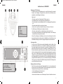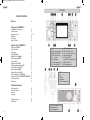
1
manual_MX-10_v1-7:RoadCOM manual.qxd 12/17/2014 8:45 AM Page 1
Full Multi Norm / -hp
Bedienungsanleitung
Operating Instruction
Manual de instrucciones
Manuale d’istruzioni
Mode d’emploi
Handleiding
Downloaded from www.cbradio.nl
manual_MX-10_v1-7:RoadCOM manual.qxd 12/17/2014 8:45 AM Page 2
Bedienelemente
INHALTSVERZEICHNIS
Bedienelemente
3-4
Inbetriebnahme des TEAM MX-10
Montage einer CB-Funkantenne
Antennenanschluss
Montage des Gerätes im Fahrzeug
Mikrofon
Stromversorgung
Lieferumfang
5
5
5-6
6
6
6
Funkbetrieb mit dem TEAM MX-10
Einschalten [OFF/VOL]
Kanalwahl
Senden
Rauschsperre [ASQ/SQ]
Modulationsarten [Mode]
Kanalsuchlauf [SCAN]
Tastatursperre [F/
]
Zweikanalüberwachung [DW]
LCD-Hintergrundbeleuchtung [LCR]
Vorrangkanal 9/19 [9/19]
Speicherkanäle [MEM]
automatische Geräuschunterdrückung [ANL]
Empfangssignal-Empfindlichkeit [RF GAIN]
Umschaltung der Frequenznorm [ DE/PL/EC/EU/EI/UK]
Anschlussbuchse für einen externen Zusatzlautsprecher
internes Signal-Meter
7
7
7
7
8
8
8
8
9
9
9
9
9
10
10
10
1. LCD
2. ASQ - automatische
Rauschunterdrückung
3. MODE - Betriebsartenumschalter
4. SCAN - Kanalsuchlauf
5. F/
- Tastatursperre
6. DW - Zweikanalüberwachung
7. LCR - Hintergrundbeleuchtung
8. 9/19 - Prioritätskanäle
9. MEM - Speicherkanäle
10.
11.
12.
13.
OFF/VOL - Ein/Aus, Lautstärke
ANL - autom. Geräuschfilter
Kanalwahldrehschalter
außen: RF Gain Empfangsempfindlichkeit
innen: Squelch manuelle Rauschunterdrückung
14. RX/TX Kontrollleuchte
15. 6-Pin Mikrofonanschluß
Hinweise
Sicherheitshinweis
Allgemeine Hinweise
Service
Konformität
Entsorgung
Kanalfrequenztabelle
Technische Daten
2
11
11
11
11
11
54
55
3
manual_MX-10_v1-7:RoadCOM manual.qxd 12/17/2014 8:45 AM Page 4
Deutsch
Deutsch
Inbetriebnahme des TEAM MX-10
Montage einer CB-Funkantenne
Die Wahl der Antenne und des Montageortes ist von großer Bedeutung für die maximale
Reichweite Ihrer Funkanlage. Die folgenden Kriterien sollten Sie bei der Wahl des Antennenstandortes und der Montage berücksichtigen.
16.
17.
18.
19.
20.
PTT
UP
DOWN
Mikrofon
6-Pin Mikrofonstecker
Allgemein gilt:
> Die Antenne muss für den Funkbetrieb auf 27 MHz geeignet sein.
> Der Standort der Antenne sollte möglichst hoch und unverbaut sein.
> Das Antennenkabel muss unbeschädigt, und die Stecker ordnungsgemäß angeschlossen
sein.
> Das Antennenkabel darf nicht zu stark geknickt werden.
> Antennen mit einer größeren mechanischen Länge erzielen bessere Reichweiten.
Bei der Montage von Mobilantennen ist folgendes zu beachten:
> Die Antenne sollte in der Mitte eines größeren Karosserieteils montiert werden.
> Der Antennenfuß von Mobilantennen sollte möglichst guten Kontakt zu einer metallisch gut
leitenden Fläche des Karosseriebleches haben.
Außer der "festen Montage" einer Mobilantenne, bei der ein Loch in die Karosserie Ihres Fahrzeuges gebohrt werden muss, gibt es noch weitere Möglichkeiten, z. B. die Dachrinnen- oder
Kofferraumdeckel-Montage, sowie die Befestigung mit Magnetfuß oder Scheibenantenne.
Antennenanschluss
Der PL-Stecker (Typ: PL259) des Antennenkabels (Koaxialkabel) wird mit der Buchse (24) an
der Geräterückseite verbunden. Für eine einwandfreie Verbindung muss der Überwurf des
Steckers gut festgedreht werden. Ebenso ist auf eine ordentliche Verbindung des Antennenkabels mit dem Antennenfuß zu achten. Nicht einwandfreie Verbindungen können zu einem
Defekt des Gerätes führen und die Funkreichweite erheblich verringern. Die Antennenanlage
(nicht im Lieferumfang enthalten) sollte sehr gut an das Funkgerät angepasst sein, ansonsten
wird ein Teil der Sendeleistung an der Antenne reflektiert und nicht abgestrahlt. Das führt
ebenfalls zu einer geringeren Reichweite der Funkanlage. Die Anpassung der Antenne erfolgt
durch Längenabgleich des Antennenstrahlers bzw. seiner Anpassungsvorrichtung auf ein
minimales Stehwellenverhältnis, welches mit einem Stehwellenmessgerät (z.B. TEAM SWR
1180 P) gemessen werden kann. Das Stehwellenmessgerät muss nach der Messung wieder
aus der Antennenleitung entfernt werden.
23. Anschluss für ext. Lautsprecher;
3,5 mm Klinke
24. PL-Antennenbuchse
25. Stromversorgungskabel
Montage des Gerätes im Fahrzeug
Das Gerät kann mit dem beiliegenden Montagebügel-Set z.B. unter dem Armaturenbrett
befestigt werden. Bei der Wahl der optimalen Position für die Montage des Gerätes in Ihrem
Fahrzeug sind auch die folgenden Kriterien zu berücksichtigen:
> keine Beeinträchtigung der Verkehrssicherheit,
> gute Erreichbarkeit der Bedienelemente,
> ausreichende Luftzirkulation, um eine Überhitzung des Gerätes im Sendefall zu verhindern.
4
5
manual_MX-10_v1-7:RoadCOM manual.qxd 12/17/2014 8:45 AM Page 6
Deutsch
Deutsch
Funkbetrieb mit dem TEAM MX-10
Darüber hinaus sollten Sie auch sicherstellen, dass die LCD-Kanalanzeige (1) gut ablesbar
ist. Bei direkter Sonneneinstrahlung kann die Lesbarkeit der Anzeige beeinträchtigt werden.
Die günstigste Montageposition sollte vor dem endgültigen Einbau überprüft werden. Mit Hilfe
des beiliegenden Montagebügels, ist eine schnelle Montage bzw. Demontage an verschiedenen Stellen im Fahrzeug möglich.
Mikrofon
Das Mikrofon wird mit dem 6-poligen Stecker in die Mikrofonbuchse (15) an der linken Gerätefrontseite angeschlossen. Ohne Mikrofon ist kein Sende- oder Empfangsbetrieb möglich.
Die Mikrofonbuchse ist nach GDCH-Standard angeschlossen:
PIN 1 Modulation
PIN 3 PTT
PIN 5 Masse
PIN 2 Lautsprecher
PIN 4 Up/Down
PIN 6 +12 Volt
Ansicht von der Lötseite der
Mikrofonbuchse bzw. Vorderansicht des Mikrofonsteckers
Mit dem MX-10 wird das Standardmikrofon geliefert. Dieses Mikrofon ist optimal für das MX-10
geeignet.
Stromversorgung
Vor dem Anschluss der Stromversorgung schalten Sie das Gerät aus, indem Sie den kombinierten Ein/Aus-Lautstärkeregler (10) [VOL] bis zum Anschlag nach links drehen.
Verbinden Sie die beiden blanken Anschlüsse am Ende des Kabels mit dem Bordnetz
Ihres Fahrzeuges. Die Betriebsspannung kann 12 V oder 24 V betragen. Das Stromversorgungskabel sollte möglichst weit von störenden Aggregaten verlegt werden. Achten Sie beim
Anschluss auf die richtige Polarität:
SCHWARZ
wird mit "-" ( = MINUS / Masse ) des KFZ verbunden.
ROT
wird mit "12/24 Volt +" ( = PLUS ) des KFZ/LKW-Bordnetzes verbunden.
Bei Verwendung von Dauerplus bleiben die letzten Einstellungen auch nach dem Ausschalten des Gerätes und dem Abstellen des Motors gespeichert.
Nachdem die Antenne, das Mikrofon und die Stromversorgung sorgfältig angeschlossen sind,
kann der Funkbetrieb aufgenommen werden.
Lieferumfang
1 x MX-10 Mobilfunkgerät
1 x UP/DOWN Mikrofon mit Halter
1 x abnehmbarer Zigarettenanzünder-Adapterstecker mit Sicherung
1 x Unterbau-Montagesatz
1 x Konformitätserklärung
1 x Bedienungsanleitung
6
Einschalten [OFF/VOL]
Vor dem erstmaligen Einschalten sollte der innere Ring des Doppelregelers (13) [SQ/RF
GAIN] bis zum Linksanschlag gedreht werden. Das Gerät wird eingeschaltet, indem Sie den
Lautstärkeregler (10) [OFF/VOL] nach rechts drehen. Die LCD-Anzeige leuchtet und das
Empfängerrauschen oder eine andere Station wird hörbar. Stellen Sie die gewünschte Lautstärke ein und passen die Rauschsperre an.
Alle Einstellungen, die beim Betrieb des Gerätes vorgenommen werden, bleiben nach dem
Ausschalten erhalten, solange die Stromversorgung nicht unterbrochen wird.
Kanalwahl
Die Kanäle können durch Drücken der Kanalwahltasten (17) [UP] und (18) [DOWN] am Mikrofon oder mit dem Kanalwahldrehschalter (12) eingestellt werden. In der Anzeige (1) wird die
Kanalnummer und die entsprechende Frequenz angezeigt. Während des Sendens kann kein
anderer Kanal eingestellt werden. Es kann nur auf übereinstimmenden Kanalnummern und
Modulationsarten mit der Gegenstation Funkbetrieb aufgenommen werden.
Senden
Zum Senden wird die im Mikrofon eingebaute Sendetaste (16) [PTT] gedrückt und für die
Dauer der Durchsage gehalten. Die Sendekontrollleuchte symbol in der LCD-Anzeige TX
erscheint. Die Balkenanzeige unten in der LCD-Anzeige zeigt die relative Sendeleistung an.
Das Mikrofon sollte aus ca. 5 cm Entfernung mit normaler Lautstärke besprochen werden. Zu
lautes oder zu leises Besprechen erschwert die Verständigung. Nach Beendigung der Durchsage muss die Sprechtaste (16) sofort wieder losgelassen werden, und das Gerät schaltet
auf Empfangsbetrieb zurück.
Rauschsperre [ASQ] / [SQ]
Das MX-10 ist mit einer manuellen [SQ] und automatischen Rauschsperre [ASQ] ausgerüstet. Das störende Rauschen, welches beständig auf dem Frequenzband zu hören ist, wird
durch die Rauschsperre unterdrückt.
Mit der manuellen Rauschsperrenunterdrückung [SQ] bestimmen Sie den Schwellpunkt
selbst. Am Linksanschlag ist die Rauschsperre ausgeschaltet. Durch Rechtsdrehen des
Rauschsperrereglers (13) [SQ] wird der Schwellpunkt zunehmend angehoben.
Wenn ein Signal auf dem Kanal präsent ist, öffnet die Rauschsperre und das Signal ist im
Lautsprecher zu hören. Bei zu kritischer Einstellung der Rauschsperre kann zeitweilig ein kurzes Rauschen auftreten, ohne dass sich eine Station auf dem Kanal befindet. Weiteres
Rechtsdrehen unterdrückt zunehmend schwache Stationen, aber auch stärkere Störsignale.
Bei einer zu festen Squelch-Einstellung kann es im Kanalsuchlauf-Betrieb zur Nichterkennung eines belegten Kanals kommen.
Das MX-10 verfügt ebenfalls über eine automatische Rauschperre [ASQ], welche durch
Drücken der Taste ASQ (2) am Gerät aktiviert wird. Der Schwellwert ist auf einen fixierten,
erprobten Wert eingestellt. Bei aktivierter automatischer Rauschperre erscheint das Symbol
ASQ in der Anzeige.
7
manual_MX-10_v1-7:RoadCOM manual.qxd 12/17/2014 8:45 AM Page 8
Deutsch
Modulationsarten [Mode]
Das MX-10 arbeitet in den Betriebsarten AM und FM.
Falls das Gerät auf dem aktuellen Kanal die Betriebsart AM akzeptiert, kann durch Drücken der
Mode-Taste (3) [MODE] zwischen AM und FM umgeschaltet werden. In der Anzeige erscheint,
das entsprechende Symbol (AM/FM).
In der Frequenznorm UK, der Full Multi Norm Gerätevariante, wird die Betriebsart FM nicht verändert, es wird zwischen den UK-Frequenzen und den CEPT-Frequenzen umgeschaltet.
Kanalsuchlauf [SCAN]
Bei aktivierter Funktion werden auf dem gewählten Frequenzband besetzte Kanäle gesucht.
Der Kanalsuchlauf funktioniert nur bei “geschlossener” Rauschsperre, d.h.
Bevor der Kanalsuchlauf gestartet wird, muss die manuelle Rauschsperre (13) [SQ], wie
unter Absatz 2 beschrieben, eingestellt werden. Bei offener Rauschsperre kann das Gerät die
Such- und Haltefunktion nicht erfüllen.
Durch kurzes Drücken der Suchlauftaste (4) [SCAN] startet der Kanalsuchlauf aufwärts zählend. Die aktivierte Scan-Funktion wird durch das Symbol SC angezeigt. Der Suchlauf bleibt
auf dem ersten belegten Kanal, auf dem die Rauschsperre durch Signalstärke automatisch
geöffnet wird, stehen. Er ist damit beendet, was mit dem Erlöschen des Symbols SC angezeigt wird.
Der Kanalsuchlauf wird vorzeitig beendet, durch Drücken der Kanalsuchlauftaste (4) [SCAN].
Tastatursperre [F/
]
Die Tastatursperre deaktiviert alle Funktionstasten mit Ausnahme der PTT-Taste am Mikrofon. Zum aktivieren bzw. deaktivieren der Funktion drücken Sie bitte die TastatursperrenTaste (5). Im aktiven Zustand erscheint in der Anzeige das Schlüsselsymbol
.
Zweikanalüberwachung [DW]
Mit dieser Funktion werden zwei ausgesuchte Kanäle überwacht. Damit diese Funktion ordnungsgemäß arbeiten kann, darf die Rauschsperre nicht geöffnet sein.
Wählen Sie zunächst den ersten Überwachungskanal aus mit dem Kanaldrehwahlschalter (12)
oder den Kanalwahltasten (17) [UP] und (18) [DOWN] am Mikrofon mit seiner Modulationsart.
Drücken Sie kurz die Taste (6) [DW], so dass das Symbol für die Zweikanalüberwachung DM
blinkend in der Anzeige erscheint. Wählen Sie dann mittels des Kanaldrehwahlschalters (12)
oder der Kanalwahltasten (17) und (18) am Mikrofon den zweiten Überwachungskanal mit ggf.
anderer Modulationsart aus. Drücken Sie dann erneut kurz die Taste (6) [DW], so dass das Symbol DM für die Zweikanalüberwachung nun dauerhaft in der Anzeige erscheint. Die Zweikanalüberwachung ist nun endgültig aktiviert.
Das Gerät springt nun einmal pro Sekunde zwischen den beiden Überwachungskanälen hin
und her, solange keiner der beiden belegt ist. Wenn ein Kanal belegt ist, was sich durch Öffnen der Rauschsperre äußert, bleibt das Gerät solange darauf stehen, bis die Rauschsperre
wieder schließt.
Zum Beenden der Zweikanalüberwachung, drücken Sie kurz die Taste (6) [DW].
Senden auf dem aktuellen Kanal ist möglich, beendet die Zweikanalüberwachung jedoch nicht.
8
Deutsch
LCD-Hintergrundbeleuchtung [LCR]
Die LCD-Hintergrundbeleuchtung kann durch jeweils kurzes Drücken der Taste [LCR] (7) zwischen 7 verschiedenen Farben umgeschaltet werden.
Die Hintergrundbeleuchtung kann auch komplett ausgeschaltet werden.
Vorrangkanal 9/19 [9/19]
Das Gerät verfügt in allen Versionen über die Vorrangkanäle 9 und 19. Durch einmaliges
Drücken der Vorrangskanaltaste (8) [9/19] wird der Kanal 9 eingestellt. Erneutes Drücken der
Taste stellt den Kanal 19 ein. Um zum ursprünglich gewählten Kanal zurückzukehren, Drükken Sie die Taste noch einmal.
Speicherkanäle [MEM]
Mit dem MX-10 können Sie 10 Kanäle der aktuellen Frequenznorm abspeichern und somit direkt
abrufen.
Programmieren von MEM-Kanälen:
1. Wählen Sie die gewünschte Frequenz, welche gespeichert werden soll.
2. Aktivieren Sie den Programmiermodus durch Drücken der Taste MEM (9). Es erscheint das
blinkende Symbol ME in der oberen linken Ecke der Anzeige.
3. Wählen Sie den MEM-Kanal (1-10), auf dem die gewünschte Frequenz gespeichert werden
soll.
3. Bestätigen Sie die Programmierung durch erneutes Drücken der Taste MEM.
Abrufen von programmierten MEM-Kanälen:
1. Drücken Sie die Taste F (5) gefolgt von der Taste MEM (9). Das Symbol RD blinkt oben links
in der Anzeige.
2. Wählen Sie den gewünschten MEM Kanal (1-10) mit Hilfe des Kanalwahlschalters (12).
3. Bestätigen Sie die Auswahl durch erneutes Drücken der MEM-Taste. Das Symbol M erscheint
in der linken oberen Ecke der Anzeige.
automatische Geräuschunterdrückung [ANL]
Die Funktion ANL (automatic Noise Limiter) reduziert den Anteil der möglichen Störgeräusche beim Signalempfang. Zum aktivieren bzw. deaktivieren der Funktion drücken Sie bitte
die ANL-Taste (11). Im eingeschalteten Zustand erscheint in der Anzeige das Symbol ANL.
Empfangsempfindlichkeit [RF Gain]
Signale, die aus unmittelbarer Nähe empfangen werden, können unter Umständen zu stark sein,
das Signal klingt verzerrt. Mit der RF-Gain Funktion kann das Empfangssignal abgeschwächt
werden.
Mit dem Außenring des Doppelreglers [SC/RF Gain] (13) wird die Empfangssignalstärke
reduziert durch Schwächung der Empfangsempfindlichkeit.
Keine Signal-Dämpfung erfolgt wenn der Regler bis zum Anschlag im Uhrzeigersinn gedreht
ist. Dies sollte für den normalen Betrieb die Standardeinstellung sein. Zunehmendes Drehen
entgegen dem Uhrzeigersinn verringert die Empfangsempfindlichkeit.
9
manual_MX-10_v1-7:RoadCOM manual.qxd 12/17/2014 8:45 AM Page 10
Deutsch
Deutsch
Umschaltung der Frequenznorm [DE/PL/EC/EI/UK]
Die Geräteversion MX-10 Full Multi Norm kann vom Benutzer auf eine der folgenden Normen
eingestellt werden:
Norm Kanäle und Frequenzen
Anzeige
DE 80 FM (26,565 - 27,405 MHz), 4 W / 40 AM (26,965 - 27,405 MHz), 4 W
DE
UK
UK 40 FM (27,60125 - 27,99125 MHz), 4 W / 40 FM (26,965 - 27,405 MHz), 4 W
EI
EI 40 FM (26,965 - 27,405 MHz), 4 W / 40 AM (26,965 - 27,405 MHz), 4 W
EC 40 FM (26,965 - 27,405 MHz), 4 W
EC
PL 40 FM (26,960 - 27,400 MHz), 4 W / 40 AM (26,960 - 27,400 MHz), 4 W
PL
Zum Ändern der aktuellen Norm, welche in der oberen linken Ecke der Anzeige erscheint,
halten Sie bitte die Tasten F (5) und MEM (9) während dem Einschalten des Gerätes gleichzeitig gedrückt. Wählen Sie die gewünschte Norm mit dem Kanalwahldrehschalter und schalten Sie das Gerät aus um die Einstellung zu speichern. Nach erneutem Einschalten arbeitet
das Gerät auf der eingestellten Frequenznorm.
Für die Erlaubnis und die Auflagen zum Betrieb der verschiedenen Normen in den einzelnen Ländern sehen Sie in den Gerätepass. Der Benutzer ist für die richtige Einstellung
der gültigen Norm im jeweiligen Land eigenverantwortlich.
Hinweis:
Die Ausführung MX-10 hp (Mono Band) ist fest auf 40 Kanäle AM/FM, 4 Watt eingestellt.
Anschlussbuchse für einen externen Zusatzlautsprecher
Das MX-10 hat an der Geräterückseite eine Klinkenbuchse (23) ( 3,5 mm ø ) zum Anschluss
für einen externen Lautsprecher mit 4 - 8 Ohm Impedanz ( z.B. TEAM TS-500 ). Bei 4 Ohm
sollte die Belastbarkeit des Lautsprechers 4 Watt betragen. Bei Anschluss des externen Lautsprechers wird der interne Lautsprecher abgeschaltet.
Internes Signal-Meter
Die interne Balkenanzeige SRF im LC-Display (1) zeigt die Empfangs- und Sendestärke des Signals an.
10
HINWEISE
Sicherheitshinweis
Bitte beachten Sie als KFZ-Fahrer beim Funkbetrieb auch die Bestimmungen der jeweils gültigen Straßenverkehrsordnung. Bei dem Betrieb des Gerätes wird Hochfrequenzenergie freigesetzt. Es muss daher ein entsprechender Sicherheitsabstand zur Antenne eingehalten werden.
Allgemeine Hinweise
Das Gerät ist vor Feuchtigkeit und Staub zu schützen. Das Gerät niemals an Orten aufbewahren, die einer starken Erhitzung und/oder direkter Sonneneinstrahlung ausgesetzt sein
könnten. Zur Gehäusereinigung ein weiches, fusselfreies Tuch verwenden. Zur Reinigung
niemals Lösungsmittel verwenden.
Service
Das Gerät darf nicht geöffnet werden. Eigenhändige Reparaturen oder Abgleich sind nicht
vorzunehmen, denn jede Veränderung, bzw. Fremdabgleich, können zum Erlöschen der
Betriebserlaubnis sowie der Gewährleistungs- und Reparaturansprüche führen. Bei Betriebsstörungen sollte das Gerät nicht benutzt werden. Trennen Sie in diesem Fall die Stromversorgung ab. Liegt ein Defekt vor, sollte auf jeden Fall der autorisierte TEAM-Fachhändler kontaktiert werden.
Konformität
Das CB-Mobilsprechfunkgerät TEAM MX-10 entspricht der europäischen R&TTE Direktive
und hält die europäischen Normen EN 300 135-2, EN 300 433-2, EN 301 489-1/-13 und EN
60950-1 ein. Die genauen Länderbestimmungen der verschiedenen Versionen entnehmen
Sie bitte dem beiliegenden Gerätepass.
Entsorgung
Bitte werfen Sie Ihr TEAM-Altgerät nicht einfach auf den Müll, sondern senden Sie Ihr Altgerät bitte portofrei zur fachgerechten Entsorgung an TEAM ein. TEAM wird anschließend die
umweltschonende Entsorgung Ihres Altgerätes für Sie kostenlos veranlassen.
- Änderung der technischen Daten und der Ausführung sind ohne Vorankündigung vorbehalten. -
11
manual_MX-10_v1-7:RoadCOM manual.qxd 12/17/2014 8:45 AM Page 12
English
English
Elements
TABLE OF CONTENTS
Elements
13
Setting up the TEAM MX-10
Installation of a CB antenna
Aerial Connection
Installation in the car
Microphone
Power source
Scope of Delivery
14
14
14 - 15
15
15
15
Operation of the TEAM MX-10
Switching on [OFF/VOL]
Channel selection
Transmitting
Squelch [ASQ/SQ]
Modulation Selection [Mode]
Channel scanning [SCAN]
Key Lock [F/
]
Dual watch function [DW]
LCD background illumination [LCR]
Priority Channel 9/19 [CH9/19]
Memory Channels [MEM]
Automatic Noise Limiter [ANL]
Receiving Signal Sensitivity [RF Gain]
Frequency Norm Selection [DE/PL/EC/EU/EI/UK]
External speaker jack
Signal meter
16
16
16
16
16
17
17
17
17
17
17
18
18
18
18
18
1. LCD
2. ASQ - automatic squelch
3. MODE - switch AM/FM
4. SCAN - channel scan
5. F/
- keylock
6. DW - dual watch
7. LCR - background light
8. 9/19 - priority channel
16.
17.
18.
19.
20.
9.
10.
11.
12.
13.
MEM - memory channel
OFF/VOL - On/Off, volume
ANL - automatic noise limiter
rotary channel selector
outer ring: RF GAIN
inner ring: SQ - manual squelch
14. RX/TX control LED
15. 6-Pin microphone jack
PTT
UP
DOWN
microphone
6-Pin microphone jack
Additional Information
Safety Instructions
General Precautions
Servicing
Conformity
19
19
19
19
Channel Frequencies
Specifications
54
55
23. jack for ext. speaker, 3,5 mm
24. PL antenna jack
25. power supply cable
12
13
manual_MX-10_v1-7:RoadCOM manual.qxd 12/17/2014 8:45 AM Page 14
English
English
Setting up the TEAM MX-10
Installation of a CB antenna
The antenna is an important part of a cb mobile radio system. The type of antenna and its
location has a great effect on the range of operation. Please consider the following criteria for
selecting the best location and installation of your antenna:
> Make sure that the antenna is designed for radio operation on 27 MHz.
> The location of the antenna should be as high as possible without any obstacles nearby.
> The aerial cable should not be damaged and the plugs should be properly connected.
> Make sure that the antenna cable is not bent too much.
> The bigger the mechanical size of the antenna, the higher the range of operation.
When you install a mobile antenna please note the following advices:
> The antenna should be fixed in the center of a bigger part of the coachwork.
> The mobile antenna coil should have the closest possible contact with a conducting metallic
surface of the bodywork of the car.
There are also some other possibilities to fix the antenna onto the car without the necessity
to drill a hole into the bodywork of your car, e.g. mounting the antenna onto the gutter, mounting the antenna onto a holder on the cover of the boot or using an antenna with a magnetic
foot or using a windscreen antenna.
For base-station operation we recommend a stationary antenna on the roof, for example the
TEAM ECO 050 or ECO 200.
> Please don't mount the CB antenna nearby a radio or TV antenna to prevent interference
of radio or TV reception.
> Keep an eye on power lines running along nearby when mounting the antenna on the roof.
" DANGER "
> The base-station antenna has to be connected via a lightning arrester.
> All connected cables including the antenna cable must not exceed a length of 3 m.
Aerial Connection
Before pressing the transmit key, a suitable aerial must be connected. The PL259 plug of the
aerial cable ( coax ) is connected to the SO239 socket (24) on the rear panel. Make sure, that
all plugs are firmly tightened and properly soldered. Unsatisfactory connections can damage
the radio and will reduce the range of operation.
The antenna should be matched with the radio, otherwise a part of the transmit power will be
reflected at the antenna and will not be radiated. This causes also a drop in the range of operation. The matching can be carried out by a length adjustment of the antenna radial for a minimal SWR ratio which can be measured by a SWR meter (e. g. TEAM SWR 1180P). After the
measurement, the SWR meter should be removed from the antenna line.
Installation in the car
When you want to install the unit into your car, you can install it below the dashboard with the
included mounting bracket set.
Always mount the transceiver where the switches are easily accessible. Please consider for
determining the correct mounting position:
14
> no interference of the roadworthiness,
> good access to the controls of the car,
> sufficient air circulation to prevent overheating of the radio in transmit mode.
Please consider that the readability of the LC display (1) depends on the angle of view. Also,
an intensive solar radiation affects the readability of the display. Please check the best position before the final installation.
Microphone
Plug the microphone-plug (20) into the 6-pin socket (15), located on the front panel. Pay
attention to proper placement. No transmission nor reception is possible without the microphone. The pin assignment of the GDCH standard microphone plug is given below:
PIN
PIN
PIN
PIN
PIN
PIN
1
2
3
4
5
6
Modulation
Loudspeaker
PTT
Up/Down
Ground
+12 Volt
Solder side view of the microphone connector or top view of the microphone plug.
The standard microphone , which is equipped with channel selector and signal tone keys, is
included with the MX-10. This microphone offers is the best selection for the MX-10.
Power source
Before connecting the unit to a suitable power source via the fused DC power cable (25), the
device must be switched off by turning the volume control (10) [OFF/VOL] counterclockwise
to the very end.
Then, connect the two naked leads at the end of the cable with the supply voltage of the
car/lorry battery. The unit is designed to operate with 12 volts or 24 volts and a negative
ground electrical system. Lay the cable as far as possible away from aggregates which can
cause interference. Pay attention to the correct polarity during the connection.
BLACK
RED
connect to - MINUS / ground of the car battery.
connect to 12/24 volts + PLUS of the car/lorry battery.
After proper connection of the microphone, the aerial and power source, radio operation can
be started.
Scope of Delivery
1 x MX-10 mobile radio
1 x UP/DOWN microphone with clamping holder
1 x detachable cigarette-lighter adapter plug with fuse
1 x under-dash mounting kit
1 x Declaration of Conformity
1 x manual
15
manual_MX-10_v1-7:RoadCOM manual.qxd 12/17/2014 8:45 AM Page 16
English
English
Operation of the TEAM MX-10
On/Off [OFF/VOL]
Before turning the radio on, set the squelch control (13) [SQ] to the lowest level by turning the
switch counterclockwise to the left.
Turn on the radio by turning the volume control (10) [OFF/VOL] clockwise. The LC display (1)
will illuminate. Adjust the receiver sound with the volume control to the desired level.
All settings are stored after the unit is switched off, as long as the power supply is not disrupted.
Channel selection
The channels of the selected frequency band can be selected by pushing the channel selector keys (17) [UP] and (18) [DOWN] at the microphone or with the rotary channel selector (12)
located on the front panel of the radio.
The channel number and frequency are displayed on the LCD (1).
No channel selection is possible while the radio is in TX mode. The channels are selected in
a consecutive order.
For communication with another CB radio, both transceivers must have selected the same
channel and the same modulation mode.
Transmit
To transmit, hold the PTT key (16) of the microphone. The RX/TX control LED (14) will light red
and the bar meter at the bottom of the display shows the relative transmit signal strength. For
best quality, speak at an average volume level, at a distance of 2-4 inches into the microphone
(19). Speaking too loudly will cause distortions and will make the signal difficult to understand.
While in transmit mode, no key entry is possible and the receiver is muted. To stop transmission,
release the PTT key (16) and the radio will revert to receive mode automatically.
Squelch [ASQ/SQ]
The strong background noise, which occurs always on free channels, can be suppressed by
the squelch function. The MX-10 has a manual squelch [SQ] (13) and an automatic squelch
[ASQ] available.
By turning the inner ring of the twin-rotary-selector clockwise, you increase the manual
squelch level gradually. It will increasingly suppress stronger interfering signals, as well as
weak stations.
The automatic squelch ASQ is activated by pushing the ASQ key [ASQ] (2). The squelch
level is fixed at a mean value. The symbol ASQ is visible on the LCD (1).
Mode selection [Mode]
The MX-10 operates in amplitude (AM) and frequency modulation (FM). Please note, that the frequency norm EC of the radio version MX-10 Full Multi Norm, operates in FM only.
If the unit accepts the modulation type AM on the actual channel, you can toggle between AM
and FM by pressing the mode key (3) [Mode].
The selected mode (AM/FM) is shown in the LCD.
With the frequency norm UK, which operates in FM only, you toggle between the EC and the
UK band remaining on FM.
16
Channel scanning [SCAN]
Channel scanning searches for signals on the selected frequency band. Make sure that the
squelch is closed since this function does not work with an open squelch.
To start/stop the scan function, push the scan button (4) [SCAN] briefly. The channels of the
current frequency band are searched in consecutive order. The scan symbol SC appears on
the LCD screen (1). Once a signal is detected, the scan function stops and the symbol SC in
the display will disappear.
To stop scanning before a signal has been found, press the scan button (8) [SCAN] once again.
Keylock [F/
]
Upon acitivated keylock function, all keys and functions, except for the PTT key (16) and
transmission, are blocked. To activated the function hold the keylock button [F/ ] until the
key symbol appears in the LCD (1).
To deactivate the key lock function press the key again.
Dual watch function [DW]
This function allows you to scan two channels for signals. Before activating this function make
sure that the squelch is closed.
Select the first channel to be scanned with the rotary channel switch (12) or the Up/Down
keys (17) [UP] and (18) [DOWN]. Then, briefly press the dual watch key (6) [DW]. The dual
watch symbol DW appears in the LCD (1) and the channel no. starts blinking.
Now, set the second channel to be monitored and press the dual watch key (6) [DW] again.
The radio will toggle between the two set channels until a signal is detected.
To stop the dual watch function, press the dual watch key [DW] (6 again.
LCD background illumination [LCR]
Turn the LCD background light either off or switched it between 7 colors by pressing the bakkground illumination key [LCR] (7).
Priority Channel 9/19 [9/19]
The MX-10 contains the priority channels 9 and 19. To toggle between the priority channels 9, 19
and the actual channel, use the priority channel key [9/19] (8).
Memory Channels [MEM]
The MX-10 allows to store and recall a maximum of 10 channels of the selected frequency band
on a separate memory bank.
Programming of MEM channels:
1. Select the channel/frequency to be stored.
2. Activated the programming mode by pressing the memory key MEM (9).
The symbol ME will blink in the LCD (1).
3. Confirm the programming by pressing the MEM key (9).
Recall of MEM channels:
1. Press the key F (5) first and then the key MEM (9). The symbol RD appears in the LCD.
2. Select the wanted MEM channel (1-10) with the rotary channel selector (12).
3. Confirm the selection by pressing the MEM key (9). The symbol M appears in the LCD.
17
manual_MX-10_v1-7:RoadCOM manual.qxd 12/17/2014 8:45 AM Page 18
English
English
Automatic Noise Limiter [ANL]
With the automatic noise limiter (ANL), the amount of noise on the selected frequency can
be reduced during reception. Activated/deacitvate the function by pressing the ANL key
(11). The active function is indicated by the symbol ANL in the LCD (1).
Receipt Signal Sensitivity [RF Gain]
Received signals from immediate sources can be too strong, the are distorted. With the RF Gain
function, the sensitivity of the received signal can be diminished by turning the outer ring of the
twin-rotary-selector [SQ/RF GAIN] (13) counterclockwise.
No damping of the signal sensitivity occurs when the selector is turn to the very right. This should
be the standard setting.
Norm Selection
With the MX-10 Full Multi Norm, the end-user can switch between the frequency norms DE,
EC, EI, PL and UK.
To enter the norm selection mode, hold both the keylock button [F/
] (5) and the memory
channel key [MEM] (9) while turning the radio on. Now, select the desired norm with the channel selector. The norm is indicated in the upper left corner of the display. To confirm your
selection, turn the radio off and back on again.
DE
EC
UK
PL
EI
80
40
40
40
40
FM
FM
FM
FM
FM
(26.565 - 27.405 MHz), 4 W / 40 AM (26.965 - 27.405 MHz), 4 W
(26.965 - 27.405 MHz), 4 W
(27.60125 - 27.99125 MHz), 4 W / 40 FM (26.965 - 27.405 MHz), 4 W
(26.960 - 27.400 MHz), 4 W / 40 AM (26.960 - 27.400 MHz), 4 W
(26.965 - 27.405 MHz), 4 W / 40 AM (26.965 - 27.405 MHz), 4 W
Regarding the permissions and restrictions of the individual norms in the various european
countries, please check the radio passport, which is included in the scope of delivery. The
user is solely responsible for the selection of the permissible norm in country of operation.
Additional information
Safety instruction
Drivers must keep attention to traffic rules when using the transceiver in a vehicle. While driving, operaters should use the VOX function, if available.
The unit radiates RF energy in transmit mode. Please keep an eye on safety distance to the
antenna.
General precautions
Protect the set from humidity and dust. Do not store at places where the temperature may
rise and cause damage - do not expose to direct sunlight. The set can be cleaned by wiping
with a soft cloth. Do not use chemical products to clean the set.
Servicing
The device must not be opened. Independent repairs or adjustment must not be carried out,
since each modification or unauthorized intervention will cancel warranty and repair claims.
Do not use the set if it seems not to function correctly. Disconnect the set in this case from
the DC power source immediately. If there is a defect, the authorized TEAM specialist dealer or TEAM must be contacted in every case.
Conformity
The CB mobile transceiver TEAM MX-10 complies to the European directive R&TTE and
meets the European standards EN 300 135-2, EN 300 433-2, EN 301 489-1/-13 and EN
60950-1.
The specific regulations of the different versions in the different european countries can be found
in the radio passport that is included in this manual.
Specifications are subject to change without any prior notice or obligation on the part of the manufacturer.
Note:The version MX-10 hp (mono band) is fixed to 40 channels AM/FM, 4 Watts only.
External speaker jack
The MX-10 is equipped with a 3.5 mm jack socket (24) at the rear panel to connect an external
speaker of 4-8 ohm impedance. At 4 ohms the speaker load can be 4 watts (e.g. TEAM TS-500).
When the external speaker is connected, the internal speaker will be switched off.
Signal meter internal
The bar meter in the LCD window shows the signal strength of the transmitted and received
signals.
18
19
manual_MX-10_v1-7:RoadCOM manual.qxd 12/17/2014 8:45 AM Page 20
Español
Español
Elementos
ÍNDICE
Elementos
21
Instalación
Instalación de una antena CB
Conexión aérea
Instalación en el coche
Micrófono
Fuente de alimentación
Contenido de la entrega
22
22
22 - 23
23
23
23
Funcionamiento del TEAM MX-10
Encendido [OFF/VOL]
Selección de canal
Transmisión
Silenciador [ASQ/SQ]
Selección de modulación AM/FM [Mode]
Exploración de canal [SCAN]
Bloqueo [F/
]
Función doble escucha [DW]
Iluminación de fondo LCD [LCR]
Canal prioritario 9/19 [9/19]
Memoria de canal [MEM]
Limitador automático de ruido [ANL]
RF Gain [RF GAIN]
Tipos de modelo [DE/PL/EC/EU/EI/UK]
Jack de altavoces externos
S Meter
24
24
24
24
24
25
25
25
25
25
26
26
26
26 - 27
27
27
1. LCD
2. ASQ - squelch automático
3. MODE - interruptor AM/FM
4. SCAN - escaneo de canal
5. F/
- bloqueo
6. DW - doble escucha
7. LCR - iluminación LCD
8. 9/19 - canal prioritario
16.
17.
18.
19.
20.
9.
10.
11.
12.
13.
MEM - canal de memoria
OFF/VOL - On/Off, volumen
ANL - limitador automático de ruido
selector de canal rotatorio
anillo exterior: RF GAIN
anillo interior: SQ - squelch manual
14. RX/TX control LED
15. 6-Pin toma de micrófono
PTT
UP
DOWN
micrófono
6-Pin toma de micrófono
Información adicional
Instrucciones de seguridad
Precauciones generales
Revisión
Conformidad
27
27
27
27
Tabla de canales y frecuencias
Características técnicas
54
55
23. toma para altavoz externo, 3,5 mm
24. PL toma de antena
25. cable de alimentación
20
21
manual_MX-10_v1-7:RoadCOM manual.qxd 12/17/2014 8:45 AM Page 22
Español
Español
Instalación del TEAM MX-10
Instalación de una antena CB
La antena es una de las partes más importantes del equipo, siendo la clase de antena utilizada la que determina el alcance del funcionamiento. Para seleccionar el lugar y la instalación apropiada de ésta le aconsejamos que sigan los siguientes criterios:
> Asegúrese que la antena esté diseñada para instalación de radio de 27 MHz.
> Coloque la antena lo más alto posible y sin que haya ningún obstáculo, despejada al máximo.
> El cable aéreo debe estar en buen estado y los conectores conectados satisfactoriamente.
> Asegúrese que el cable de la antena no esté muy doblado ni haciendo demasiados ángulos.
> Cuanto más grande sea el tamaño físico de la antena, mayor será el rendimiento del equipo.
Al instalar la antena móvil, por favor siga los siguientes consejos:
> Fijar la antena en el centro de la parte más grande de la carrocería.
> Colocar la bobina de carga de la antena lo más cerca posible a la superficie metálica conductora de la carrocería del coche.
Existen otras posibilidades para fijar la antena en el coche sin necesidad de taladrar la carrocería, como por ejemplo, montando la antena en el canalillo, en el maletero, o utilizando la
antena con base magnética o antena de cristal.
Para el buen funcionamiento de la estación de base, le recomendamos una antena estacionaria de techo, como por ejemplo el TEAM ECO 050 o ECO 200.
> Para prevenir interferencias en recepción de radio o TV, no montar la antena CB cerca de
una antena de radio o de TV.
> Al montar la antena en el techo hay que tener cuidado con las líneas eléctricas que estén
cerca. "DANGER"
> La antena de estación de base se ha de conectar, a ser posible, a un pararrayos o descargador.
> Todos los cables conectados, incluyendo el cable de la antena, no pueden superar los 3m
de longitud.
Conexión aérea
Antes de pulsar el botón de transmisión, conectar la antena adecuada. El conector PL259 del
cable (coaxial) se conecta al conector SO239 (24) en el panel trasero. Asegúrese que todas
las clavijas estén apretadas y soldadas correctamente, ya que si las conexiones no se realizan debidamente podrían dañar la radio y reducir el alcance del equipo.
Una vez instalados equipo y antena, deberá medirse el R.O.E. (SWR) para un correcto funcionamiento del conjunto. Una R.O.E. (SWR) elevada disminuye la potencia radiada y podría
causar daños en la parte final (transistores).
Instalación en el coche
Para ajustar el equipo en su coche, puede utilizar la abrazadera que se incluye por debajo
del salpicadero, o insertarla en un slot mediante el soporte también incluido. Montar siempre
el transmisor en un lugar de fácil acceso a los conectores. Otros puntos importantes para
realizar el montaje correcto son:
22
> que no haya interferencias técnicas,
> tener buen acceso a los controles del coche,
> que haya una circulación de aire suficiente para prevenir el recalentamiento de la radio en
modo transmisión.
Hay que tener en cuenta que el indicador LC (1) sólo se puede leer desde un cierto ángulo.
Una radiación solar intensiva podría afectar a la legibilidad del indicador. Por eso, se recomienda comprobar la posición adecuada antes de la instalación final. La emisora se puede
fijar fácilmente en el coche en diferentes posiciones utilizando la abrazadera que se incluye.
Micrófono
Enchufar el micrófono (19) en el conector de 6 pin (15) del panel frontal. Hay que tener en
cuenta que sólo funcionará en un sólo sentido. Sin el micrófono no es posible ninguna transmisión o recepción. La asignación de los pins de la clavija estándar GDCH es la siguiente:
PIN 1 Modulación
PIN 2 Altavoces
PIN 3 PTT
PIN 4 Arriba/ Abajo
PIN 5 Tierra
PIN 6 +12 Voltios
Vista lateral soldadura del conector de micrófono o vista superior de la clavija de micrófono.
El micrófono estándar equipado con selector de canales y tono de señal está incluido en el
MX-10, puesto que es el más adecuado para esta unidad.
Fuente de alimentación
Antes de conectar la fuente de alimentación al cable de corriente DC, el dispositivo debe
estar desenchufado. Para ello girar la tecla de control de volumen (10) [OFF/VOL] en el sentido contrario a las agujas del reloj hasta que se pare y se oiga un sonido de desconexión.
Conectar los dos cables descubiertos a los 12 o 24 voltios DC de la batería del coche. Esta
unidad esta diseñada para operar con un sistema eléctrico negativo a masa. Tender el cable
lo más lejos posible del conjunto, ya que puede producir interferencias. Vigilar la polaridad
correcta durante la conexión.
BLACK (Negativo) conectar a - MINUS / tierra de la batería del coche.
RED (Positivo)
conectar a 12/24 voltios + PLUS de la batería del coche.
Si la alimentación no está desconectada después de apagar el motor, los últimos ajustes se
guardarán hasta que la unidad se apague.
Contenido de la entrega
1 x MX-10 radio movíl
1 x Micrófono UP/DOWN con soporte
1 x pack de baterías
1 x cargador
1 x manual
23
manual_MX-10_v1-7:RoadCOM manual.qxd 12/17/2014 8:45 AM Page 24
Español
Español
Funcionamiento del TEAM MX-10
Encendido [OFF/VOL]
Antes de conectar la unidad, establecer el control de silenciador (13) [SQ] hasta el tope en
sentido contrario de las agujas del reloj y siempre sin activar el interruptor interno. El dispositivo se enciende con el control del volumen (10) [OFF/VOL] girando en el sentido de las
agujas del reloj. Los símbolos aparecen en el indicador LC (1) y la luz posterior LCD se
encenderá. Ajustar el sonido del altavoz con el control de volumen al nivel deseado.
Todos los ajustes que se hagan durante la operación del transmisor quedarán memorizados
después de que la unidad se apague y mientras no se interrumpa el suministro de energía.
Selección de canal
Todos los canales se pueden seleccionar pulsando los botones de selector de canal (17) [UP]
y (18) [DOWN] en el micrófono, o bien girando el selector rotatorio de canal (10) del panel
frontal hasta encontrar el canal deseado. El número de canal y la frecuencia de canal se indicarán en la ventana del LCD (1).
No es posible seleccionar un canal mientras la radio esté en modo TX. Para comunicaciones
con una estación complementaria CB ambos transmisores se deben ajustar al mismo canal
y al mismo tipo de modulación.
Transmisión
Para transmisión pulsar y mantener el botón (16) [PTT] del micrófono (19). Durante la transmisión, el control LED (14) se iluminará en rojo. La sensibilidad del micrófono se ha ajustado
para hablar a una distancia de 2-4 pulgadas (equivalente a 20 cms) . Si se habla en un tono
elevado se pueden producir sobremodulaciones. Mientras el ajuste esté en modo de transmisión, no habrá ninguna entrada posible de botón y el auricular permanecerá en silencio. Al terminarse la transmisión soltar el botón PTT (16) y el aparato volverá al modo recepción.
Silenciador [ASQ/SQ]
El ruido estridente de fondo que se suele producir en canales libres se puede suprimir con la
función de silenciador. Girando poco a poco el control de silenciador manual (13) [SQ] en el
sentido de las agujas del reloj se puede llegar a encontrar un punto donde desaparezca el
ruido. Para ello se debería subir el control de silenciador lo suficiente hasta que se deje de oír
el ruido de fondo de un canal no usado. Girando el control en el sentido de las agujas del reloj
se suprimirán notablemente tanto las señales de interferencia como las estaciones débiles.
Para activar el silenciador automático ASQ se puede pulsar el botón ASQ (2).
La función de silenciador automático está ajustada a un valor interno fijo.
Selección de modulación [Mode]
El MX-10 puede funcionar en modulación AM o FM. Ésta se puede cambiar pulsando el botón
(3) [Mode] entre los tipos de modulación AM y FM. El modo seleccionado AM/FM se indicará
mediante el símbolo AM/FM.
24
Exploración de canal [SCAN]
Si esta función está activa, la unidad buscará los canales ocupados.
Como esta función no funciona con silenciador abierto, fijar el control de silenciador (13)
[SQ]. .
Pulsar levemente el botón (4) [SCAN] para empezar la exploración de canal. Ahora hay más
canales y el símbolo de exploración SC aparece en la pantalla LCD. La función de exploración se para en el próximo canal donde una señal enciende el silenciador. En este momento
se finaliza la operación que se indicará con la extinción del símbolo de exploración SC.
Si se produce una desactivación prematura de la función exploración, volver a pulsar el botón
(4) [SCAN].
Entonces el símbolo de exploración SC desaparecerá del indicador, y el canal actual será
aquel dónde el número de canal se quedó cuando se desactivó la función de exploración.
Bloqueo [F/ ]
Si pulsa el botón de bloqueo (5) [F /
] por 2 segundos, la función está activada. Esta función también vendrá indicada con el símbolo del botón
en la ventana del LCD. Ahora la
unidad ignorará cualquier entrada procedente de cualquier botón excepto el botón PTT (16).
Para desactivar la función de bloqueo, volver a pulsar el botón (19) [F /
] hasta el símbolo de botón
desaparecerá del indicador. Ahora los botones se volverán a activar.
Función doble escucha [DW]
Esta función permite controlar la actividad en dos canales al mismo tiempo. Antes de activar esta
función asegúrese de que el silenciador está próximo a los canales libres.
Primero seleccionar el canal de sondeo mediante el selector de canales (10) o los botones Arriba/ Abajo (17) [UP] y (18) [DOWN] en el micrófono, y su modulación. A continuación pulsar
brevemente el botón (6) [DW] para que el símbolo de temporizador dual DW aparezca en la ventana del LCD. Ahora seleccionar el segundo canal de sondeo. Después volver a pulsar brevemente el botón (6) [DW] para confirmación.
Si se recibe una señal en uno de estos canales que inician el silenciador, la unidad permanecerá en éste hasta que vuelva a estar libre.
Para desactivar la función de temporizador dual y permanecer en el canal actual, pulse el botón
de temporizador dual (6) [DW].
Iluminación de fondo LCD [LCR]
Pulsando el botón de iluminación LCD (7) [LCR] es posible cambiar el modo del color de iluminación de LCD entre siete colores y desactivar la iluminación LCD.
Canal de Prioridad 9/19 [9/19]
La MX-10 dispone de los canales de prioridad 9 y 19. El canal de prioridad 9 se selecciona
pulsando la tecla (8) [9/19] una vez.
Para seleccionar el canal de prioridad 19, pulse la tecla (8) [9/19] una otra vez.
Para volver al canal anterior, si es el canal 19 el que está seleccionado pulse la tecla (8)
[9/19] una vez, y si es el 9, púlsela dos veces.
manual_MX-10_v1-7:RoadCOM manual.qxd 12/17/2014 8:45 AM Page 26
Español
Español
Memoria de canal [MEM]
Es posible guardar y recuperar 10 canales de la banda de frecuencia actual en un banco de
memoria (MEM 1-10) independiente.
Programación de los canales MEM
1. Seleccione el canal / frecuencia que desea almacenar.
2. activado el modo de programación pulsando la tecla MEM memoria (9). El símbolo ME
parpadeará en la pantalla LCD (1).
3. Confirme la programación pulsando la tecla MEM (9).
Recuperar de canales del MEM:
1. Pulse la tecla F (5) y luego la tecla MEM (9). El símbolo RD aparece en la pantalla LCD (1).
2. Seleccione el canal MEM deseado (1-10) con el selector de canal rotatorio (10).
3. Confirme la selección pulsando la tecla MEM (9). El símbolo M aparece en la pantalla LCD.
Para regresar al canal original, pulse el botón MEM.
Limitator automático de ruido [ANL]
Con el limitador de ruido automático (ANL), la cantidad de ruido de la frecuencia seleccionada se puede reducir durante la recepción. Active/desactive la función pulsando la tecla ANL
(11). La función activa se indica mediante el símbolo ANL en el LCD (1).
Sensibilidad de la señal de recepción [RFG]
Las señales que se reciben de las inmediaciones, pueden ser a veces demasiado y distorsionan la señal. Es una ventaja para debilitar las señales muy fuertes, ya que éstas pueden
ser difíciles de entender a veces debido a la distorsión pesada. Mediante el control de [RFG]
(13) la intensidad de la señal recibida se reducirá en un debilitamiento de la sensibilidad del
receptor. No hay atenuación de la señal tiene lugar cuando se gira la perilla en sentido horario hasta que se detenga. Esto debe ser para el funcionamiento normal de la opción predeterminada. Girando hacia la izquierda reduce la sensibilidad del receptor.
Tipos de modelo
El modelo MX-10 Full Multi Norm se puede entregar en diferentes versiones con diferentes
canales, tipos de modulación y potencia de transmisión.
DE
EC
UK
PL
EI
80
40
40
40
40
FM
FM
FM
FM
FM
(26.565 - 27.405 MHz), 4 W / 40 AM (26.965 - 27.405 MHz), 4 W
(26.965 - 27.405 MHz), 4 W
(27.60125 - 27.99125 MHz), 4 W / 40 FM (26.965 - 27.405 MHz), 4 W
(26.960 - 27.400 MHz), 4 W / 40 AM (26.960 - 27.400 MHz), 1 W
(26.965 - 27.405 MHz), 4 W / 40 AM (26.965 - 27.405 MHz), 4 W
Para entrar en el modo de selección de la norma, mantenga pulsado tanto el botón de bloqueo de teclas [F/
] (5) y la tecla de canal de memoria [MEM] (9) mientras enciende la
radio. Ahora, seleccione la norma con el selector de canales (10). La norma se indica en la
esquina superior izquierda de la pantalla LCD (1). Para confirmar su selección, apague la
radio y vuelva a encenderla.
En relación con los permisos y las restricciones de las normas individuales en los varios
países europeos, compruebe por favor el pasaporte de radio, que se incluye en el
alcance de la entrega. El usuario tiene la responsabilidad exclusiva de la configuración
correcta de la norma, válida en el país.
El tipo MX-10 -hp (banda de mono) sólo funciona con los canales 40 CEPT AM/FM. La
potencia de transmisión es 4 W.
Jack de altavoces externos
El MX-10 está equipado con una toma jack de 3,5 mm (23) en el panel posterior para conectar un altavoz externo de impedancia de 4 - 8 Ohm. A 4 Ohms la carga de altavoz puede ser
de 4 watios (p. Ej. TEAM TS-500). Cuando los altavoces externos estén conectados, quedan
silenciados los altavoces internos.
S-Meter
El S-Meter de la pantalla consta de 5 barras para visualizar el nivel de recepción y el nivel de
potencia radiada.
Información adicional
Instrucciones de seguridad
Los conductores deberán obedecer las normas de circulación en todo lo que respecta al uso
del transmisor en un vehículo, por lo que deberían utilizar un dispositivo para operación de
radio manos libres mientras conducen, como por ejemplo la función VOX o un conjunto de
micrófono manos libres como el TEAM DM-106VOX.
La unidad irradia energía RF en modo transmisión. También tengan en cuenta la distancia
de seguridad respecto a la antena.
Precauciones generales
Proteger el equipo de la humedad y el polvo. No almacenar en lugares donde se produzcan
aumentos de temperatura y se pueda dañar, como por ejemplo no exponerlo al sol. El equipo se puede limpiar con un trapo suave sin utilizar ningún tipo de producto químico.
Revisión
No se puede abrir el aparato, ni realizar reparaciones o ajustes posteriores, ya que cada modificación o intervención no autorizada dará como resultado la cancelación del permiso de explotación y la pérdida de garantía. No utilizarlo si parece que no funciona bien. En este caso, desconectar inmediatamente el equipo de la fuente de alimentación DC. En caso de encontrarse
algún defecto, podrán contactar con el especialista autorizado o el equipo TEAM.
Conformidad
El transmisor móvil CB TEAM MX-10 cumple con todas las directrices Europeas R&TTE y
estándares Europeos EN 300 135-2, EN 300 433-2, EN 301 489-1/-13 und EN 60950-1.
26
27
manual_MX-10_v1-7:RoadCOM manual.qxd 12/17/2014 8:45 AM Page 28
Italiano
Italiano
Elementi
INDICE
Elementi
29
Installazione del Team MX-10
Installazione di un'antenna Cb
Connessione volante
Installazione sull'auto
Microfono
Alimentazione
Ambito di fornitura
30
30
31
31
31
31
Funzionamento dell'apparato Team MX-10
Accensione [VOL/Off]
Selezione canale
Trasmissione
Squelch [ASQ/SQ]
Selettore di Modalità [MODE]
Tasto scansione canali [SCAN]
Tasto blocco [F/
]
Dual Watch o tasto blocco [DW]
Retroilluminazione schermo LCD [LCR]
Priorità canale 9/19 [9/19]
Canali di memoria [MEM]
Limitatore automatico di rumore [ANL]
RF-Gain
Tipologia Modelli [DE/PL/EC/EU/EI/UK]
Presa esterna per altoparlante
Presa esterna per misuratore di segnale
32
32
32
32
33
33
33
33
34
34
34
34
34
34
35
35
1. LCD
2. ASQ - squelch automatico
3. MODE - interruttore AM/FM
4. SCAN - scansione canali
5. F/
- tasto blocco
6. DW - dual watch
7. LCR - retroilluminazione LCD
8. 9/19 - canale 9/10 prioritario
16.
17.
18.
19.
20.
9.
10.
11.
12.
13.
MEM - canale di memoria
OFF/VOL - On/Off, volumen
ANL - limitatore automatico di rumore
Interruttore a rotazione per selezione canale
anello externo: RF GAIN
anello interno: SQ - squelch regolazione
14. RX/TX control LED
15. Presa microfono a 6 Pin
PTT
UP
DOWN
Microfono
Presa microfono a 6 Pin
Informazioni supplementaria
Istruzioni di sicurezza
Precauzioni generali
Assistenza
35
35
35
Tabelle Canali & Frequenza
Caratteristiche
54
55
23. toma para altavoz externo, 3,5 mm
24. PL toma de antena
25. cable de alimentación
28
29
manual_MX-10_v1-7:RoadCOM manual.qxd 12/17/2014 8:45 AM Page 30
Italiano
Italiano
Installazione del Team MX-10
Installazione di un'antenna Cb
L'Antenna è una delle parti più importanti dell'applicazione. Il tipo di antenna e la sua posizione hanno una grande importanza sul funzionamento del sistema. Per favore considerare i
seguenti criteri di selezione della migliore posizione ed installazione della vostra antenna:
> Assicuratevi che l'antenna sia progettata per le operazioni radio a 27 Mhz
> La posizione dell'antenna deve essere tanto più alta possibile e senza ostacoli nelle
vicinanze.
> Il cavo volante non deve essere danneggiato e le spine devono essere collegate correttamente.
> Assicuratevi che il cavo dell'antenna non sia piegato con curve troppo strette.
> Tanto più è lunga l'antenna, maggiore è il rendimento nel funzionamento.
Quando installate un'antenna per CB, per favore seguite il seguente consiglio:
> L'antenna dovrebbe essere fissata al centro della parte più grande della carrozzeria(capote).
> L'antenna deve essere a massa con la parte metallica dell'automezzo.
Ci sono anche alcune alter possibilità per fissare l'antenna sulla macchina senza la necessità di forare la carrozzeria, per esempio montando l'antenna sulla gronda, montando l'antenna su appositi supporti, o usando un'antenna con una base magnetica.
Per operazioni da base fissa, raccomandiamo l'utilizzo di apposite antenna da base,montata
sul tetto dell'abitazione.
> Per favore non montare l'antenna CB vicino alla radio o ad un'antenna TV per prevenire
interferenze nella ricezione radio o TV.
> Controllate il buono stato della linea di alimentazione e delle "messe a terra",quando montate l'antenna sul tetto.
> L'antenna per stazione radio da base deve essere collegata con massa a terra.
> Tutti I cavi alimentazione collegati, compreso il cavo antenna non devono essere di lunghezza superiore ai 3m.
Connessione volante
Prima di premere il tasto di trasmissione, dev'essere stabilita un'adeguata connessione
volante. La spina PL259 del cavo (coassiale) è collegato alla presa SO239 (24) sul pannello
posteriore. Assicurarsi che tutti i connettori siano fermamente chiusi e correttamente saldati.
Connessioni inadeguate possono danneggiare la radio e ridurne di funzionamento.
L'antenna deve essere collegata alla radio, altrimenti una parte della trasmissione di potenza si rifletterà sull'antenna e non sarà irradiata. Ciò determina anche un calo nel numero di
operazioni. L'abbinamento antenna/linea/radio va verificato prima di trasmettere (tramite
Rosmetro interposto tra la radio e la linea, verificando il minimo rapporto SWR, ed eventualmente tarando l'antenna per arrivare ad un risultato ottimale). Dopo la misurazione della
SWR, il Rosmetro deve essere rimosso dalla linea di antenna.
30
Installazione sull'auto
Quando si vuole fissare la radio sulla vostra auto, potete fissarla sotto il cruscotto, con l'aiuto della staffa di montaggio inclusa, o inserirla in un alloggiamento autoradio utilizzando il
telaio incluso. Dovrete sempre montare il transceiver dove gli interruttori sono facilmente
accessibili. Altri importanti accortezze per la corretta posizione di montaggio sono:
> nessuna interferenza al veicolo,
> buon accesso ai controlli della vettura,
> sufficiente circolazione d'aria per evitare il surriscaldamento della radio nella modalità di
trasmissione.
Si prega di tener conto che l'LC Display (1) è ben leggibile solo da un certo punto di vista. Un
intenso irraggiamento solare può influenzare la leggibilità del display. Quindi, si raccomanda
di scegliere la migliore posizione prima dell'installazione finale. L'unità può essere facilmente fissata in diverse posizioni sull'auto utilizzando l'acclusa staffa di montaggio.
Microfono
Collegare il microfono (19) nei 6 piedini della presa (15) sul pannello anteriore. Noterete che
entrano solo in una modalità (obbligata). La trasmissione e la ricezione non sono possibili
senza il microfono. L'assegnazione dei pin della spina GDCH standard di microfono è riportata di seguito:
PIN 1 Modulazione
PIN 2 Altoparlante
PIN 3 PTT
PIN 4 UP/DOWN
PIN 5 Massa
PIN 6 6+12 Volt
Vista laterale del connettore del
microfono o vista superiore del
microfono plug-in.
Il microfono standard che è dotato di canale di selezione e di segnale acustico, è incluso nella
confezione del MX-10. Questo microfono è la soluzione migliore per il MX-10.
Alimentazione
Prima di collegare alimentazione al cavo con fusibile,verificare che la radio sia spenta, ruotando il controllo del volume (10) [OFF/VOL] in senso antiorario,fino a sentire il suono che ne
indica lo spegnimento.
Poi collegare i due conduttori spelati all'altra estremità del cavo, con il 12/24 volt DC della batteria del veicolo. L'unità è stata progettata per funzionare con un sistema elettrico terreno
negativo. Appoggiare il cavo, per quanto possibile, lontano da particolari, che possono causare interferenze. Guardare la corretta polarità durante la connessione.
NERO
Collegare a -MENO/ massa della batteria
ROSSO
Collegare a 12 Volts+ Più della batteria auto.
Dopo aver collegato correttamente il microfono, le parti volanti e la fonte di alimentazione, si
possono iniziare le operazioni radio.
Ambito di fornitura
1 x MX-10 radiomobile
1 x adattatore
1 x kit di montaggio di base
1 x manuale d'uso
1 x UP/DOWN microfono con il supporto per microfono
1 x sigaretta cavo adattatore con fusibile
1 x dichiarazione di conformità
31
manual_MX-10_v1-7:RoadCOM manual.qxd 12/17/2014 8:45 AM Page 32
Italiano
Italiano
Funzionamento dell'apparato Team MX-10
Accensione [VOL/OFF]
L'apparato si accende, ruotando il tasto controllo del volume (10) [VOL/OFF] in senso orario,
verso il centro posizione. Una volta acceso, i simboli appaiono sul display LCD (1) e la retroilluminazione LCD è accesa.
Regolare il livello del suono con il controllo del volume all'intensità desiderata.
Tutte le impostazioni, che sono effettuate durante il funzionamento del ricetrasmettitore, restano
memorizzate dopo che l'unità viene spenta, a condizione che l'alimentazione non sia interrotta.
Selezione canale
Tutti i canali possono essere selezionati premendo il tasto selezione canale (17) [UP] e (18)
[DOWN] sul microfono, o ruotando il selettore canale (12) [CHANNEL] sul pannello anteriore per il canale desiderato. Il numero del canale verrà visualizzato sul display LCD con grandi caratteri mentre la frequenza sarà visualizzata con piccoli caratteri. Non è possibile nessun tipo di selezione, mentre la radio è in modalità TX.
Per la comunicazione con altra stazione CB, gli stessi dovranno essere impostati sul medesimo canale.
Trasmissione
Per trasmettere mantenere premuto il tasto PTT (16) [PTT] sul microfono (19). Il LED RX/TX (14)
è rosso, e il misuratore a barre nella parte inferiore del display visualizza la relativa trasmissione
del segnale. La sensibilità del microfono (19) è stata tarata a dare buoni risultati parlando di
norma, ad una distanza di 5-10 cm. Parlare troppo forte potrebbe causare distorsioni del segnale e rendere difficile la comprensione. Mentre si è in modalità di trasmissione non vi è alcuna possibilità di modificare alcuna impostazione della radio e il ricevitore è disattivato. Al termine della
trasmissione rilasciare il tasto PTT (16) [PTT] e si ritorna alla modalità di ricezione.
Squelch [SQ] [ASQ]
La MX-10 dispone di un controllo squelch manuale [SQ] (13) e un controllo squelch automatico [ASQ] (2).
I forti disturbi di fondo, spesso riscontrabili sui canali liberi, possono essere soppressi con la
funzione squelch. Ruotando lentamente in senso orario il controllo squelch (13) [SQ] si potrà
trovare il punto dove i disturbi saranno eliminati. Fermare la rotazione del controllo squelch
quando ritenuto sufficiente il livello di soppressione disturbo. Girando in senso orario il soppressore di disturbo, si incrementa l'eliminazione di interferenze di segnale, cosa positiva
anche per stazioni deboli.
La MX-10 ha anche un squelch automatico [ASQ] (2), che si attiva premendo il pulsante ASQ
(2). Il valore di soglia è impostata su un determinato valore testato. Quando il squelch automatico l'icona ASQ appare sul display.
Selettore di Modalità [MODE]
Il MX-10 può lavorare in Modalità AM o FM.
Premendo il tasto (3) [MODE] puoi selezionare tra la modalità AM e FM. La modalità selezionata sarà indicata con il simbolo AM o FM.
32
Nella norma di frecuenza EC il MX-10 funziona solo su FM.
Nella norma di frecuenza UK il MX-10 funziona solo su FM. Premendo il tasto (3) [MODE] puoi
selezionare tra le frequenze UK e le frequenze CEPT.
Tasto scansione canali [SCAN]
Se questa funzione è attiva, l'unità ricerca i canali occupati.
Se questa funzione non lavora con lo squelch aperto.
Premere il tasto (4) [SCAN] brevemente per avviare la scansione dei canali. Ora i canali stanno cercando verso l'alto e il simbolo SC appare sullo schermo LCD. La funzione di scansione
si ferma sul prossimo canale su cui si apre un segnale dello squelch. Nel momento in cui la
scansione è terminata compare il simbolo SC.
Per una prematura disattivazione della funzione di scansione, spingere il tasto (4) [SCAN]. Poi
il simbolo SC scompare dal display, e il canale attuale sarà quello in essere prima della disattivazione della funzione di scansione.
Blocco tastiera [F/
]
Tutti i tasti sono disattivati ad eccezione del tasto PTT (16). Lo stato attivo è indicato da un
simbolo chiave sul display.
Dual Watch [DW]
Questa funzione consente di vedere l'attività su due canali alla volta. Prima di attivare questa funzione assicurarsi che la funzione dello squelch sia chiusa sui canali liberi.
Prima selezionare la prima ricerca canale tramite il selettore canale rotante (12) o il tasto UP (17)
e DOWN (18) sul microfono e la sua modulazione. Premere poi brevemente il tasto (6) [DW].
Ora seleziona il secondo canali e tenere premuto brevemente il tasto (6) [DW] ancora una
volta finchè il silmbolo DW appare costantemente ciò a significare che la funzione Dual Watch
è finalmente attivata.
Se in nessuna delle due ricerche canali viene ricevuto alcun segnale, l'unità passerà da un
canale all'altro 2 volte al secondo. Se in una di queste ricerche canale viene ricevuto un segnale,con lo squelch aperto, l'unità rimarrà su di essa fino a quando il canale è di nuovo libero.
Se si preme brevemente il tasto (6) [DW] un'altra volta, il simbolo DW lampeggerà ancora sul
display LCD.
Adesso potete selezionare una seconda ricerca canale attraverso il selettore canale rotatorio (8) o il tasto Up/Down (17) [UP] e (18) [DOWN] sul microfono e la sua modulazione. Quel
canale sul quale era l'unità.
Per disattivare la funzione Dual Watch e rimanere sul canale attuale premere brevemente il
tasto dual Watch (6). E' Possibile trasmettere sul canale attuale ma non è terminate la funzione Dual Watch. La disattivazione della funzione DW sarà tale quando il simbolo DW sarà
sparito dal display.
Retroilluminazione schermo LCD [LCR]
Premendo il tasto della retroilluminazione del display LCD (7) [LCR], puoi cambiare la modalità del retroilluminazione schermo tra 7 diversi colori.
La retroilluminazione può essere disattivato completamente.
33
manual_MX-10_v1-7:RoadCOM manual.qxd 12/17/2014 8:45 AM Page 34
Italiano
Priorità canale 9/19 [9/19]
La MX-10 è dotata di un canale prioritario 9 e 19. Il canale prioritario 9 è selezionato premendo il tasto (8) [9/19] una volta. Per selezionare il canale 19, premere il tasto (8)
[9/19] due volte.
Per ritornare al canale precedente, premere il tasto (8) [9/19] una volta, se è stato selezionato il canale prioritario 9, o due volte, se è stato settato il canale prioritario 19.
Italiano
Selezionare lo standard desiderato con il selettore del canale e spegnere il MX-10 per salvare
l'impostazione. Dopo il reset, il dispositivo funziona allo standard di frequenza impostata.
Per quanto riguarda i permessi e le limitazioni di diverse norme nei vari paesi europei, controlli prego il passaporto radiofonico, che è incluso nella portata della consegna. L'utente ha
la responsabilità esclusiva per l'impostazione corretta della norma.
Nota: MX-10 hp (EC CEPT) internamente è regolato a 40 AM/FM, 4 watt soltanto.
[MEM]
La MX-10, è possibile salvare 10 canali della norma frequenza corrente e recuperare.
Programmazione canali MEM:
1. Selezionare la frequenza desiderata da memorizzare.
2. Attivare la modalità di programmazione, premere il tasto MEM (9). Il simbolo ME lampeggia
sul display.
3. Selezionare il canale MEM (1-10) in cui la frequenza desiderata deve essere memorizzato.
4. Premere ancora il tasto MEM per confermare la programmazione.
Recupero canali MEM:
1. Premere il tasto F (5) tasto seguito dal tasto MEM (9). Il simbolo RD lampeggia sul display.
2. Selezionare il canale desiderato MEM (1-10) con il selettore del canale (12).
3. Confermare la selezione. Premere anocora il tasto MEM. Il simbolo M appare sul display.
Presa esterna per altoparlante
Il MX-10 è fornito di una presa da 3,5 millimetri (23) posta sul pannello posteriore per collegare un altoparlante esterno dall'impedenza di 4 - 8 Ohm. Per 4 Ohm di impedenza l'altoparlante può essere di 4 watt (ad esempio Team TS-500). Quando l'altoparlante esterno è collegato lo speaker interno sarà spento.
S-Meter interno
La SRF visualizzazione bar interno sul display LCD (1) indica la potenza di ricezione e trasmissione del segnale.
Limitatore automatica del rumore [ANL]
La funzione ANL (limitatore automatico di rumore) riduce l'eventuale rumore durante la ricezione del segnale. Per attivare o disattivare la funzione premere il tasto ANL (11). All'accensione, il simbolo ANL appare sul display.
Sensibilità di ricezione [RF Gain]
I segnali ricevuti da vicino può essere troppo forte in determinate circostanze, il segnale è
distorto. Con la funzione RF-Gain, il segnale ricevuto può essere attenuato.
L'anello esterno del doppio regolatore [SC/RF Gain] (13) la forza del segnale ricevuto viene
ridotto, indebolendo la sensibilità di ricezione.
No attenuazione del segnale si verifica quando il controller è girato completamente in senso
orario. Questo dovrebbe essere il predefinito per il funzionamento normale. Aumentando antiorario per diminuirlo la sensibilità del ricevitore.
Tipologia Modelli
L'apparato MX-10 può essere fornito in modelli diversi con differenti canali, tipi di modulazione e potenza di trasmissione:
DE
EC
UK
PL
EI
80
40
40
40
40
FM
FM
FM
FM
FM
(26.565 - 27.405 MHz), 4 W / 40 AM (26.965 - 27.405 MHz), 4 W
(26.965 - 27.405 MHz), 4 W
(27.60125 - 27.99125 MHz), 4 W / 40 FM (26.965 - 27.405 MHz), 4 W
(26.960 - 27.400 MHz), 4 W / 40 AM (26.960 - 27.400 MHz), 1 W
(26.965 - 27.405 MHz), 4 W / 40 AM (26.965 - 27.405 MHz), 4 W
La norma appare sul display, in alto a sinistra. Per modificare la norma attuale, tenere premuto
i itasti F (5) e MEM (9) contemporaneamente i pulsanti mentre si accende l'unità.
34
Informazioni supplementaria
Istruzioni di sicurezza
Gli autisti devono mantenere l'attenzione alle regole del traffico usando il ricetrasmettitore in
un veicolo. Gli autisti dovrebbero utilizzare un dispositivo per il funzionamento radiofonico a
mani libere (viva voce) mentre guidano, per esempio la funzione del VOX.
L'apparato, quando in modalità TX, irradia energia RF. Mantenere l'antenna ad una distanza
di sicurezza.
Precauzioni generali
Proteggere l'apparato da umidità e da polvere. Non immagazzinare nei punti dove la temperatura può aumentare e causare danni, per esempio al sole. L'apparato può essere pulito utilizzando un panno morbido. Non usare i prodotti chimici per pulire l'apparato.
Assistenza
L'apparato non deve essere aperto. Le riparazioni o regolazioni "fai da te" non devono essere effettuate, poiché ogni modifica o intervento non autorizzato provocherà l'annullamento del
permesso di utilizzo, della garanzia e renderà nulli i reclami. Non usare l'apparato se sembra
non funzionare correttamente. In questo caso staccare immediatamente l'apparato dalla
fonte di alimentazione. Se riscontrato un difetto, il rivenditore autorizzato/specializzato
Team,o Team devono essere avvisati con in ogni caso.
35
manual_MX-10_v1-7:RoadCOM manual.qxd 12/17/2014 8:45 AM Page 36
Français
Français
Contrôles
CONTENU
37
Contrôles
37
Mise en service du TEAM MX-10
Montage d'une antenne CB
Connexion de l'antenne
Montage dans la voiture
Microphone
Connexion de l'alimentation
Contenu de la livraison
38
38
39
39
39
39
Le fonctionnement de votre TEAM MX-10
Mise en marche [OFF/VOL]
Choix du canal
Emettre
Réglage du squelch [ASQ] / [SQ]
Choix de la modulation AM/FM [Mode]
Recherche des canaux [SCAN]
Verrouillage du clavier [F/
]
Contro de deux canaux [DW]
Illumination de l'afficheur LCD [LCR]
Canal 9/19 prioritaire [9/19]
Canaux de mémoire [MEM]
Réduction automatique du bruit [ANL]
Sensibilité du signal reçu [RF-Gain]
Espèces de modèles [DE/PL/EC/EU/EI/UK]
Connexion d'un haut-parleur externe
S-mètre interne
40
40
40
40
41
41
40
41
42
42
42
42
42
43
43
43
1. LCD
2. ASQ - squelch automatique
3. MODE - changement AM/FM
4. SCAN - recherche des canaux
5. F/
- verrouillage du clavier
6. DW - contro de deux canaux
7. LCR - illumination de l’afficheur
8. 9/19 - canale 9/19 prioritaire
16.
17.
18.
19.
20.
9.
10.
11.
12.
13.
MEM - canaux de mémoire
OFF/VOL - mise en marche, volume
ANL - réduction automatique du bruit
sélecteur rotatif de canaux
anneau extérieur: RF GAIN
anneau intérieur: SQ - squelch manuel
14. RX/TX LED de contrôle
15. prise microphone 6-Pin
PTT
UP
DOWN
microphone
connecteur de microphone
Informations additionnelles
Sécurité
Service
Tableaux Canaux & Frequence
Caractéristiques
43
43
54
55
23. connection pour haut-parleur externe, 3,5 mm
24. PL connection pour antenna
25. câble d’alimentation
36
37
manual_MX-10_v1-7:RoadCOM manual.qxd 12/17/2014 8:45 AM Page 38
Français
Français
Mise en service du TEAM MX-10
Montage d'une antenne CB
L'antenne est une partie très importante d'une station émettrice. Le type d'antenne et le lieu de
placement sont d'une grande importance pour la portée de votre émetteur récepteur. Les critères suivants sont déterminants pour le choix du lieu de placement et le montage de l'antenne:
> Faites attention de maintenir une certaine distance de sécurité à l'antenne à cause de la
radiation radioélectrique.
> Utilisez une antenne prévue pour 27 MHz.
> Choisissez l'endroit de l'antenne le plus haut que possible et le moins barré que possible.
> Le câble d'antenne ne doit être pas endommagé et les connecteurs doivent être raccordés
en bonne forme.
> Le câble d'antenne ne doit être coudé pas trop fort.
> Les antennes avec une longueur plus grande atteindrent une portée plus grande.
Prenez en considération les conseils suivants pour le montage des antennes mobiles:
> Placez l'antenne au milieu d'une part plus grande de la carrosserie.
> Le pied d'antenne mobile doit avoir le contact le mieux possible à une surface bien conductible de la carrosserie.
En dehors de la "montage fixe" de l'antenne mobile, qui demande la perçage d'un trou dans
la carrosserie de votre voiture, il y a des autres possibilités pour l'installation, par exemple l'utilisation d'une antenne de gouttière ou une antenne de fenêtre d'auto, la montage à un support sur le coffre ou la montage avec un pied magnétique.
Pour l'utilisation de l'appareil en station fixe, il est recommandé d'installer une antenne sur
comble stationnaire, par exemple TEAM ECO 050 ou ECO 200.
> Pour éviter des dérangements de la réception de radiodiffusion et de télévision il est
conseillé de ne pas placer l'antenne CB dans le voisinage immédiat de l'antenne de réception de radiodiffusion et de télévision.
> En installant d'une antenne sur comble il faut faire attention à des lignes à haute tension
qui passent à proximité. " DANGER DE MORT "
> L'antenne stationnaire doit être reliée à un dispositif de protection contre la foudre.
> Tous câbles reliés peuvent avoir une longueur de 3 m au maximum.
Connexion de l'antenne
Avant d'émettre il faut brancher une antenne à l'appareil. Le connecteur PL du type PL259
du câble d'antenne (coax) doit être raccordé à la prise d'antenne (24) placé au panneau arrière. L'écrou à raccord doit être vissé à fond pour une bonne jonction. Il faut également veiller
au bon raccordement du câble coaxial à l'antenne. Un mauvais raccord peut entraîner des
pertes et peut également endommager l'appareil.
En outre l'antenne doit être adaptée bien au émetteur récepteur, sinon une part de la puissance d'émission soit reflétée à l'antenne et ne soit pas rayonnée. Ça réduit aussi la portée
de l'appareil. L'accord d'antenne est réalisé par l'adaptation de la longueur du radiateur ou
son dispositif d'accord au minimum du rapport d'amplitude de puissance, qui peut être mesuré avec un mesureur de réflexions (par exemple TEAM SWR 1180P). Après avoir fini la mesure le mesureur de réflexions doit être enlevé du câble entre l'appareil et l'antenne.
38
Montage dans la voiture
Pour la fixation de l'appareil dans votre voiture, vous pouvez ou attacher l'un support de montage
livré sous le tableau de bord et visser l'appareil sur celui, ou insérer l'appareil dans l'ouverture
pour un radio en utilisant l'autre support livré. Veillez bien de fixer l'appareil à des endroits où les
éléments de commande soient bien accessibles et l'afficheur soit bien visible. Prenez aussi en
considération les aspects suivants pour le choix de la position dans votre voiture:
> aucune atteinte de la sécurité routière,
> bonne accessibilité des éléments de manipulation de la voiture,
> suffisante circulation d'air pour empêcher un surchauffage de l'appareil en cas de transmission.
Faites attention que l'affichage LCD (1) ne soit que bien lisible d'un angle certain. Une insolation forte peut aussi porter atteinte à la lisibilité de l'afficheur. Vérifiez la position plus avantageuse avant le montage définitif. A l'aide du support de montage livré vous pouvez installer
votre appareil facilement à plusieurs places dans la voiture.
Microphone
Brancher la fiche 6 broches du microphone (15) à la prise du microphone (19) placée sur la
partie gauche au panneau avant de l'appareil. Sans microphone, il n'est pas possible d'émettre ou de recevoir. Le connecteur du microphone est raccordé selon le standard GDCH:
PIN 1 Modulation
PIN 3 PTT
PIN 5 Masse
PIN 2 Haut-parleur
PIN 4 Up/Down
PIN 6 +12 Volt
Vue du côté de soudure du connecteur du microphone ou vue du côté
avant de la fiche du microphone.
Le microphone, qui est livré avec l'appareil, est le type standard avec sélection de canaux et
tonalité d'appel. Ce microphone est apte le mieux au MX-10.
Connexion de l'alimentation
Avant de brancher le MX-10 sur une source d'alimentation, il faut mettre l'appareil hors service en tournant le réglage du volume et l'interrupteur marche / arrêt (10) [OFF/VOL] vers la
gauche, jusqu'à ce qu'il s'enclenche.
Puis reliez les deux bouts dénudés du câble à l'alimentation de la voiture. En outre le câble est
protégé par un fusible. L'émetteur récepteur est prévu pour fonctionner en courant continu de 13,2
V à 24 V, le négatif à la masse. Le câble d'alimentation doit être installé plus loin que possible des
agrégats gênants. Veillez bien à la correcte polarité pendant la connexion du câble d'alimentation.
NOIR
sera branché à la borne négative ( - ) ou masse
ROUGE
sera branché à la borne positive ( + ) ou 12/24 Volt.
Il est recommandé d'utiliser une borne pas coupée automatiquement avec le contact, sinon
les dernières ajustements ne resteront pas emmagasinés quand l'appareil et la voiture soient
état hors service.
Après la connexion de l'antenne, du microphone et de l'alimentation, votre émetteur récepteur est maintenant prêt à fonctionner.
Contenu de la livraison
1 x MX-10 appareil mobile
1 x kit de montage
1 x Déclaration de conformité
1 x UP/DOWN Microphone avec support du microphone
1 x allume-cigare adaptateur avec câble et fusible
1 x Mode d’emploi
39
manual_MX-10_v1-7:RoadCOM manual.qxd 12/17/2014 8:45 AM Page 40
Français
Français
Le fonctionnement de votre TEAM MX-10
Mise en marche [OFF/VOL]
Avant d'allumer votre appareil, veillez à ce que l’anneau intérieur du réglage (13) [SQ/RF
GAIN] soit tourné vers la gauche. En tournant l'interrupteur et réglage du volume (10)
[OFF/VOL] vers la droite l'appareil est allumé. Les symboles apparaissent dans l'affichage (1)
et l'éclairage de l'afficheur s'allume.
Réglez maintenant le réglage du volume à une valeur agréable et ajustez la barrière de bruit.
Tous les ajustages effectués pendant l'opération du MX-10 resteront emmagasinés après
l'appareil est mis hors circuit avec l'interrupteur (10) [OFF/VOL], tant que l'appareil soit branché à une alimentation sans coupure.
Choix du canal
Tous les canaux peuvent être choisis à l'aide des boutons (17) [UP] et (18) [DOWN] au microphone (19) ou du sélecteur rotatif (12) au panneau avant. Dans la fenêtre d'affichage LCD (1) le numéro du canal est indiqué avec des chiffres grands. La sélection de canaux n'est pas possible en position émission.
Un contact radio est seulement possible si l'autre station se trouve sur le même canal ou la même
fréquence, et si elle utilise la même modulation.
Emettre
Pour émettre on actionne durant toute la communication la touche d'émission (16) [PTT] du
microphone (19). La LED se allume en rouge et aussi un mètre à barres, qui indique lors de
l'émission la puissance d'émission propre relative. Vous parlez à voix normale à environ 5 à
10 cm du microphone (19). Parler à voix plus forte ou plus douce peut diminuer la compréhension chez votre correspondant. En position émission la plupart des éléments de commande est verrouillée.
A la fin de votre message relâchez la touche (16) [PTT]. L'appareil se remet alors en position
réception.
Réglage du squelch [ASQ] / [SQ]
Lorsque le récepteur de l'appareil se trouve sur un canal libre, on peut entendre un bruit
gênant. La fonction du squelch sert pour supprimer ce bruit.
Le MX-10 est équipé avec un squelch manuel [SQ] (13) et un squelch automatique [ASQ] (2).
Tournez lentement l’anneau exterieur du réglage de la suppression de bruit manuel [SQ] (13)
dans le sens des aiguilles d'une montre jusqu'à une position ou le bruit de fond disparaisse.
Dans cette position, le récepteur sera silencieux s'il n'y a pas des stations sur le canal. L'arrivée de signaux radioélectriques supprimera automatiquement l'action du squelch, de sorte
que l'on puisse écouter la station. Lorsque l'on tourne le bouton plus loin encore, il faut des
signaux plus forts pour ouvrir le squelch. Pour cette raison faites les ajustements sur un canal
libre.
Pour activer la fonction squelch automatique appuyez la touche [ASQ] (2). Le symbole ASQ
apparaît à l'écran. Le seuil de réponse du squelch est ainsi ajusté à une valeur fixe.
40
Choix de la modulation [Mode]
L'appareil MX-10 peut travailler avec la modulation FM ou la modulation AM. L'afficheur
indique la modulation FM avec le symbole FM. Si la version actuelle de votre MX-10 il permet, vous pouvez changer la modulation en appuyant sur la touche (3) [Mode] entre AM et
FM. La modulation sélectionnée est indiquée par le symbole AM ou FM. Autrement l'appareil
reste au positionnement FM.
Dans la norme de fréquence UK le MX-10 travaille exclusivement sur la bande de fréquence FM.
Le dispositif commute entre les bandes de fréquences UK et CE.
Recherche des canaux [SCAN]
Lorsque la fonction est active, l'appareil balaye sur tous les canaux pour trouver un canal occupé.
Avant d'activer la recherche de canaux, assurez-vous que le squelch soit fermé sur des canaux libres, parce que la fonction ne soit pas exécutable avec un squelch toujours ouvert.
Pour activer la recherche des canaux pressez brièvement la touche de recherche de canaux
[SCAN] (4). Le symbole de la recherche de canaux SC apparaisse à l'afficheur.
Alors les canaux commencent de défiler vers le haut. L'appareil s'arrête au canal prochain, sur
lequel le niveau d'un signal dépasse le seuil d'actionnement du squelch. La recherche de canaux
est terminée par là, qui est indiqué par l'extinction du symbole SC.
Pour annuler la fonction avant le temps, pressez l a touche de recherche de canaux [SCAN] (4)
encore une fois. Alors le symbole SC disparaît de l'afficheur, et l'appareil s'arrête sur ce canal,
qui a été examiné d'occupation au moment de terminaison de la recherche de canaux.
Verrouillage du clavier [F/
]
Le verrouillage du clavier désactive toutes les touches de fonction à l'exception de la touche PTT sur le microphone. Pour activer ou désactiver la fonction appuyez sur le bouton de
verrouillage du clavier [F/
] (5). Dans l'état actif, le symbole de clé apparaît à l'écran.
Contro de deux canaux [DW]
A l'aide de cette fonction on peut surveiller deux canaux au choix que l'on souhaite contrôler. D'abord assurez-vous que le squelch soit fermé sur des canaux libres.
Maintenant choisissez le premier canal de surveillance avec les touches de sélection de canaux
(17) [UP] et (18) [DOWN] ou le sélecteur rotatif de canaux (12). Puis pressez brièvement la touche
de contro de deux canaux (6) [DW] de sorte que le symbole de contro de deux canaux DW ( = Dual
Watch ) clignote à l'afficheur. Alors choisissez le deuxième canal de surveillance. Puis pressez
encore une fois la touche (6) [DW] de sorte que le symbole de contro de deux canaux DW apparaisse constamment. Cela indique que la fonction soit activée maintenant.
Si n'aucun canal est occupé, l'appareil saute chaque seconde deux fois entre les deux
canaux de surveillance. Si un canal est occupé, qui se manifeste par l'ouverture du squelch,
l'appareil termine la fonction.
Pour annuler la fonction, pressez la touche (6) [DW] encore une fois.
41
manual_MX-10_v1-7:RoadCOM manual.qxd 12/17/2014 8:45 AM Page 42
Français
lllumination de l'afficheur LCD [LCR]
En appuyant sur la touche de sélection de l'éclairage de l'afficheur LCD (7) [LCR] vous pouvez changer alternativement entre sept couleurs différentes. L’illumination de l’afficheur peut
être désactivée.
Le canal prioritaire 9/19 [9/19]
L'appareil dispose dans toutes ses versions des canaux prioritaires 9 et 19. Le canal 9 est activé via un appui unique sur la touche canal prioritaire (8) [9/19]. Pour activer le canal 19 comme
canal prioritaire, la touche canal prioritaire doit être appuyée deux fois.
Un nouvel appui sur la touche (13) [9/19] annule la fonction prioritaire du canal 9. L'appareil se
replace alors sur le canal qui était actif avant la sélection du canal prioritaire.
canaux de mémoire [MEM]
Programmer d’un canal MEM:
1. Sélectionnez la fréquence désirée.
2. Activez le mode de programmation en appuyant sur la touche MEM (9). Le symbole ME
clignote à l'écran.
3. Sélectionnez le canal MEM (1-10), sur lequel la fréquence doit être sauvé.
4. Confirmez la programmation en appuyant à nouveau sur le bouton MEM (9).
Selectioner d’un canal MEM:
1. D’abord, appuyez sur la touche F (5). Ensuite, appuyez sur la touche MEM (9). Le symbole
RD clignote à l'écran.
2. Sélectionnez le canal MEM souhaité (1-10) avec le sélecteur de canal (12).
3. Confirmez votre sélection en appuyant à nouveau sur la touche MEM. Le symbole M apparaît
à l'écran.
réduction automatique du bruit [ANL]
La fonction ANL (limiteur automatique du bruit) réduit le bruit possible pendant la réception
du signal. Pour activer ou désactiver la fonction appuyez sur la touche ANL (11). Lorsqu'il
est activé, le symbole ANL apparaît à l'écran.
sensibilité du récepteur [RF Gain]
Les signaux reçus de près peuvent être trop forte dans certaines circonstances, le signal est
déformé. Avec la fonction de RF Gain, le signal reçu peut être atténué.
L'anneau externe de la double commande [SC/RF GAIN] (13) réduit la sensibilité de réceptionde l'intensité du signal reçu.
Aucune atténuation du signal se produit lorsque le contrôleur est tourné à fond dans le sens
horaire. Cela devrait être la valeur par défaut pour un fonctionnement normal. Accroître le tournant dans le sens antihoraire diminue la sensibilité du récepteur.
Français
Espèces de modèles
L'appareil MX-10 Full Multi Norm peut être fourni en plusieurs types, qui se distinguent par les
canaux disponibles, les modulations possibles et les puissances d'émission.
DE 80 FM (26.565 - 27.405 MHz), 4 W / 40 AM (26.965 - 27.405 MHz), 4 W
EC 40 FM (26.965 - 27.405 MHz), 4 W
UK 40 FM (27.60125 - 27.99125 MHz), 4 W / 40 FM (26.965 - 27.405 MHz), 4 W
PL 40 FM (26.960 - 27.400 MHz), 4 W / 40 AM (26.960 - 27.400 MHz), 1 W
EI 40 FM (26.965 - 27.405 MHz), 4 W / 40 AM (26.965 - 27.405 MHz), 4 W
La norme actuelle est affiché à l'écran en haut à gauche.
Pour changer la norme actuelle, gardez la touche F/ (5) et la touche MEM (9) simultanément
tout en tournant l'appareil. Sélectionnez la norme souhaitée avec le sélecteur de canal (12) et
éteindre l'appareil pour confirmer. Après la réinitialisation, l'appareil fonctionne à la norme de fréquence réglée.
Concernant les permissions et les restrictions des différentes normes dans les divers pays européens, vérifiez le passeport de radio, qui est inclus dans la portée de la livraison. L'utilisateur est
seul responsable de la configuration adéquate de la norme, valable dans le pays.
Le type MX-10 -hp marche sur les 40 canaux CEPT, avec la modulation AM et FM. La puissance d'émission est toujours 4 W.
Connexion d'un haut-parleur externe
L'appareil est fourni avec une prise du type jack 3,5 mm (23) au panneau arrière pour la connexion
d'un haut-parleur externe avec une fiche 3,5 mm. L'impédance peut être entre 4 et 8 Ohm consomme au maximum 5 Watt. L'haut-parleur incorporé est coupé lorsque la prise est utilisée.
S-mètre interne
Le S-mètre interne indique l'intensité du signal reçue et l'intensité du signal transmis avec le
mètre à barres.
Informations additionnelles
Sécurité
Les chauffeurs doivent obéir la réglementation des transports en utilisant l'appareil en voiture. Il faut que des chauffeurs utilisent en route un dispositif pour communiquer à mains libres, p. ex. la fonction VOX.
L'appareil rayonne en position émission de la puissance à haute fréquence. Faites attention
que l'antenne se trouve dans une distance de sécurité de vous et des autres personnes.
Service
L'appareil ne peut pas être ouvert. Toute modification ou manipulation de l'appareil aura pour
conséquence une annulation de l'autorisation de service et la non-conformité avec les dispositions. Toute perturbation ne peut être supprimé que par du personnel spécialisé et autorisé.
42
43
manual_MX-10_v1-7:RoadCOM manual.qxd 12/17/2014 8:45 AM Page 44
Nederlands
Nederlands
Bedieningselementen
INHOUD
Bedieningselementen
45
Het opzetten van de TEAM MX-10
Installeren van een CB antenne
Antenne aansluiting
Installatie in de auto
Microfoon
Spanning bron
Omvang van de levering
46
46
46 - 47
47
47
47
De werking van TEAM MX-10
Inschakelen [OFF/VOL]
Kanaalkeuze
Zenden
Ruisonderdrukking [ASQ] / [SQ]
LCD-achtergrond verlichting [LCR]
Voorkeuze kanaal 9/19
Geheugenkanalen [MEM]
automatische ruisonderdrukking [ANL]
Gevoeligheid van de ontvanger [RF Gain]
Omschakelen van de modulatie AM/FM [Mode]
Kanalen zoeken [SCAN]
Toetsen blokkering [F/
]
Tweekanalen bewaking [DW]
Omschakelen van de versies [DE/EU/EC/UK/PL/EI]
Externe luidspreker aansluiting
Interne Signaal-Meter
48
48
58
48
49
49
49
49
49
50
50
50
50
51
51
51
1. LCD
2. ASQ - automatische squelch
3. MODE - schakelaar AM/FM
4. SCAN - kanaal zoeken
5. F/
- toetsenblokkering
6. DW - dual watch
7. LCR - achtergrond verlichting
8. 9/19 - kanaal 9/19 priority
9.
10.
11.
12.
13.
MEM - geheugen kanaal
OFF/VOL - Volume bediening, Aan/Uit schakelaar
ANL - automatic noise limiter
[CHANNEL] draai schakelaar voor de kanalen
buitenring: RF GAIN
binnenring: SQ - Squelch bediening
14. RX/TX Controle-LED
15. 6-Pin Microfoonaansluiting
16.
17.
18.
19.
20.
PTT
UP
DOWN
Microfoon
6-Pin microfoon plug
Toegevoegde informatie
Veiligheid instructies
Algemene richtlijnen
Service
Conformiteit
Kanalen en frequentietabellen
Technische gegevens
52
52
52
52
54
55
23. Jack aansluiting (3.5 mm) voor externe luidspreker
24. PL Antenne aansluiting SO239
25. Stroomkabel
44
45
manual_MX-10_v1-7:RoadCOM manual.qxd 12/17/2014 8:45 AM Page 46
Nederlands
Nederlands
Het opzetten van de TEAM MX-10
Installeren van een CB antenne
De antenne is een van de meest belangrijke onderdelen van de installatie. Het type antenne en de montageplaats heeft een groot effect op de afstand. Volg de volgende criteria voor
de beste locatie en installatie van uw antenne.
> Verzeker u ervan dat de antenne voor de 27MHz is ontworpen.
> De locatie van de antenne moet zo hoog mogelijk zijn, zonder naaste obstakels.
> De antenne kabel mag niet zijn beschadigd en vanaf de fabriek voorzien zijn van een connector.
> De kabel mag niet strak liggen.
> De afstand die u kunt overbruggen is afhankelijk van mechanische lengte van de antenne.
Wanneer u een mobile antenne installeert let dan op de volgende adviezen.
> De antenne moet in het midden van de carrosserie worden bevestigd.
> De spoel van de mobiel antenne moet zo dicht mogelijk bij het metaal van de carrosserie
worden bevestigd.
Er zijn ook andere mogelijkheden van bevestigingen zonder een gat te boren in de carrosserie van de auto, bijvoorbeeld de bevestiging met een beugel op een dakgoot of kofferdeksel
of gebruik maken van een magneetvoet of een on-glass antenne.
Voor basisstations bevelen we een antenne op het dak aan. Bijvoorbeeld de TEAM ECO 050
of ECO 200.
> Monteer de 27mc antenne nooit in de nabijheid van de radio of TV antenne, dit beïnvloedt
de ontvangst van de radio of TV.
> De basis antenne moet aan een bliksem beveiliging worden aangesloten.
> Alle aangesloten kabels moeten zo kort mogelijk worden gehouden. In ieder geval niet langer dan 3mtr.
Antenne aansluiting
Voordat u de zendtoets indrukt moet de antenne worden aangesloten. De PL259 plug van
de antenne kabel (coax) wordt aan SO239 (24) aan de achterzijde aangesloten. Zorg ervoor
dat alle pluggen goed zijn aangesloten en gesoldeerd. Slecht aangesloten pluggen kunnen
uw radio beschadigen en de afstand zal worden gereduceerd.
De antenna moet met de radio worden aangepast anders zal een deel van het zend vermogen in de antenne worden gereflecteerd. Dit zorgt ook voor een gereduceerde afstand. De
lengte van de antenne moet worden aangepast, dit wordt gemeten met een SWR (Team
SWR 1180P). Na de meting moet de SWR meter worden verwijderd.
Installatie in de auto
Wanneer u het apparaat in de auto wilt bevestigen, dan kunt u de mobiele houder voor onder
het dashboard gebruiken of het meegeleverde frame voor montage in de autoradio ruimte.
De zender altijd op een plaats monteren waar u makkelijk bij de bediening kunt. Andere
belangrijke punten voor een goede bevestiging van het apparaat:
> geen beperking van het gezichtveld
> Goed bereik van de bedieningselementen.
> Een goede lucht circulatie om oververhitting van het apparaat te verhinderen.
46
Let erop dat het LC display (1) alleen onder een bepaalde hoek goed zichtbaar is. Ook het
zonlicht zorgt voor een slecht afleesbaar scherm. Het is aan te bevelen om de beste positie
te controleren voordat u gaat inbouwen. Het apparaat kan eenvoudig in verschillende posities worden gemonteerd door gebruik te maken van de montage beugel.
Microfoon
De microfoon (19) kan in de 6 pin (15) op het front paneel aansluiten. Er is geen zend en ontvangst mogelijk zonder microfoon. De aansluiting is volgens de GDCH standaard.
PIN
PIN
PIN
PIN
PIN
PIN
1
2
3
4
5
6
Modulatie
Luidspreker
PTT
Up/Down
Massa
+12 Volt
Soldeer zijde van de microfoon connector.
De standaard microfoon, die bij de MX-10 wordt geleverd is voorzien van een kanaal selectie
en signaal toon. Deze microfoon is de beste keuze voor uw MX-10.
Spanning bron
Voordat u de spanning aansluit op de DC kabel moet de zendontvanger zijn uitgeschakeld.
Sluit dan de twee kale uiteinden van de kabel op de accu van de auto aan. De zender is
geschikt voor werking met negatieve massa op het elektrische systeem 13,8volt DC / 24volt
DC. Legt de kabel zover mogelijk weg van aggregaten die interferentie kunnen verzorgen.
Let bij het aansluiten op de correcte polariteit.
ZWART
Sluit deze aan op de - MIN/ massa van de auto accu.
ROOD
Sluit deze aan op de 12/24 volt + PLUS van de auto accu.
Bij het verwijderen van de plus blijven de laatste instellingen na het uitschakelen van de zender bewaard.
Nadat de microfoon. Antenne en voeding correct zijn aangesloten kunt u met starten met de
verbindingen.
Omvang van de levering
1 x MX-10 CB radio
1 x UP / DOWN microfoon met houder
1 x afneembare adapter voor de sigarettenaansteker stekker met zekering
1 x basis montageset
1 x conformiteit verklaring
1 x handleiding
47
manual_MX-10_v1-7:RoadCOM manual.qxd 12/17/2014 8:45 AM Page 48
Nederlands
Nederlands
De werking van TEAM MX-10
Inschakelen [OFF/VOL]
Voor de eerste maal inschakelen zal de ruis regelaar (13) [SQ] tot de linkeraanslag worden
gedraaid. Het apparaat wordt ingeschakeld door de volume regelaar (10) [OFF/VOL] naar
rechts te draaien.
De achtergrond van de uitlezing licht nu op en de ontvangstruis of een andere station wordt
hoorbaar. Stel nu de gewenste luidsterkte in. Alle instellingen die bij de werking van het apparaat zijn gebruikt, blijven na het uitschakelen behouden, zolang de stroomverzorging niet wordt
onderbroken.
Kanaalkeuze
De Kanalen kunnen door het drukken op de kanaal toetsen (17) [UP] en (18) [18] op de microfoon of met de kanalen draaischakelaar (12) worden ingesteld. In het LC-Display () verschijnt
de aanduiding van de kanalen met grote cijfers en de bijbehorende frequentie met de kleine
cijfers daar direct onder. Tijdens het zenden kan een ander kanaal worden ingesteld.
Er kan alleen op een overeenstemmend kanaalnummer en modulatie met het tegenstation
worden gecommuniceerd.
Zenden
Voor het zenden wordt de op de microfoon (19) ingebouwde zend toets (16) [PTT] ingedrukt
en voor de duur van het spreken ingedrukt. De controle-LED brandt rood. De balken aanduiding onder de LCD aanduiding geeft het relatieve zendvermogen aan. De microfoon moet
ca. 5 cm van uw mond worden gehouden en op normale toon spreken. Te hard spreken
bemoeilijkt het verstaan. Na het beindigen van het gesprek moet de PTT toets (16) weer worden losgelaten en het apparaat schakelt terug op ontvangst. De toetsen functioneren niet tijdens het zenden.
Ruisonderdrukking [ASQ] / [SQ]
De MX-10 is voorzien van een handbediende [SQ] en een automatische ruisonderdrukking
[ASQ].
Het storende ruisen, dat steeds bij een vrij kanaal optreedt, kan door het naar rechts draaien
van de ruis regelaar (13) [ASQ] worden onderdrukt. De regelaar zal nu zover worden gedraait
totdat de ruis wordt onderdrukt Bij een kritische instelling van de ruisonderdrukking kan zo nu
en dan een korte ruis optreden, zonder dat er een station op het kanaal bevindt. Verder naar
rechts draaien onderdrukt de zwakke stations, maar ook de sterke stoor signalen. Bij een
vaste squelch instelling kan bij de werking van de scan functie er een niet-erkenning van een
bezet kanaal voorkomen.
De automatische squelch [ASQ] (2) instelling is dan intern op een vaste waarde ingesteld.
Om de ASQ functie te activeren, druk op de toets ASQ [ASQ] (2). ASQ-pictogram verschijnt
op het display.
48
LCD-achtergrondverlichting [LCR]
De MX-10 heeft 7 verschillende achtergrondkleuren. Druk op de toets LCR (7) om de achtergrondkleur in te schakelen.
De achtergrond kleur kan ook worden uitgeschakeld.
Voorkeuze kanaal 9/19 [9/19]
Het apparaat beschikt in alle uitvoeringen over het voorkeuze kanaal 9 en 19. Door het eenmalig indrukken van de voorkeuze toets (8) [9/19] wordt het kanaal 9 ingesteld. Om kanaal
19 als voorkeuze kanaal in te stellen, moet de voorkeuze kanaal toets twee maal worden
ingedrukt.
Door het nogmaals indrukken van de toets (13) [9/19] word de snel keuze van het kanaal 9
opgeheven. Het apparaat schakelt op het ingestelde kanaal terug.
Geheugenkanalen [MEM]
De MX-10, kunt u 10 kanalen van de huidige frequentie standaard opslaan en hebben dus een
directe toegang.
Programmeren MEM kanalen:
1. Selecteer de gewenste frequentie om te worden opgeslagen.
2. Activeer de programmeermodus door op de MEM-toets (9) te drukken. Het symbool ME knippert in de linkerbovenhoek van het scherm.
3. Selecteer de MEM-kanaal (1-10) waarop de gewenste frequentie wordt opgeslagen.
4. Druk nogmaals op de MEM-knop om de instelling te bevestigen.
Oproepen MEM kanalen:
1. Druk op de toets F (5), gevolgd door de MEM toets (9). Het symbool RD knippert in de linkerbovenhoek van het display.
2. Selecteer het gewenste kanaal MEM (1-10) met het kanaal keuzeschakelaar (12).
3. Bevestig de selectie. Druk nogmaals op de toets MEM. Het symbool M verschijnt in de linkerbovenhoek van het scherm.
automatische ruisonderdrukking [ANL]
De ANL (automatische ruisonderdrukking) functie vermindert de mogelijke geluidsoverlast tijdens signaalontvangst. Inschakelen of de functie uit te schakelen drukt u op de ANL-toets
(11). Wanneer ingeschakeld, verschijnt het symbool ANL in het display.
Gevoeligheid van de ontvanger [RF Gain]
Het ontvangen van signalen die dichtbij zijn, kan te sterk zijn in bepaalde omstandigheden en
wordt het signaal vervormd.
Signalen ontvangen van dichtbij kan te sterk zijn in bepaalde omstandigheden, wordt het signaal
vervormd. Met de RF-Gain functie, kan het ontvangen signaal worden verzwakt.
Met de buitenste ring van de dubbele controller [SC/RF Gain] (13) van de sterkte van het ontvangen signaal wordt verminderd door het verzwakken van de ontvangst gevoeligheid.
Geen signaal verzwakking treedt er op wanneer de regelaar volledig naar rechts wordt gedraaid.
Dit moet de standaard voor normaal gebruik zijn. Het verhogen en tegen de klok vermindert de
gevoeligheid van de ontvanger.
49
manual_MX-10_v1-7:RoadCOM manual.qxd 12/17/2014 8:45 AM Page 50
Nederlands
Omschakelen van de modulatie [Mode]
De MX-10 kan in de modulatie AM en FM werken.
Als het apparaat op het kanaal ook de mode AM accepteert kunt u op de toets drukken (3)
[Mode] om tussen AM en FM te schakelen. De mode AM wordt met het symbool AM aangeduid.
Als de MX-10 de mode AM niet accepteert, hoort u een bevestigingstoon, maar het symbool FM
blijft in de uitlezing. Als u zich op een kanaal in de mode AM bevindt en een kanaal wil wisselen
en de mode AM niet wordt geaccepteerd, volgt er een omschakeling naar FM. Bij een verdere
wissel van een kanaal en de mode AM wordt weer geaccepteerd, springt deze weer automatisch
terug.
In de frequentie standaard UK, de volledige multi-standaard apparaat variant, wordt de FM
modus niet veranderd, er wordt geschakeld tussen het UK frequenties en de CEPT frequenties.
Kanalen zoeken [SCAN]
Wanneer deze functie actief is, zoekt het apparaat naar bezette kanalen. Voordat het kanalen
zoeken word gestart, moet de ruis onderdrukking (13) [SQ] worden ingesteld. Bij een open ruis
onderdrukking kan het apparaat de zoek- en stop functie niet vervullen. Door een korte druk op
de toets SCAN (4) start het kanaal zoeken omhoog. De geactiveerde scan-functie wordt door het
symbool SC aangegeven. Het zoeken blijft op het eerste bezette kanaal, als door signaalsterkte
de ruis onderdrukking automatisch geopend. Het wordt beëindigd wanneer het symbool SC verdwijnt.
Om het kanaal zoeken voortijdig te beëindigen, drukt u nogmaals op de toets SCAN (4). Het
symbool SC verdwijnt van de uitlezing en het apparaat blijft staan op het aktuele kanaal, tijdens
het uitschakelen van de scan functie.
Toetsenblokkering [F/ ]
De toetsblokkering blokkeert alle toetsen, behalve de PTT-knop op de microfoon. Om de
functie in te schakelen of uit te schakelen drukt u op de toetsblokkering knop (5). In de
actieve staat, verschijnt het sleutelsymbool op het display.
Tweekanalen bewaking [DW]
Met deze functie kunt u twee kanalen onafhankelijk van elkaar beluisteren. Om deze functie goed
te laten werken moet de ruis onderdrukking worden ingesteld.
Kies nu het eerste bewakingskanaal met de kanalen draai schakelaar (12) of de kanalen toetsen
(17) [UP] und (18) [DOWN] op de microfoon. Druk kort op de toets DW (6), zodat het symbool
voor de tweekanalen bewaking DM in het scherm verschijnt. Het kanaalnummer knippert op het
display.
Kies nu het tweede bewakingskanaal met zijn modulatie. Druk dan kort op de toets DW (6).
De twee kanalen bewaking is nu geactiveerd. De tweede druk op de toets DW (6) moet binnen
5 seconden na de eerste druk op deze toets gebeuren, anders wordt de twee kanalen bewaking
afgebroken, wat door het verdwijnen van het symbool DM merkbaar is.
Het apparaat springt nu tweemaal per seconde tussen de beide bewaking kanalen heen en weer.
Om de tweekanaal bewaking te beëindigen, drukt u de toets DW (6). Als teken voor de beëindiging van de functie verdwijnt het symbool teken DM van de uitlezing.
50
Nederlands
Omschakelen van de versies [DE/EC/UK/PL/EI]
De MX-10 Full Multi Norm kan door de gebruiker aan de volgende normen worden voorzien:
DE
EC
UK
PL
EI
80
40
40
40
40
FM
FM
FM
FM
FM
(26.565 - 27.405 MHz), 4 W / 40 AM (26.965 - 27.405 MHz), 4 W
(26.965 - 27.405 MHz), 4 W
(27.60125 - 27.99125 MHz), 4 W / 40 FM (26.965 - 27.405 MHz), 4 W
(26.960 - 27.400 MHz), 4 W / 40 AM (26.960 - 27.400 MHz), 1 W
(26.965 - 27.405 MHz), 4 W / 40 AM (26.965 - 27.405 MHz), 4 W
Wijziging van de norm:
De huidige norm wordt weergegeven in de linkerbovenhoek. Houd de toetsen F/
(5) en
MEM (9) gelijktijdig in en schakel de MX-10 aan.
Selecteer de gewenste standaard met de kanaal knop en schakel de stroom uit om de instelling op te slaan. Na een reset werkt het apparaat op de ingestelde frequentie norm.
Let op de toestemmingen en de beperkingen van de individuele normen in de diverse Europese landen. Controleer het radiopaspoort welke norm u in het land mag gebriuken. De
gebruiker is verantwoordelijk voor de juiste instelling van de norm die geldig ist het land.
Nota:
De norm MX-10 hp (mono band) beschikt over 40 kanalen AM/FM, 4 Watt.
De norm MX-10 df beschikt over 43 kanalen FM (4 Watt) met df frequenties A1 26.8300 MHz,
A2 26.8700 MHz, A3 26.9300 MHz en 40 kanalen AM (4 Watt).
Externe luidspreker aansluiting
De MX-10 is op achterzijde uitgerust met een 3.5 mm jack aansluiting (23) om een externe
luidspreker van 4 - 8 ohm impedantie aan te sluiten. Bij 4 ohm zal de belasting van de luidspreker 4watt bedragen. ( TEAM TS-500). Wanneer de externe luidspreker is aangesloten zal
de interne luidspreker worden uitgeschakeld.
Interne Signaal-meter
De interne balk segmenten in het LC-scherm geven de sterktes van de ontvangende en uitzendende signalen aan.
51
manual_MX-10_v1-7:RoadCOM manual.qxd 12/17/2014 8:45 AM Page 52
Nederlands
Nederlands
Toegevoegde informatie
Veiligheid instructies
Rijders moeten opletten op de verkeersregels bij het gebruik van de zender in een (vracht)
auto. Rijders kunnen het beste de zender handsfree gebruiken tijdens het rijden, bijvoorbeeld
de vox functie.
Het apparaat geeft tijdens het zenden hoog frequent energie af. Er moet dan ook voldoende
afstand van de antenne worden gehouden.
Algemene richtlijnen
Bescherm het apparaat van vocht en stof. Het apparaat nooit op een plaats bewaren met hoge
temperaturen bijvoorbeeld: In direct zonlicht. Het apparaat schoonmaken met een zachte doek,
maak geen gebruik van chemische producten om het apparaat schoon te maken.
Service
Het apparaat mag niet worden geopend. Zelf repareren of afregelen zijn niet aan te bevelen.
Omdat elke verandering of ingreep de bedrijfs zekerheid kan verliezen en geen aanspraak
op garantie kan worden gemaakt. Gebruik het apparaat niet wanneer het defect is maar haal
de 12volt kabel los en breng uw apparaat naar een gespecialiseerde Team dealer.
Conformiteit
TEAM MX-10
De CB mobile zender TEAM MX-10 voldoet aan de Europese richtlijnen R&TTE en de Europese standaard EN 300 135-2, EN 300 433-2, EN 301 489-1/-13 und EN 60950-1.
Veranderingen van de technische gegevens zijn zonder voorafkondigen voorbehouden.
52
53
manual_MX-10_v1-7:RoadCOM manual.qxd 12/17/2014 8:45 AM Page 54
TEAM MX-10
Kanal - Frequenz ( MHz ) / Channel - Frequency ( MHz ) / Canaux - Fréquence ( MHz ) /
Canal - Frecuencia ( MHz ) / Kanaal - Frequentie ( MHz )
CEPT
01 - 26.965
02 - 26.975
03 - 26.985
04 - 27.005
05 - 27.015
06 - 27.025
07 - 27.035
08 - 27.055
09 - 27.065
10 - 27.075
11 - 27.085
12 - 27.105
13 - 27.115
14 - 27.125
15 - 27.135
16 - 27.155
17 - 27.165
18 - 27.175
19 - 27.185
20 - 27.205
21 - 27.215
22 - 27.225
23 - 26.255
24 - 27.235
25 - 27.245
26 - 27.265
27 - 27.275
28 - 27.285
29 - 27.295
30 - 27.305
31 - 27.315
32 - 27.325
33 - 27.335
34 - 27.345
35 - 27.355
36 - 27.365
37 - 27.375
38 - 27.385
39 - 27.395
40 - 27.405
54
D
41
42
43
44
45
46
47
48
49
50
51
52
53
54
55
56
57
58
59
60
61
62
63
64
65
66
67
68
69
70
71
72
73
74
75
76
77
78
79
80
-
26.565
26.575
26.585
26.595
26.605
26.615
26.625
26.635
26.645
26.655
26.665
26.675
26.685
26.695
26.705
26.715
26.725
26.735
26.745
26.755
26.765
26.775
26.785
26.795
26.805
26.815
26.825
26.835
26.845
26.855
26.865
26.875
26.885
26.895
26.905
26.915
26.925
26.935
26.945
26.955
UK
01 - 27.60125
02 - 27.61125
03 - 27.62125
04 - 27.63125
05 - 27.64125
06 - 27.65125
07 - 27.66125
08 - 27.67125
09 - 27.68125
10 - 27.69125
11 - 27.70125
12 - 27.71125
13 - 27.72125
14 - 27.73125
15 - 27.74125
16 - 27.75125
17 - 27.76125
18 - 27.77125
19 - 27.78125
20 - 27.79125
21 - 27.80125
22 - 27.81125
23 - 26.82125
24 - 27.83125
25 - 27.84125
26 - 27.85125
27 - 27.86125
28 - 27.87125
29 - 27.88125
30 - 27.89125
31 - 27.90125
32 - 27.91125
33 - 27.92125
34 - 27.93125
35 - 27.94125
36 - 27.95125
37 - 27.96125
38 - 27.97125
39 - 27.98125
40 - 27.99125
PL
01 - 26.960
02 - 26.970
03 - 26.980
04 - 27.000
05 - 27.010
06 - 27.020
07 - 27.030
08 - 27.050
09 - 27.060
10 - 27.070
11 - 27.080
12 - 27.100
13 - 27.110
14 - 27.120
15 - 27.130
16 - 27.150
17 - 27.160
18 - 27.170
19 - 27.180
20 - 27.200
21 - 27.210
22 - 27.220
23 - 26.250
24 - 27.230
25 - 27.240
26 - 27.260
27 - 27.270
28 - 27.280
29 - 27.290
30 - 27.300
31 - 27.310
32 - 27.320
33 - 27.330
34 - 27.340
35 - 27.350
36 - 27.360
37 - 27.370
38 - 27.380
39 - 27.390
40 - 27.400
Technische Daten / Technical data / Caractéristiques /
Características técnicas / Technische gegevens
Empfängerempfindlichkeit / Receiver Sensitivity /
Sensibilité du récepteur / Sensibilidad Receptor /
Ontvangergevoeligheid
FM : 0.25 µV / 1.2 KHz;
AM : 0.5 µV / 60%;
12 dB S/N
Zwischenfrequenzen / Intermediate frequencies /
Fréquences Intermedie / Frecuencia intermedia /
Middenfrequenties
1. ZF/IF 10.695 MHz
2. ZF/IF 455 KHz
NF-Ausgangsleistung /Audio Output Power /
Puissance de sortie audio / Potencia Salida Audio /
LF-uitgangsvermogen
1.5 W / 8 Ohm
( 10% THD )
Selektivität / selectivity / sélectivité /
selectividad / selectiviteit
< 60 dB
Rauschbereich / noise range / gamme de bruit /
rango de ruido / ruis range
0.25 V - 500 µV
Audio-Frequenzgang / audio frequency response /
la réponse en fréquence audio / respuesta de
frecuencia de audio / Audiofrequentiebereik
400-2400 Hz
Sendeleistung / TX output power / Puissance d’emission /
Potencia de Salida / Zendvermogen
FM max. 4 W / 50 Ohm
AM max. 4 W / 50 Ohm
Hub / Deviation / Déviation / Desviasión /
Balayage de fréquence / Frequentieverschuiving
max. 2 KHz / FM
Modulationsgrad / Modulation Degree
Degré de modulation / Grado de modulación /
Modulatiegraad
90 % max. AM
Frequenztoleranz / Frequency tolerance / Tolérance de
fréquence / tolerancia de frecuencia / Frequentietolerantie
+%
0.005 _
Oberwellenunterdrückung / Harmonic suppression /
Réjection des harmoniques / Supresión de los armónicos /
Onderdrukking van storingen
< 70 dB
Stromaufnahme / Current consumption /
Consommation / Intensidad absorbida /
Stroomverbruik
900 mA
Betriebsspannung / Power Supply Voltage /
Alimentation / Alimentación / Voedingsspanning
max. 12 V / 24 V nom.
Abmessungen / dimensions / dimensions /
Dimensión / Afmetingen
158 mm x 46 mm x 146 mm
Gewicht / weight / Poids / Peso / Gewicht
860 gr.
55
manual_MX-10_v1-7:RoadCOM manual.qxd 12/17/2014 8:45 AM Page 56
TEAM MX-10
for sale and use in:
R&TTE NOTIFICATION
Länder
Countries
AT
AT
CH
CZ
DE
DK
ES
ES
FR
FIN
GB
GR
IT
IT
LT
LU
NO
NL
PL
PL
SE
Version
-FMN EI-hp-FMN EI-FMN EC-FMN DE-FMN EC-FMN EI-FMN EI-FMN EI-FMN EC-FMN UK-hp-FMN EI-FMN EI-FMN EI-hp-hp-FMN EI-FMN EI-FMN PL-hp-
Vertrieb
Betrieb
Anmelde- & Gebührenfrei
Distribution Operation Registration- & Chargefree
√
√
√
√
√
√
√
√
√
√
√
√
√
√
√
√
√
√
√
√
√
√
√
√
√
√
√
√
√
√
√
√
√
√
√
√
√
√
√
√
√
√
√
√
√
√
√
√
√
√
√
√
Service
TEAM Electronic GmbH
Bolongarostrasse 88
D-65929 Frankfurt am Main
GERMANY
Tel. ++49 - 69 - 300 9 500 Fax ++49 - 69 - 314382
[email protected] www.team-electronic.de
manufacturer / Hersteller
Team Electronic Gesm.b.H.
Kleßheimer Allee 47
A-5020 Salzburg
AUSTRIA
Irrtum und technische Änderungen vorbehalten - Errors and technical changes are subjects to change without notice V1 - 11-2014