1
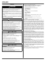
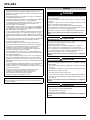
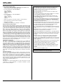
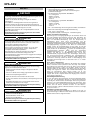
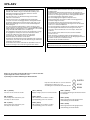
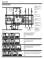
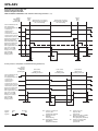
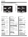
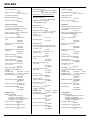
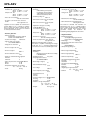
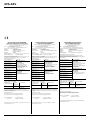
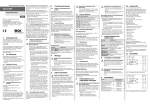
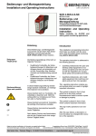
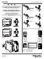
XPS-ABV
www.schneider-electric.com
FR
EN
DE
Module de surveillance pour circuits d'ARRET D'URGENCE
et Applications Verrouillage de Protecteur selon
EN / IEC 60204-1, EN ISO / ISO 13849-1, EN ISO / ISO 13850
(Traduction de l’instruction de service originale)
Safety Relay for monitoring EMERGENCY STOP circuits
and Protective Guard Applications according to
EN / IEC 60204-1, EN ISO / ISO 13849-1, EN ISO / ISO 13850
XPS-ABV....P
(Translation of the original instruction sheet)
Überwachungsbaustein für Not-Halt Kreise
und Schutztür-Anwendungen gemäß
EN / IEC 60204-1, EN ISO / ISO 13849-1, EN ISO / ISO 13850
(Originalbetriebsanleitung)
35 mm
(1.38 in)
99 mm
(3.89 in)
Encombrements / Dimensions / Maße
XPS-ABV....C
➁
➀
22,5 mm
(0.89 in)
114 mm
(4.48 in)
XPS-ABV....P
35 mm
114 mm
(4.48 in)
XPS-ABV....P
XPS-ABV....C
13 23 24 37
A1 S33 S34 S35
13 23 24 37
A1 S33 S34 S35
(1.38 in)
111 mm
(4.37 in)
Repérage des bornes / Terminal marking / Klemmenanzeiger
22,5 mm
(0.89 in)
XPS-ABV....C
XPSABV
XPSABV
SUPPLY
SUPPLY
K1/
K2
K1/
K2
K3/
K4
S
S
S21 S22 S31 A2
14 S11 S12 38
24 375
13 233 S34 S3
A1 S3
XPSABV
24 375
13 233 S34 S3
A1 S3
XPSABV
SUPP
K1/
K2
LY
K1/
K2
LY
K3/
K4
1,5
1
2
K3/
K4
2,5
0,5
0,3
0,15
1,5
1
SUPP
24V c
Note / Note / Hinweis:
Temporisation de retombée (K3, K4)
réglables /
Off-delay time (K3, K4) adjustable /
Rückfallverzögerungszeit (K3, K4)
einstellbar,
XPSABV1133• :
XPSABV11330• :
0,3
0,15
2,5
3
S
3
24V c
S
A2
2 S31
S21 S21 S12 38
14 S1
A2
2 S31
S21 S21 S12 38
14 S1
XPS-ABV....P
BBV61412.00
12 - 04 - 2010
1 / 12
S21 S22 S31 A2
14 S11 S12 38
0,15 … 3 s
1,5 … 30 s
2
0,5
XPS-ABV....C
K3/
K4
Vue de face / Front View / Frontansicht
SUPPLY
LED verte / green / grün
K1,K2
LED verte / green / grün
K3, K4
LED verte / green / grün
XPS-ABV
FRANÇAIS
DANGER
TENSION DANGEREUSE
Le montage, la mise en service, les modifications et le rééquipement ne
doivent être effectués que par un électrotechnicien ! Débranchez
l’appareil / le système avant de commencer les travaux !
Dans le cas d’une défaillance de l’installation ou du système, les
appareils du circuit de commande sans isolation électrique peuvent être
sous tension réseau !
Lors de l’installation des appareils, respectez les réglementations de
sécurité pour usage électrique et de la caisse de prévoyance contre les
accidents.
L’ouverture du boîtier ou toute autre manipulation entraîne l’expiration
de la garantie.
Le non-respect de cette directive entraînera la mort, des blessures
graves ou des dommages matériels.
ATTENTION
UTILISATION INAPPROPRIÉE
En cas d'usage non approprié ou d'utilisation non conforme, l'appareil
ne peut plus être utilisé et nous refusons tout recours à la garantie.
Des actions non autorisées peuvent être:
forte charge mécanique de l'appareil, qui survient par ex. lorsqu'il
tombe, ainsi que tensions, courants, températures et humidité en
dehors des limites définies dans les spécifications.
Lors de la première mise en service de la machine/de l'installation,
veuillez contrôler toujours toutes les fonctions de sécurité
conformément aux prescriptions en vigueur et respecter les cycles de
contrôle prescrits pour les dispositifs de sécurité.
Le non-respect de cette directive peut entraîner des lésions
corporelles et/ou des dommages matériels.
ATTENTION
DANGER Á L´INSTALLATION
Respectez le mesures de sécurité suivantes avant
l’installation / le montage ou le démontage :
1. Débranchez l’appareil / le système avant de commencer les travaux !
2. Protégez la machine / le système contre les redémarrages
intempestifs !
3. Assurez-vous que la machine est hors tension !
4. Reliez les phases à la terre et court-circuitezles !
5. Couvrez et isolez les pièces voisines sous tension !
6. Le montage des appareils doit être effectué dans une armoire
électrique avec une classe de protection min. IP 54.
Le non-respect de cette directive peut entraîner des lésions
corporelles et/ou des dommages matériels.
ATTENTION
PROTECTION PARTIELLE CONTRE LES CONTACTS
ACCIDENTELS
• Classe de protection selon EN/IEC 60529.
• Boîtier / bornes : IP 40 / IP 20.
Module de surveillance pour circuits d'ARRET D'URGENCE et
Applications Verrouillage de Protecteur
• Module de surveillance conformément à EN / IEC 60204-1 et
EN ISO / ISO 13850 pour le contrôle de l’arrêt d’urgence et
Applications Verrouillage de Protecteur.
• Pour catégorie d’arrêt 0 selon EN / IEC 60204-1:
- PL e / Catégorie 4
- MTTFd = 53 Années
- PFHd > 3 x 10⁻⁸ 1/h
- SILCL 3
• Pour catégorie d’arrêt 1 selon EN / IEC 60204-1:
- PL e / Catégorie 3
- MTTFd = 53 Années
- PFHd = 2 x 10⁻⁷ 1/h
- SILCL 2
• Contrôle monocanal ou à deux canaux par contacts ou semiconducteur appropriée.
• Boucle de retour pour le contrôle des contacteurs externes
• Détection de courts-circuits
• 3 contacts de sécurité (2 NO instantanés, 1 NO temporisé à la
retombée)
Description de l´appareil a Description fonctionelle
Après mise sous tension du module, arrêt d'urgence déverrouillé, une
impulsion sur le BP de validation déclenche le cycle d'auto-contrôle et de
mise en route. Les relais internes K1 à K4 montent et s'auto-maintiennent
par leurs contacts auxiliaires. Les contacts de sécurités sont alors fermés
(bornes 13/14, 23/24 et 37/38). 3 LEDs signalent l'état 2 canaux de
sécurité K1/K2 et K3/K4, et la présence tension. Si l'arrêt d'urgence est
actionné (ouverture des contacts du BP), l'alimentation des relais
internes K1 et K2 est coupée. Les deux contacts de sécurité instantanés
s'ouvrent immédiatement (temps de retombée tR1) et le contact de
sécurité temporisé reste fermé. Après écoulement de la temporisation
paramétrée (tR2), K3 et K4 retombent et le contact 37/38 s'ouvre. La
temporisation de retombée est réglable. Un câblage approprié en deux
canaux (BP d'AU ou IDP capot) permet de détecter les défauts de
courts-circuits et de mise à la masse. Le relais de sécurité est protégé
par un fusible électronique. Après disparition du défaut, le module est
prêt à fonctionner après environ 3 s.
Surveillance du poussoir de validation
Le module permet de contrôler un éventuel dysfonctionnement (collage,
masse) du BP de validation. Le réarmement peut en effet être déclenché
sur un front descendant du BP (borne S34) ou sur un front montant
(borne S35). En mode réarmement manuel, le BP de validation doit être
câblé entre S33/S34. Le réarmement est alors déclenché sur le front
descendant. Ceci permet de contrôler une fermeture puis une ouverture
du BP (contrôle dynamique du BP). Pour les applications de contrôle de
capot mobile, le réarmement automatique du module est souvent requis.
Un shunt entre S33/S35 est alors nécessaire. Le module se réarme si le
circuit est fermé (connexion interne réalisée entre S33 et S12 pour
obtenir un front montant).
Contrôle de désynchronisme
Sur certaines installations ou machines, le contrôle des capots mobiles
est réalisé par deux IDP (zones dangereuses à accès fréquent). Le
module de sécurité est alors câblé en deux canaux. Dans ce cas, le
module permet de contrôler ou non le temps de désynchronisme entre la
fermeture des canaux. Si le canal 1 (S11/S12) se ferme avant le canal 2
(S21/S22), le désynchronisme maxi. autorisé est tS ≈0,5 s. Si le canal 2
se ferme avant le canal 1, il n'y a plus de contrôle de désynchronisme
tS = ∞ . Attention: le contrôle du désynchronisme augmente la sécurité du
système et rend la fraude plus difficile.
Usage conforme
Les appareils sont des relais de sécurité. Ils doivent uniquement être
utilisés comme composants de dispositifs de protection sur les machines,
en vue de protéger l'homme, le matériel et la machine.
• Protection des doigts selon EN 50274.
Le non-respect de cette directive peut entraîner des lésions
corporelles et/ou des dommages matériels.
2 / 12
XPS-ABV
Note:
• Le niveau de performance et la catégorie de sécurité selon la norme
EN ISO / ISO 13849-1 dépendent du câblage extérieur, du cas
d’application, du choix de l’émetteur d’ordres et de l’agencement sur
la machine sur place.
• L’utilisateur doit effectuer une évaluation du risque conformément à
la norme EN ISO / ISO 14121-1.
• Il convient de réaliser sur cette base une validation de l’ensemble de
l’installation / de la machine selon les normes applicables.
• Le module contient des relais électromécaniques. Par conséquent
sa valeur MTTFd dépend de la charge et de la fréquence de
manoeuvre dans le cas d’utilisation.
La valeur MTTFd en année mentionnée ci-dessus a été déterminé
en admettant une valeur B10d pour charge maximale de 400.000 et
un nombre moyen de manoeuvres nop = 8760 cycles / an ( cf. EN
ISO / ISO 13849-1, C.2.4 et Tab. K.1).
• Le niveau de performance indiqué est uniquement garantit, tant que
le nombre de manoeuvres et les charges mentionnés ne sont pas
dépassés. Après atteinte de ces limites, l'appareil doit être remplacé,
cependant au plus tard après une durée d'utilisation maximale de 20
ans.
• Lorsque la charge électrique est connue, le diagramme de durée de
vie électrique (voir pages 9/12) doit être utilisé pour calculer le
nombre de manœuvres maximum.
• L’utilisation de l’appareil non conforme aux spécifications peut
provoquer des dysfonctionnements ou la destruction de l’appareil.
• En principe, lors de l’utilisation de l’appareil, les temps indiqués
doivent être respectés, leur non-respect pouvant mener au
verrouillage de l’appareil. Le verrouillage peut être supprimé par
l’ouverture correcte des entrées de sécurité.
• Pour la duplication des contacts de sortie, il est possible d’utiliser
des blocs d’extension ou des contacteurs-disjoncteurs externes avec
des contacts à guidage forcé.
ENGLISH
DANGER
HAZARDOUS VOLTAGE
Only trained professional electricians may install, startup, modify, and
retrofit this equipment!
Disconnect the device / system from all power sources prior to starting
any work!
If installation or system errors occur, line voltage may be present at the
control circuit in devices without DC isolation!
Observe all electrical safety regulations issued by the appropriate
technical authorities or the trade association. The safety function can be
lost if the device is not used for the intended purpose.
Opening the housing or any other manipulation will void the warranty.
Failure to follow this instruction will result in death or serious
injury.
CAUTION
UNINTENDEND USE
If the device has been subjected to improper or incorrect use it must no
longer be used, and the guarantee loses its validity.
Impermissible conditions include:
strong mechanical stress, for example through a fall, or voltages,
currents, temperatures or humidity outside of the specifications.
Before starting up your machine/plant for the first time, please be sure
to check all the safety functions according to valid regulations, and
observe the specified test cycles for safety equipment.
Failure to follow this instruction can result in injury or equipment
damage.
• Les appareils sont dotés d’une protection contre les surcharges (en
cas de court-circuit) Après l’élimination de la cause de la panne,
l’appareil est de nouveau prêt à fonctionner après env. 3 secondes.
• Avant d’activer le poussoir de start, la chaîne de l’arrêt d’urgence doit
être fermée.
• La sortie S11/S33 est uniquement destinée au raccord d'émetteurs
d'ordre conformément au mode d'emploi, et non au raccord de
récepteurs externes, comme par exemple des lampes, relais ou des
contacteurs-disjoncteurs.
CAUTION
RISKS ON INSTALLATION
Perform the following precautionary steps prior to installation, assembly,
or disassembly:
1. Disconnect supply voltage to the equipment / system prior to starting
any work!
• Lors de la connexion de commutateurs magnétiques avec les
contacts reed ou de détecteurs avec les sorties de semiconducteurs, faire attention au courant de pointe (voir
Caractéristiques techniques Circuit de contrôle).
2. Lockout/tag the equipment / system to prevent accidental activation!
• Respecter le schéma des installations notes.
5. Protect against adjacent live components using guards and barriers!
3. Confirm that no voltage is present!
4. Ground the phases and short to ground!
6. The devices must be installed in a cabinet with a protection class of
at least IP 54.
Note:
Observez également les informations de votre caisse de prévoyance
contre les accidents !
Failure to follow this instruction can result in injury or equipment
damage.
CAUTION
LIMITED CONTACT PROTECTION
• Protection type according to EN/IEC 60529.
• Housing/terminals: IP 40 / IP 20.
• Finger-proof acc. to EN 50274.
Failure to follow this instruction can result in injury or equipment
damage.
3 / 12
XPS-ABV
Safety Relay for monitoring EMERGENCY STOP circuits and
Protective Guard Applications
• Safety Relay to EN / IEC 60204-1 and EN ISO / ISO 13850 E-stop
monitoring and Protective Guard Applications.
• For stop category 0 acc. EN / IEC 60204-1:
- PL e / Category 4
- MTTFd = 53 Years
- PFHd > 3 x 10⁻⁸ 1/h
- SILCL 3
• For stop category 1 acc. EN / IEC 60204-1:
- PL e / Category 3
- MTTFd = 53 Years
- PFHd = 2 x 10⁻⁷ 1/h
- SILCL 2
• Single or twochannel control with contacts or semiconductors
• Cross monitoring, synchronous time monitoring
• Start button monitoring
• 3 enabling current paths (2 non delayed, 1 off-delayed)
Device and Function Description
With the supply voltage applied to terminals A1/A2 and the E-Stop circuit
closed, the control logic is activated by closing the contact of the START
button. This last controls the K1 to K4 relays that after the response time
tA1 become self-locking. After this switch-on phase the three safety paths
at the output 13/14, 23/24 and 37/38 are closed. Three LEDs display the
status of the K1/K2, K3/K4 internal relays and the power supply. If the
E-Stop contact switch is opened the current leads for the K1 and K2
relays are interrupted. The enabling current paths 13/14, 23/24 at the
output are immediately opened (after their release time tR1) and the
off-delayed contact 37/38 stays closed during the preset off-delay time
tR2. The off-delay time can be adjusted. With a two-channel con-nection
of the E-Stop switch and cross monitoring wiring of the E-Stop circuit, it is
possible to monitor the presence of a short circuit between the connected
cables (cross monitoring) and ground faults. An internal electronic circuit
protects the device relay from damages. After eliminating the fault the
item will return into operation after about 3 s.
START button monitoring
The device is equipped with the monitoring feature for the START key.
The device can be enabled with the falling edge (START released) or
rising edge (START closed) of the signal (terminals S34 or S35). For the
specific use in the emergency stop applications with manual START the
START button must be connected to terminals S33/S34. The device is
enabled only with a falling edge of the START signal. In order to start the
START button has to be closed and released. For those applications with
protective gates where an automatic START must be performed, it is
necessary to jumper terminals S35 with S35. The device will react at the
rising edge of the input signal at S12 which is internally connected to
S33.
Synchronous check
The use of safety limit switches for single or dual channel circuit in the
protective gate application depends from the required safety level. The
device features a dual channel control and in addition a synchronous
check of the limt switches on request. Precondition for a simultaneity
check tS ≈0,5 s is the position of the limit switches. The limit switches
must be positioned so that channel 1 (terminals S11/S12) has to close
before channel 2 (terminals S21/S22) does. If channel 2 closes before
channel 1 the synchronous time tS = ∞ .
Note:
• The performance level and safety category in accordance with
EN ISO / ISO 13849-1 depends on the external wiring, the
application case, the choice of control station and how this is
physically arranged on the machine.
• The user must carry out a risk assessment in accordance with
EN ISO / ISO 14121-1.
• The entire system/machine must undergo validation in accordance
with the applicable standards on the basis of this.
• The module contains electro-mechanical relays. Therefore his
indicated MTTFd value depend on the load and on the operating
cycles in the application.
The above mentioned MTTFd values in years has been determined
with a supposed B10d-value for maximal load of 400.000 and an
average switching quantity nop = 8760 cycles / year ( cp. EN ISO /
ISO 13849-1, C.2.4 and Tab. K.1).
• The specified performance level can only be assured, as long as the
mentioned number of switching cycles and loads are not exceeded.
The device must be replaced on reaching this maximum figure.
Thereby at the latest after a service life of 20 years.
• If the current load is known, use the diagram for the electrical service
life (see page 9/12) to calculate the maximum number of switching
cycles.
• Operating the device not within the specifications may lead to
malfunctions or the destruction of the device.
• Operate the START button not longer than 3 s. The indicated times
must be observed when the device is operated, otherwise the device
could lock. Locking can be cancelled by opening the safety inputs
properly.
• Expansion devices or external contactors with positively driven
contacts can be used to duplicate the enabling current paths.
• The devices are equipped with overload protection (for short-circuit).
After the malfunction has been dealt with, the device is operational
again in approx. 3 s.
• Control outputs S11/S13 is exclusively for connecting control devices
as defined in the operating instructions and not for connecting
external consumers such as lamps, relays or contactors.
• Close the E-Stop circuit before operate the START button.
• If sensors with reed contacts or semiconductor outputs used pay
attention to the peak current (see technical data section control
circuits).
• Please consult the installation notes.
Note:
Please observe instructions from safety authorities.
Proper Use
The devices are safety switching devices. They must only be used as
components of safety equipment on machines intended to protect
persons, material and plant.
4 / 12
XPS-ABV
DEUTSCH
GEFAHR
GEFÄHRLICHE SPANNUNG
Die Montage, Inbetriebnahme, Änderung und Nachrüstung darf nur von
einer Elektrofachkraft ausgeführt werden!
Schalten Sie das Gerät/ die Anlage vor Beginn der Arbeiten
spannungsfrei!
Bei Installations und Anlagenfehlern kann bei nicht galvanisch
getrennten Geräten auf dem Steuerkreis Netzpotential anliegen!
Beachten Sie für die Installation der Geräte die Sicherheitsvorschriften
der Elektrotechnik und der Berufsgenossenschaft.
Überwachungsbaustein für Not-Halt und Schutztüranwendungen
• Überwachungsbaustein nach EN / IEC 60204-1
und EN ISO / ISO 13850 für Not-Halt - Überwachung und
Schutztüranwendungen
• Für Stop-Kategorie 0 gemäß EN / IEC 60204-1:
- PL e / Kategorie 4
- MTTFd = 53 Jahre
- PFHd > 3 x 10⁻⁸ 1/h
- SILCL 3
• Für Stop-Kategorie 1 gemäß EN / IEC 60204-1:
- PL e / Kategorie 3
- MTTFd = 53 Jahre
- PFHd = 2 x 10⁻⁷ 1/h
- SILCL 2
• Ein- oder zweikanaliges Ansteuerung durch Kontakte oder Halbleiter
Durch Öffnen des Gehäuses oder sonstige Manipulation erlischt
jegliche Gewährleistung.
• Querschlusserkennung, Gleichzeitigkeitsüberwachung
Die Nichtbeachtung dieser Anweisung wird Tod oder schwere
Körperverletzung zur Folge haben.
• 3 Freigabestrompfade (2 unverzögerte, 1 rückfallverzögerter)
VORSICHT
UNSACHGEMÄSSER GEBRAUCH
Bei unsachgemäßen Gebrauch oder nicht bestimmungsgemäßer
Verwendung darf das Gerät nicht mehr verwendet werden und es
erlischt jeglicher Gewährleistungsanspruch.
Nicht zulässige Einwirkungen können sein:
starke mechanische Belastung des Gerätes, wie sie z.B. beim
Herunterfallen auftritt, Spannungen, Ströme, Temperaturen,
Feuchtigkeit außerhalb der Spezifikation.
Bitte überprüfen Sie gemäß der geltenden Vorschriften bei
Erstinbetriebnahme Ihrer Maschine/ Anlage immer alle
Sicherheitsfunktionen und beachten Sie die vorgegebenen Prüfzyklen
für Sicherheitseinrichtungen.
Die Nichtbeachtung dieser Anweisung kann Körperverletzung
oder Materialschäden zur Folge haben.
VORSICHT
GEFAHR BEI INSTALLATION
Führen Sie vor Beginn der Installation/ Montage oder Demontage
folgende Sicherheitsmaßnahmen durch:
1. Schalten Sie das Gerät/ die Anlage vor Beginn der Arbeiten
spannungsfrei!
2. Sichern Sie die Maschine/ Anlage gegen Wiedereinschalten!
3. Stellen Sie die Spannungsfreiheit fest!
4. Erden Sie die Phasen und schließen Sie diese kurz!
5. Decken und schranken Sie benachbarte, unter Spannung stehende
Teile ab!
6. Der Einbau der Geräte muss in einem Schaltschrank mit einer
Schutzart von mindestens IP 54 erfolgen.
Die Nichtbeachtung dieser Anweisung kann Körperverletzung
oder Materialschäden zur Folge haben.
VORSICHT
EINGESCHRÄNKTER BERÜHRUNGSSCHUTZ
• Schutzart nach EN/IEC 60529.
• Start - Taster - Überwachung
Geräte- und Funktionsbeschreibung
Nach Anlegen der Versorgungsspannung an die Klemmen A1/A2 und
bei nicht betätigtem Not-Halt-Taster wird mit dem Start-Taster die
Kontroll-Logik erregt. Diese steuert die Relais K1 bis K4 an, die (bei
Start mit Start-Taster-Überwachung nach der Ansprechzeit) in
Selbsthaltung gehen. Nach dieser Einschaltphase sind die
3 Freigabestrompfade geschlossen (Klemmen 13/14, 23/24 und 37/38).
Die Anzeige erfolgt durch 3 LEDs, die den Relais K1/K2, K3/K4 und der
Versorgungsspannung zugeordnet sind. Wird der Not-Halt-Taster
betätigt, werden die Stromzuführungen für die Relais K1 und K2
unterbrochen. Die unverzögerten Freigabestrompfade (Klemmen 13/14,
23/24) werden mit der Rückfallzeit tR1 geöffnet, der rückfallverzögerte
Freigagestrompfad (Klemmen 37/38) nach der eingestellten
Rückfallverzögerungszeit tR2. Die Rückfallverzögerungszeit kann
stufenlos von 0,15 bis 3 s (XPSABV1133•) bzw. 1,5 bis 30 s
(XPSABV11330•) eingestellt werden. Bei zweikanaliger Ansteuerung
und querschlusserkennender Verdrahtung des Signalgeberkreises
werden zusätzlich Fehler, wie Quer- oder Masseschluss erkannt. Eine
elektronische Sicherung schützt das Gerät vor Beschädigung. Nach
Beseitigung der Störungsursache ist das Gerät nach ca. 3 s wieder
betriebsbereit.
Start - Taster - Überwachung
Zum Starten des Gerätes kann wahlweise die fallende oder steigende
Flanke verwendet werden (Klemmen S34 oder S35). Für Not-HaltAnwendungen mit manuellem Start muss der Taster an die Klemmen
S33/S34 angeschlossen werden. Die Freigabe erfolgt nur mit der
fallenden Flanke des Start-Signals. Zum Starten muss die Start-Taste
betätigt und losgelassen werden. Für Schutztür-Anwendungen, bei
denen ein automatischer Start realisiert werden soll, ist eine
Drahtbrücke zwischen den Klemmen S33/S35 notwendig. Das Gerät
reagiert dann auf die steigende Flanke des Eingangs S12, da dieser
intern mit S33 verbunden ist.
Gleichzeitigkeitsüberwachung
Je nach gefordertem Sicherheitsniveau bei der Schutztür-Anwendung,
ist ein ein- oder zweikanaliger Einsatz von Sicherheits-Grenztastern
notwendig. Das Gerät bietet bei zweikanaliger Ansteuerung außerdem
wahlweise eine Gleichzeitigkeitsüberwachung der Grenztaster. Eine
Synchronzeit tS ≈0,5 s setzt voraus, dass die Grenztaster so angeordnet
werden, dass der Kanal 1, Klemmen S11/S12, vor dem Kanal 2,
Klemmen S21/S22, schließt. Schließt der Kanal 2 vor Kanal 1, so beträgt
die Synchronzeit tS = ∞ .
Bestimmungsgemäße Verwendung
Die Geräte sind Sicherheits-Schaltgeräte. Sie dürfen nur als Teil von
Schutzeinrichtungen an Maschinen zum Zweck des Personen-, Materialund Maschinenschutzes eingesetzt werden.
• Gehäuse/Klemmen: IP 40 / IP 20.
• Fingersicher nach EN 50274.
Die Nichtbeachtung dieser Anweisung kann Körperverletzung
oder Materialschäden zur Folge haben.
5 / 12
XPS-ABV
Hinweis:
• Der Performance-Level sowie die Sicherheits-Kategorie nach
EN ISO / ISO 13849-1 hängt von der Außenbeschaltung, dem
Einsatzfall, der Wahl der Befehlsgeber und deren örtlicher
Anordnung an der Maschine ab.
• Der Anwender muss eine Risikobeurteilung nach EN ISO /
ISO 14121-1 durchführen.
• Auf dieser Basis muss eine Validierung der Gesamtanlage /
-maschine nach den einschlägigen Normen durchgeführt werden.
• Das Modul enthält elektromechanische Relais und somit ist sein
MTTFd Wert abhängig von der Last und der Schalthäufigkeit im
Anwendungsfall.
Der oben angegebnen MTTFd Wert in Jahren wurde mit einem
angenommenen B10d-Wert für maximale Last von 400.000 und der
mittleren Anzahl von Betätigungen nop = 8760 Zyklen / Jahr ermittelt
(vergl. EN ISO / ISO 13849-1, C.2.4 und Tab. K.1).
• Der angegebene Performance-Level ist nur gewährleistet, solange
die angegebenen Schaltspiele und Lasten nicht überschritten
werden. Nach Erreichen dieser Grenzen ist das Gerät
auszutauschen, aber spätestens nach der maximalen
Gebrauchsdauer des Gerätes von 20 Jahren.
• Bei bekannter Strombelastung ist das Diagramm für die elektrische
Lebensdauer (siehe Seite 9/12) für die Berechnung der maximalen
Schaltspiele heranzuziehen.
• Das Betreiben des Gerätes außerhalb der Spezifikation kann zu
Funktionsstörungen oder zur Zerstörung des Gerätes führen.
Hinweis:
• Der Start-Taster darf bei manuellen Start (S34) nicht länger als 3 s
betätigt werden.
Grundsätzlich sind beim Betrieb des Gerätes die angegebenen
Zeiten einzuhalten, ansonsten kann es zur Verriegelung des Gerätes
kommen. Die Verriegelung kann durch ordnungsgemäßes Öffnen
der Sicherheitseingänge aufgehoben werden.
• Zur Vervielfältigung der Freigabestrompfade können
Erweiterungsgeräte oder externe Schütze mit zwangsgeführten
Kontakten eingesetzt werden.
• Die Geräte sind mit einem Überlastschutz (bei Kurzschluss)
ausgerüstet. Nach Beseitigung der Störungsursache ist das Gerät
nach ca. 3 s wieder betriebsbereit.
• Der Steuerausgang S11/S33 dient ausschließlich dem Anschluss
von Befehlsgebern laut Gebrauchsanweisung und nicht dem
Anschluss externer Verbraucher, wie z.B. Lampen, Relais oder
Schützen.
• Bevor der Start-Taster aktiviert wird, muss die Not-Halt-Kette
geschlossen sein.
• Beim Anschluss von Magnetschaltern mit Reedkontakten oder
Sensoren mit Halbleiter-Ausgängen muss der Eingangsspitzenstrom
beachtet werden (siehe Technische Daten).
• Beachten Sie die Installationshinweise.
Hinweis:
Bitte beachten Sie auch die Informationen Ihrer Berufsgenossenschaft!
Diagnostic du système à l'aide des DEL dans le couvercle du boîtier
System diagnostics LEDs on the front cover
Systemdiagnose mittels LED-Anzeige im Gehäusedeckel
1
SUPPLY
2
K1/K2
3
K3/K4
Disposition des DEL dans le couvercle du boîtier
Arrangement of LEDs in the cover
Anordnung der Leuchtdioden im Gehäusedeckel
DEL 1: (SUPPLY)
LED 1: (SUPPLY)
LED 1: (SUPPLY)
Présence tension aux bornes A1/A2.
Supply voltage is present on terminals A1/A2.
Versorgungsspannung an den Klemmen A1/A2
ist vorhanden.
DEL 2: (K1/K2)
LED 2: (K1/K2)
LED 2 indique l’état d’excitation (autoentretien) des deux canaux.
LED 2 indicates the excitation condition
(self-maintaining) of the two channels.
DEL 3: (K3/K4)
LED 3: (K3/K4)
LED 3 indique l’état d’excitation (autoentretien) des deux canaux.
LED 3 indicates the excitation condition
(self-maintaining) of the two channels.
LED 2: (K1/K2)
LED 2 signalisiert den Erregungszustand
(Selbsthaltung) der beiden Kanäle.
LED 3: (K3/K4)
LED 3 signalisiert den Erregungszustand
(Selbsthaltung) der beiden Kanäle.
6 / 12
XPS-ABV
Schéma de câblage de XPS-ABV
Wiring diagram for XPS-ABV
Anschlußplan für XPS-ABV
S1=
Bouton poussoir d'ARRET
D'URGENCE doté de 2 contacs
à ouverture
EMERGENCY STOP - push
button with two NC contacts
Not-Halt - Taster mit zwei
Öffnerkontakten
+24V
F0
Boucle de retour
(contacteurs extérieurs)
(1)
(2)
Feedback circuit
(external contators)
S2
Rückführkreis
(externe Schütze)
F1
(3)
F2
(3)
F3
(3)
S2 =
Bouton marche
Start Button
Starttaste
ESC
A1
S33
S34
XPS-ABV
S35
RESET
CONTROL LOGIC
+
-
Supply
CH1
CH2
CH2
+
-
+
S12
S21 S11
23
37
K1
K4
S22 S31
14
24
38
S1
Catégorie d’arrêt 0
Stop Category 0
Stop-Kategorie 0
0V
ESC =
Conditions de démarrage
externes
External start conditions
Externe Startbedingungen
(1) =
Avec surveillance du bouton de
démarrage
With monitoring of the start
button
Mit Starttasterüberwachung
K2
K3
Time [s]
A2
13
Catégorie d’arrêt 1
Stop Category 1
Stop-Kategorie 1
Sorties de sécurité
Safety outputs
Sicherheitsausgänge
(2) =
Sans surveillance du bouton de
démarrage ou démarrage
automatique
Without start button monitoring
or automatic start.
Ohne Starttaster überwachung
oder automatischem Start.
(3) =
Voir caractéristiques techniques
pour le calibre
maximal des fusibles.
See Technical Data for
maximum fuse sizes.
Siehe technische Daten für
max. Sicherung.
Installation 1 … 4
1
1.1
1
Arrêt d’urgence 1 canal avec démarrage manuel
Emergency Stop, single channel with manual start
Not-Halt, einkanalig mit manuellem Start
1.1 Start (avec surveillance du poussoir S34)
Start (with start button monitoring S34)
Start (mit Start-Taster-Überwachung S34)
1.2 Shunt
Jumper
Brücke
1.2
Start
S11
2
S12 S31
S33
S34
S21 S22
2.1
S1
2
Arrêt d’urgence 2 canaux détection de courts-circuits avec démarrage manuel
Emergency Stop, two channel with manual start without cross monitoring
Not-Halt, zweikanalig mit manuellem Start und ohne Querschlusserkennung
2.1 Start (avec surveillance du poussoir S34)
Start (with start button monitoring S34)
Start (mit Start-Taster-Überwachung S34)
2.2 Shunt
Jumper
Brücke
2.2
Start
S11
S12 S31
S33
3
S34
S21 S22
3.1
3
3.2
Start
S11
4
S12 S21 S22
S1
S11
S12
S33
S2
S21
S22
S34
S11 S31
4.1
S33
4.2
S35
S11 S31
Arrêt d’urgence 2 canaux détection de courts-circuits avec démarrage manuel
Emergency Stop, two channel with manual start and cross monitoring
Not-Halt, zweikanalig mit manuellem Start und Querschlusserkennung
3.1 Start (avec surveillance du poussoir S34)
Start (with start button monitoring S34)
Start (mit Start-Taster-Überwachung S34)
3.2 Shunt
Jumper
Brücke
4
Porte de protection détection de courts-circuits avec démarrage automatique
Safety Guard, two channel with automatic start and cross monitoring
Schutztür, zweikanalig mit automatischem Start und Querschlusserkennung
4.1 Shunt ou boucle de retour pour contacteurs extérieurs (démarrage automatique
S35)
Jumper or feedback loop for external contators (automatic start S35)
Brücke oder Rückführkreis für externe Schütze (automatischer Start S35)
4.2 Shunt
Jumper
Brücke
7 / 12
XPS-ABV
Diagramme fonctionel du XPS-ABV
Functional Diagram XPS-ABV
Funktionsdiagramm XPS-ABV
ARRÊT D’URGENCE / EMERGENCY STOP / NOT-HALT-Anwendung (Installation 1, 2, 3)
Départ
Start
Start
Tension
d'alimentation
Supply On
Spannung Ein
Départ
Start
Start
Arrêt d´urgence áctionné
Emergency Stop Activated
Not - Aus betätigt
Arrêt d´urgence non áctionné
Emergency Stop Deactivated
Not - Aus unbetätigt
Tension d’alimentation (A1-A2)
Power Supply (A1-A2)
Versorgungsspannung (A1-A2)
1. Canal S11-S12
1. Channel S11-S12
1. Kanal S11-S12
2. Canal S21-S22, (S11-S31)
2. Channel S21-S22, (S11-S31)
2. Kanal S21-S22, (S11-S31)
Départ front descendant S33-S34
Start falling edge S33-S34
Start fallende Flanke S33-S34
Départ front montant S33-S35
Start rising edge S33-S35
Start steigende Flanke S33-S35
Sortie 13-14, 23-24 (NO)
Output 13-14, 23-24 (NO)
Ausgang 13-14, 23-24 (S)
Sortie 37-38 (NO)
Output 37-38 (NO)
Ausgang 37-38 (S)
tW
>tM
>tM
tA
tV
tE1
>tA
tE1
Porte de protection / Safety Guard / Schutztür-Anwendung (Installation 4)
Tension
d'alimentation
Supply On
Spannung Ein
Porte fermée
Guard closed
Schutztür geschlossen
Porte ouverte
Guard open
Schutztür geöffnet
Porte fermée
Guard closed
Schutztür geschlossen
Tension d’alimentation (A1-A2)
Power Supply (A1-A2 )
Versorgungsspannung (A1-A2)
1. Canal S11-S12
1. Channel S11-S12
1. Kanal S11-S12
2. Canal S21-S22, (S11-S31)
2. Channel S21-S22, (S11-S31)
2. Kanal S21-S22, (S11-S31)
Départ front montant S33-S35
Start rising edge S33-S35
Start steigende Flanke S33-S35
Sortie 13-14, 23-24 (NO)
Output 13-14, 23-24 (NO)
Ausgang 13-14, 23-24 (S)
Sortie 37-38 (NO)
Output 37-38 (NO)
Ausgang 37-38 (S)
tE2
tA
tV
Légende
Legend
Legende
Activé
On
Ein
Désactivé
Off
Aus
tW
tS
tA
tE2
tW = Temps de réarmement
Recovery time
Wiederbereitschaftszeit
tA =
Temps de réponse
Response time
Ansprechzeit
tE =
tV =
Temps de rétombée (réglable)
OFF delay (adjustable)
Verzögerungszeit (einstellbar)
tS =
Temps de synchronisation
Synchronisation time
Synchronzeit
Délai de fermeture
ON delay
Einschaltverzug
tM = Durée mini de maintien
Min. ON time
Mindesteinschaltdauer
8 / 12
XPS-ABV
Durée de vie électrique des contacts de sortie selon EN/IEC 60947-5-1 / Annexe C.3
Electrical life of the output contacts determined by EN/IEC 60947-5-1 / Annex C.3
Elektrische Lebensdauer der Ausgangskontakte gemäß EN/IEC 60947-5-1 / Anhang C.3
Contact 13-14, 23-24
Contact 13-14, 23-24
Kontakt 13-14, 23-24
Contact 37-38
Contact 37-38
Kontakt 37-38
100
Courant de commutation x 0,1 A
Nominal Operating Current x 0.1 A
Schaltstrom x 0,1 A
Courant de commutation x 0,1 A
Nominal Operating Current x 0.1 A
Schaltstrom x 0,1 A
100
AC-1: 230V
DC-1: 24V
AC-15: 230V
10
DC-13: 24V
1
10 4
10 5
AC-1: 230V
AC15: 230V
10
1
10 5
10 6
Cycles de manoeuvre
Operation Cycles
Schaltspiele
TECHNICAL DATA
- Année de fabrication:
- Year of manufacturing:
-Données sur les bornes et les connexions
10 6
10 7
Cycles de manoeuvre
Operation Cycles
Schaltspiele
CARACTERISTIQUES TECHNIQUES
2010
DC13: 24V
TECHNISCHE DATEN
2010
- Baujahr:
2010
- Klemmen- und Anschlussdaten
-Terminals and connection
XPS-ABV....P
XPS-ABV....P
XPS-ABV....P
Connection un fil
Single wire connection
Einzelleiteranschluß
Sans embout:
rigide
flexible
0,2-2,5 mm2
0,2-2,5 mm2
Ohne Aderendhülse:
starr
flexibel
0,2-2,5 mm2
0,2-2,5 mm2
Longueur de dénudage:
7 mm
Without cable end:
solid
0.2-2.5 mm2
stranded
0.2-2.5 mm2
AWG 24-12
Abisolierlänge:
7 mm
Stripping length:
Flexible avec embout
(sans colleret plastique):
(avec colleret plastique):
0,25-2,5 mm2
0,25-1,5 mm2
Couple de rotation min.:
0,5 Nm
Connection deux fils
Sans embout:
rigide
flexible
0,2-1 mm2
0,2-1,5 mm2
Longueur de dénudage:
7 mm
Flexible avec embout
(sans colleret plastique):
0,25-1 mm2
Flexible avec embout TWIN
(avec colleret plastique):
0,5-1,5 mm2
Couple de rotation min.:
0,5 Nm
Flexible with cable end
(without plastic sleeve):
0.25-2.5 mm2 (22-14 AWG1))
(with plastic sleeve):
0.25-1.5 mm2 (22-16 AWG1))
Tightening torque, min.:
0,5 Nm (4.4 lb-in)
Multiple-wire connection (2 wires max.)
Without cable end:
solid
0.2-1 mm2 (24-18 AWG1))
stranded
0.2-1.5 mm2 (24-16 AWG1))
Stripping length:
7 mm (0.28 in.)
Flexible with cable end
(without plastic sleeve):
0.25-1 mm2 (22-18 AWG1))
Flexible with TWIN-cable end
(with plastic sleeve):
0.5-1.5 mm2 (20-16 AWG1))
XPS-ABV....C
Connection un fil
Tightening torque, min.:
Sans embout:
rigide
flexible
0,2-2,5 mm2
0,2-2,5 mm2
Longueur de dénudage:
10 mm
Flexible avec embout
(sans colleret plastique):
(avec colleret plastique):
7 mm (0.28 in.)
0,25-2,5 mm2
0,25-2,5 mm2
Connection deux fils
Flexible avec embout TWIN
(avec colleret plastique):
0,5-1 mm2
0,5 Nm (4.4 lb-in)
Flexibel mit Aderendhülse
(ohne Kunststoffhülse):
0,25-2,5 mm2
(mit Kunststoffhülse):
0,25-1,5 mm2
Anzugsdrehmoment min.:
0,5 Nm
Mehrleiteranschluß (2 Leiter max.)
Ohne Aderendhülse:
starr
flexibel
0,2-1 mm2
0,2-1,5 mm2
Abisolierlänge:
7 mm
Flexibel mit Aderendhülse
(ohne Kunststoffhülse):
0,25-1 mm2
Flexibel mit TWIN-Aderendhülse
(mit Kunststoffhülse):
0,5-1,5 mm2
Anzugsdrehmoment min.:
0,5 Nm
XPS-ABV....C
Einzelleiteranschluß
XPS-ABV....C
Ohne Aderendhülse:
starr
flexibel
0,2-2,5 mm2
0,2-2,5 mm2
Single wire connection
Abisolierlänge:
10 mm
Without cable end:
solid
0.2-2.5 mm2
stranded
0.2-2.5 mm2
AWG 24-12
Flexibel mit Aderendhülse
(ohne Kunststoffhülse):
0,25-2,5 mm2
(mit Kunststoffhülse):
0,25-2,5 mm2
Stripping length:
Mehrleiteranschluß (2 Leiter max.)
10 mm (0.39 in.)
Flexibel mit TWIN-Aderendhülse
(mit Kunststoffhülse):
0,5-1 mm2
9 / 12
XPS-ABV
- Circuit d’alimentation
- Tension nominale UN:
24 V c
- Plage de la tension nominale UB:
24 V c +10%/-15%
(voir plaque signalétique)
- Ondulation résiduelle USS:
max. 2,4 V
- Puissance assignée DC:
typ. 2,6 W
- Circuit de commande
- Tension de sortie S11/S33, utilisée
seulement pour alimentation des entrées
S34, S35, S12, S31, S22:
typ. 22 V c
- Temps de réponse / temps de réarmement
fusible (résistance PTC):
typ. 2 s
typ. 3 s
- Courant nominal / Courant de pointe
(S12):
typ. 25 mA /
typ. 50 mA
- Courant nominal / Courant de pointe
(S31, S22):
typ. 25 mA /
typ. 100 mA
- Courant nominal / Courant de pointe
(S34, S35):
typ. 40 mA /
typ. 50 mA
- Temps de réponse tA1
(avec surveillance du poussoir):
typ. 30 ms
- Temps de réponse tA2
(sans surveillance du poussoir):
typ. 700 ms
- Temps de relâchement tR1 K1, K2
13 - 14, 23 - 24:
typ. 25 ms
- Temps de retombée tR2 K3, K4
(2 plages de temps réglables)
37 - 38,
XPSABV1133• :
0,15 s ±16% … 3 s ±16%
XPSABV11330• :
1,5 s ±16% … 30 s ±16%
- Durée mini de maintain tM S33-S34:
min. 200 ms
max. 3 s
- Durée mini de maintain tM S33-S35:
min. 200 ms
max. ∞
- Temps de réarmement tW démarrage:
max. 500 ms
- Contrôle de simultanéité tS:
min. 100 ms
max. 500 ms
- Circuit de sortie
- Contacts disponibles:
2 NO contacts de sécurité,
instantanés, contacts guidés
1 NO contact de sécurité, temporisé à
la retombée, contact guidés
- Tension nominale commutation Un:
230 V z
- Courant max. permanent In par contact:
6A
- Courant max. total pour tous contacts:
12 A
Flexible with cable end
(without plastic sleeve):
0.25-2.5 mm2 (24-14 AWG1))
(with plastic sleeve):
0.25-2.5 mm2 (24-14 AWG1))
Multiple-wire connection (2 wires max.)
Flexible with TWIN-cable end
(with plastic sleeve):
0.5-1 mm2 (20-18 AWG1))
1) AWG
indication according to
EN/IEC 60947-1 / table 1
- Nennspannung UN:
24 V c
- Betriebsspannungsbereich UB:
24 V c +10%/-15%
(Siehe Typenschild)
- Restwelligkeit USS:
max. 2,4 V
- Bemessungsleistung DC:
typ. 2,6 W
- Steuerkreis
- Power circuit
- Operating voltage UN:
- Versorgungskreis
24 V c
- Operating voltage range UB:
24 V c +10%/-15%
(Refer to device nameplate for supply
voltage)
- Residual ripple USS:
max. 2,4 V
- Rated power DC:
typ. 2,6 W
- Control circuit
- Internal operating voltage S11/S33, used
only for the supply of the inputs S34, S35,
S12, S31, S22:
typ. 22 V c
- Response time / recovery time of use
(PTC resistor):
typ. 2 s
typ. 3 s
- Rated current / Peak current
(S12):
typ. 25 mA /
typ. 50 mA
- Rated current / Peak current
(S31, S22):
typ. 25 mA /
typ. 100 mA
- Rated current / Peak current
(S34, S35):
typ. 40 mA /
typ. 50 mA
- Response time tA1
(with start button monitoring:
typ. 30 ms
- Response time tA2
(without start button monitoring:
typ. 700 ms
- Release time tR1 K1, K2
13 - 14, 23 - 24:
typ. 25 ms
- Off-delay time tR2 K3, K4
(2 ranges, adjustable)
37 - 38,
XPSABV1133• :
0.15 s ±16% … 3 s ±16%
XPSABV11330• :
1.5 s ±16% … 30 s ±16%
- Min. ON-time tM S33-S34:
min. 200 ms
max. 3 s
- Min. ON-time tM S33-S35:
min. 200 ms
max. ∞
- Recovery time tW Start:
max. 500 ms
- Synchronous monitoring time tS:
min. 100 ms
max. 500 ms
- Nennausgangsspannung S11/S33 zur
Versorgung der Eingänge S34, S35,
S12,S31,S22:
typ. 22 V c
- Ansprechzeit / Wiederbereitschaftszeit
Sicherung (PTC-Widerstand):
typ. 2 s
typ. 3 s
- Nennstrom / Spitzenstrom
(S12):
typ. 25 mA /
typ. 50 mA
- Nennstrom / Spitzenstrom
(S31, S22):
typ. 25 mA /
typ. 100 mA
- Nennstrom / Spitzenstrom
(S34, S35):
typ. 40 mA /
typ. 50 mA
- Ansprechzeit tA1
(mit Start-Taster-Überwachung):
typ. 30 ms
- Ansprechzeit tA2
(ohne Start-Taster-Überwachung):
typ. 700 ms
- Rückfallzeit tR1 K1, K2
13 - 14, 23 - 24:
typ. 25 ms
- Rückfallzeit tR2 K3, K4
(2 Einstellbereiche stufenlos einstellbar)
37 - 38,
XPSABV1133• :
0,15 s ±16% … 3 s ±16%
XPSABV11330• :
1,5 s ±16% … 30 s ±16%
- Mindesteinschaltdauer tM S33-S34:
min. 200 ms
max. 3 s
- Mindesteinschaltdauer tM S33-S35:
min. 200 ms
max. ∞
- Wiederbereitschaftszeit tW Start:
max. 500 ms
- Synchronzeit tS:
min. 100 ms
max. 500 ms
- Ausgangskreis
- Kontaktbestückung:
2 Freigabestrompfade unverzögert,
Schließer, zwangsgeführt
1 Freigabestrompfad rückfallzögert,
Schließer, zwangsgeführt
- Schaltnennspannung Un:
230 V z
- max. Dauerstrom In pro Strompfad:
6A
- max. Summenstrom aller Strompfade:
12 A
10 / 12
XPS-ABV
- Catégorie d’utilisation selon EN/IEC 60947-5-1,
instantané 13 - 14, 23 - 24:
AC15: Ue 230 V a, Ie 4 A
DC13: Ue 24 V c, Ie 3 A
temporisé 37 - 38:
AC15: Ue 230 V a, Ie 3 A
DC13: Ue 24 V c, Ie 3 A
- Durée de vie mécanique:
10 x 106 commutations
- Protection court-circuit max. cartouche
fusible:
classe gG max. 6 A
L'appareil est aussi capable de commuter des
charges faibles (17 V c / 10 mA), à condition
que le contact n'ait jamais commuté de forte
charge auparavant, car la couche d'or revêtant
le contact pourrait être altérée.
- Données générales
- Fixation du boîtier:
Encliquetage sur profilé chapeau
35 mm selon EN/IEC 60715
- Position de montage:
indifférente
- Ligne de fuite entre circuits:
selon EN/IEC 60664-1
- Catégorie de surtension:
III
- Tension assignée de choc:
4 kV
- Tension assignée:
300 V a
- Tension alternative d’essai:
2 kV
- Output circuits
- Contacts:
2 NO enabling current paths,
non-delayed, positively driven
1 NO enabling current paths,
off-delayed, positively driven
- Switching voltage Un:
- Max. total current for all current paths:
12 A
- Application category according
to EN/IEC 60947-5-1,
non-delayed 13 - 14, 23 - 24:
AC15: Ue 230 V a, Ie 4 A
DC13: Ue 24 V c, Ie 3 A
delayed 37 - 38:
AC15: Ue 230 V a, Ie 3 A
DC13: Ue 24 V c, Ie 3 A
- Mechanical service life:
10 x 106 switching operations
- Short-circuit protection, fuse element:
type gG max. 6 A
- Kurzschlußschutz, Sicherungseinsatz:
Klasse gG max. 6 A
Das Gerät ist ebenfalls zum Schalten von
Kleinstlasten (min. 17 V c / 10 mA) geeignet.
Dies ist jedoch nur dann möglich, wenn bisher
über diesen Kontakt keine höheren Lasten
geschaltet
wurden,
da
hierdurch
die
Kontaktvergoldung abgebrannt sein könnte.
- Allgemeine Daten
- Gehäusebefestigung:
Schnappbefestigung auf 35 mm
Normschiene nach EN/IEC 60715
- Einbaulage:
beliebig
- Luft- und Kriechstrecken zwischen den
Stromkreisen:
EN/IEC 60664-1
- General data
- Bemessungsstoßspannung:
4 kV
- Überspannungskategorie:
III
- Mounting:
Mounting on 35 mm DIN rail according
to EN/IEC 60715
- Degré de contamination de l’appareil:
l’intérieur
2
l’extérieur
3
- Classe de protection selon EN/IEC 60529:
Boîtier
IP 40
Bornes
IP 20
- Overvoltage category:
- Poids:
- Mechanische Lebensdauer:
10 x 106 Schaltungen
Minimum switching ratings of outputs:
The device is capable of switching low voltage
loads (min. 17 V c / 10 mA) provided that the
contact has never been used with higher loads.
- Mounting position:
- Température ambiante / de stockage:
-25 … +55 / -25 … +85 °C
230 V z
- Max. rated current In per current path:
6A
- Gebrauchskategorie nach EN/IEC 60947-5-1,
unverzögert 13 - 14, 23 - 24:
AC15: Ue 230 V a, Ie 4 A
DC13: Ue 24 V c, Ie 3 A
verzögert 37 - 38:
AC15: Ue 230 V a, Ie 3 A
DC13: Ue 24 V c, Ie 3 A
Any plane
- Creepage and clearance:
acc. EN/IEC 60664-1
III
- Test voltage:
2 kV
- Verschmutzungsgrad des Gerätes:
innerhalb
2
außerhalb
3
- Schutzart nach EN/IEC 60529:
Gehäuse
IP 40
Klemmen
IP 20
300 V a
- Umgebungs-/Lagertemperatur:
-25 … +55 / -25 … +85 °C
- Power-frequency test voltage:
2 kV
- Contamination level:
internal
external
300 V a
- Prüfwechselspannung:
4 kV
- Rated withstand voltage:
0,2 kg
- Bemessungsspannung:
- Gewicht:
0,2 kg
2
3
- Protection degree acc. to EN/IEC 60529:
Housing
IP 40
Terminals
IP 20
- Ambient / storage temperature:
-25 … +55 / -25 … +85 °C
(-13 … +131°F / -13 … +185°F)
- Weight:
0,2 kg (7 oz)
11 / 12
XPS-ABV
DÉCLARATION CE DE CONFORMITÉ
POUR LES COMPOSANTS DE SÉCURITÉ
EC DECLARATION OF CONFORMITY
FOR SAFETY COMPONENTS
EG-KONFORMITÄTSERKLÄRUNG
FÜR SICHERHEITSBAUTEILE
(Traduction française de la Déclaration CE de Conformité d'origine
Référence du document : BBV6141000.00)
(English translation of the original EC declaration of conformity,
Document-no.: BBV6141000.00)
(Kopie der original EG-Konformitätserklärung,
Dokument-Nr.: BBV6141000.00)
Nous:
Schneider Electric Industries SAS
35, rue Joseph Monier / 92506 Rueil Malmaison, France
WE:
Schneider Electric Industries SAS
35, rue Joseph Monier / 92506 Rueil Malmaison, France
WIR:
Schneider Electric Industries SAS
35, rue Joseph Monier / 92506 Rueil Malmaison, France
Déclarons que le composant de sécurité
hereby declare that the safety component
erklären hiermit, daß das nachstehend aufgeführte Sicherheitsbauteil
MARQUE:
SCHNEIDER ELECTRIC
TRADEMARK:
SCHNEIDER ELECTRIC
MARKE:
NOM, TYPE:
Module de surveillance pour circuits
D'ARRÊT D'URGENCE
PRODUCT, TYPE:
Safety Relay for monitoring EMERGENCY STOP
circuits
NAME, TYP:
Überwachungsbaustein für Not-Halt Kreise
MODELL:
XPS-ABV
MODELES:
XPS-ABV
MODELS:
XPS-ABV
SERIENNUMMER:
siehe original EG-Konformitätserklärung
NUMÉRO DE SÉRIE:
voir de la Déclaration CE de Conformité d’origne
SERIAL NUMBER:
refer to original EC declaration of conformity
FERTIGUNGSDATUM: siehe Typenschild
DATE DE FABRICATION:
voir plaque signalétique
DATE OF MANUFACTURING:
refer to device nameplate
est conforme à l'ensemble des recommandations en matière de protection
stipulées dans les consignes suivantes.
Une description de la Déclaration avec les normes européennes
harmonisées est fournie ci-après.:
all the essential protection requirements that are described in the following
directives are defined, corresponding.
Furthermore, the conformity with the following harmonized European
standards explained:
DATE DE RÉFÉRENCE:
DIRECTIVE:
DATED REFERENCE:
DIRECTIVE:
EN 60947-01:2007
(DIN EN 60947-01:2008-04)
DIRECTIVE 2004/108/CE
DU PARLEMENT EUROPÉEN
ET DU CONSEIL
du 15 décembre 2004
relative au rapprochement des
législations des États membres
concernant la compatibilité
électromagnétique et abrogeant la
directive 89/336/CEE
EN 60947-01:2007
(DIN EN 60947-01:2008-04)
DIRECTIVE 2004/108/EC OF THE
EUROPEAN PARLIAMENT
AND OF THE COUNCIL
of 15 December 2004
on the approximation of the laws of the
Member States relating to
electromagnetic compatibility and
repealing Directive 89/336/EEC
DIRECTIVE 2006/42/CE
DU PARLEMENT EUROPÉEN
ET DU CONSEIL
du 17 mai 2006
relative aux machines et modifiant la
directive 95/16/CE (refonte)
EN 60204-01:2006
(DIN EN 60204-01:2007-06)
EN 61000-6-02:2005
(DIN EN 61000-6-2:2006-03)
EN 61000-6-04:2001
(DIN EN 61000-6-4:2002-08)
EN 60947-5-01:1997 + A12:1999
+ A1:1999 + A2:2000
(DIN EN 60947-5-01:2000-08)
EN 60204-01:2006
(DIN EN 60204-01:2007-06)
EN 62061:2005
(DIN EN 62061:2005-10)
EN ISO 12100-2:2003
(DIN EN ISO 12100-2:2004-04)
EN 61000-6-02:2005
(DIN EN 61000-6-2:2006-03)
EN 61000-6-04:2001
(DIN EN 61000-6-4:2002-08)
EN 60947-5-01:1997 + A12:1999
+ A1:1999 + A2:2000
(DIN EN 60947-5-01:2000-08)
DIRECTIVE 2006/42/EC OF THE
EUROPEAN PARLIAMENT
AND OF THE COUNCIL
of 17 May 2006
on machinery, and amending
Directive 95/16/EC (recast)
EN 62061:2005
(DIN EN 62061:2005-10)
EN ISO 12100-2:2003
(DIN EN ISO 12100-2:2004-04)
allen wesentlichen Schutzanforderungen, die in den nachfolgenden
bezeichneten Richtlinien festgelegt sind, entspricht.
Weiterhin wird die Konformität mit folgenden harmonisierten Europäischen
Normen erklärt:
DATIERTE FUNDSTELLE:
RICHTLINIENBEZUG:
EN 60947-01:2007
(DIN EN 60947-01:2008-04)
RICHTLINIE 2004/108/EG DES
EUROPÄISCHEN PARLAMENTS
UND DES RATES
vom 15. Dezember 2004
zur Angleichung der Rechtsvorschriften
der Mitgliedstaaten über die
elektromagnetische Verträglichkeit und
zur Aufhebung der
Richtlinie 89/336/EWG
EN 61000-6-02:2005
(DIN EN 61000-6-2:2006-03)
EN 61000-6-04:2001
(DIN EN 61000-6-4:2002-08)
EN 60947-5-01:1997 + A12:1999
+ A1:1999 + A2:2000
(DIN EN 60947-5-01:2000-08)
EN 60204-01:2006
(DIN EN 60204-01:2007-06)
EN ISO 13849-1:2008
(DIN EN ISO 13849-01:2008-12)
EN ISO 13849-2:2003
(DIN EN ISO 13849-02:2003-12)
EN ISO 13849-2:2003
(DIN EN ISO 13849-02:2003-12)
L'organisme agréé suivant a établi une déclaration positive selon le
Chapitre 7, phrase 2, 2004/108/EG:
The following notified body has made a positive declaration in accordance to
Chapter 7, Sentence 2, 2004/108/EG:
RÉFÉRENCE DE
RÉFÉRENCE
L'ORGANISME AGRÉÉ: DE LA
DÉCLARATION:
NOM, ADRESSE:
NUMBER OF THE
NOTIFIED BODY:
NUMBER OF
DECLARATION:
NAME, ADDRESS:
0340
ET 10064
0340
BG
Gustav-Heinemann-Ufer 130
D-50968 Köln
BG
Gustav-Heinemann-Ufer 130
D-50968 Köln
EN ISO 12100-2:2003
(DIN EN ISO 12100-2:2004-04)
EN ISO 13849-2:2003
(DIN EN ISO 13849-02:2003-12)
Sous réserve d’installation, d’entretien et d’utilisation conformes à sa
destination, à la réglementation, aux normes en vigueur, aux instructions du
constructeur et aux règles de l’art.
It is important that the safety component is subject to correct installation,
maintenance and use conforming to its intended purpose, to the applicable
regulations and standards, to the supplier’s instructions and to accepted rules
of the art.
Documentation autorité:
Eric Léon Barry / Schneider Electric Automation GmbH /
Steinheimer Straße 117 / 63500 Seligenstadt, Germany
Documentation authority:
Eric Léon Barry / Schneider Electric Automation GmbH /
Steinheimer Straße 117 / 63500 Seligenstadt, Germany
France - Rueil Malmaison
15 - Avril - 2010
France - Rueil Malmaison
15 - April - 2010
Folgende benannte Stelle hat eine positive Erklärung im Sinne des
Artikels 7, Satz 2, 2004/108/EG ausgestellt:
KENNNUMMER DER
NUMMER DER
BENANNTEN STELLE: ERKLÄRUNG:
NAME, ANSCHRIFT:
0340
BG
Gustav-Heinemann-Ufer 130
D-50968 Köln
ET 10064
Falls es gemäß seiner Bestimmung, den geltenden Vorschriften, Normen und
Herstelleranweisungen entsprechend installiert, verwendet und gewartet
wird.
Dokumentationsbevollmächtigter:
Eric Léon Barry / Schneider Electric Automation GmbH /
Steinheimer Straße 117 / 63500 Seligenstadt, Germany
Frankreich - Rueil Malmaison
15 - April - 2010
p. p. François Mondino
OEM R&D Vice-President
RICHTLINIE 2006/42/EG DES
EUROPÄISCHEN PARLAMENTS
UND DES RATES
vom 17. Mai 2006
über Maschinen und zur Änderung der
Richtlinie 95/16/EG (Neufassung)
EN 62061:2005
(DIN EN 62061:2005-10)
EN ISO 13849-1:2008
(DIN EN ISO 13849-01:2008-12)
EN ISO 13849-1:2008
(DIN EN ISO 13849-01:2008-12)
ET 10064
SCHNEIDER ELECTRIC
i. V. François Mondino
OEM R&D Vice-President
p. p. François Mondino
OEM R&D Vice-President
Die original EG-Konformitätserklärung ist auf unserer Webseite erhältlich:
www.schneider-electric.com
La Déclaration CE de Conformité d'origine est disponible sur notre site Web:
www.schneider-electric.com
The original EC Declaration of Conformity is available on our website:
www.schneider-electric.com
Schneider Electric Industries SAS / 35, rue Joseph Monier / 92506 Rueil-Malmaison, France
12 / 12