1
Vakuumtechnik
VakuumVerfahrenstechnik
Meß-und
Analysentechnik
LEYBOLD
AG
LEYBOLD
E i nU n t e r n e h m edne r D e o u s s a
GA 09.600/3
Gebrauchsanweisung
Operating Instructions
M o d ed ' e m p l o i
sM 42,SV 110
Membran-Druckschalter.
Schaltverstärker
Pressure
Diaphragm
Switch,Switching
Amplifier
Pressostat
ä membrane,
amplificateur
de commutation
1 6 40 5 / 0 6 / 0 7 8 r . 2 . 1 6 07 8
ACHTUNC !
Vor ieder lnanspruchnahme des Services ist es aus
Gründen der Arbeitssicherhett und des Umweftschutzes notwendig, am oder im Gerät betindliche, gefährliche Sloffe (2.8. im Sinne EG.Richtlinie L360, 1976/1979
oder VBG 16) anzuzeigen und zu deklarieren. Solern
keine Deklaration er{olgt, muB davon ausgegangen
werden, daB das Gerät von deradigen Stoften frei ist.
Inhalt
IMPORTANf!
Belore consufting the Service Dept., please declara, tor
the sake of operational safe} end envircnmental
protectian, any toxic or other hazardous products (e.9.
as defined in EEC directive L360, 197611979or VBG 16)
existing in or around the apparatus lo be seviced. ln
the absence ot any such decleration, it wlll be assu'
med that tha apparatus is lree of such substancas.
AIf ENTION !
Pour des raisons li6es ä le söcuritö et ä l'environnement,
priäre d'indiquer ä chaque demande d'intewention du
servjce apräs-venle les produits dangereux (p.ex. eu
lerme des directives de la CE L 300, 1976/1979 ou VBG
16) se trouvanl sur ou dans I'epparell.En I'absenca de
toute indication, on coneidi,reta que I'appareil est
exempt de tels produits
Contents
Sommalre
Beschreibung
1
1.1 AllgemeineAngaben
1.1.1 Venrvendungszweck
3
3
4
1
Descriptlon . . .
1 . 1 General
1 . 1 . 1Puroose
1.2 Technische Daten
1.2,1 Membran-Druckschalter
SM 42
1.2.2 Schaltverstärker
SV 110
4
4
5
4
1.2 Technical Data
1.2.1 DiaphragmPressureSwitchSM 42 4
5
1 . 2 . 2 S V 11 0 S w i t c h r nAg m p l i f i e r
4
1.2 Donnöestechniques . . .
4
1.2.1 Pressostat
ä membrane
SM 42
1.2.2 Amplificateur
SV 110 5
de commutation
1.3 TechnischeBeschreibung
1.3.1 Membran-Druckschalter
SM 42
1.3.2 Schaltverstärker
SV 110
5
5
1.3 Technical Description . . . . . . .
1.3.1 DiaphragmPressureSwitchSM 42
'l.3.2 SV 110 SwitchingAmplifier
5
5
6
5
1.3 Descriptiontechnique . . .
5
1.3.1 Pressostat
ä membraneSM 42
SV 110 6
1.3.2 Amplificateur
de commutation
1.4
1.4.1
1.4.2
7
1.4 Equipement
1.4,1 Equioement
standard
1 . 4 . 2 A c c e s s o i r e.s. .
1 . 4 Ausstattung
1 . 4 . 1Lreferumfang. .
1 . 4 . 2 Zubehör
2
2.1
2.2
Bedienung und Betrieb
Anschlußan dreAooaratur
Anschlußvon
Elektrischer
Membran-Druckschalter
und
Schaltverstärker.
Wanung
b
3
3
4
1
Description
1.1 lndicationsg6n6rales
1.1.1 Application
3
3
4
-l
1
7
7
7
ö
1'l
2
2.1
2.2
7
7
'l
Operation
-7
Connectionto the system
Electricalconnectionof diaphragm
pressureswitchand switching
I
amolifier
Maintenance
11
2
2.1
2.2
7
7
7
7
Utllisation et service
7
Raccordement
au systöme
Raccordement
Ölectrique
du pressostat ä membraneet de l'amplificateur
I
de commutation
Entretien
11
1 Beschrelbung
1.1Allgemeine
Angaben
1 Descriptlon
1.1General
1 Description
1.1 Indlcatlonsg6n6rales
Die Gebrauchsanweisung
enthältwichtigelnformationenzum Verständnis,zur Aufstellung
und Inbetriebnahme.
These Operatinglnstructionscontainimportant
informationon funclion. installationand startu0.
Ce mode d'emploidonne des informationsimportantespour comprendre,installer,mettre en
service,utiliser,rbpareret entretenir.
Vorsicht; steht bei Arbeits-und Betriebsverfahren, die genau einzuhaltensind, um eine
Gefährdungvon Personenauszuschließen.
Caution; indicates proceduresthat must be
strictly observed to prevent hazards to persons.
Prudence; signale des travaux ou opÖrations
ä respecter scrupuleusementpour ne pas
mettredes personnesen danger.
Achtung; beziehtsich auf Arbeits- und Betriebsverfahren,die genau einzuhaltensind,
um Beschädigungenoder Zerstörungendes
Geräteszu vermeiden.
lmportant; indicatesproceduresthat must be
strictly observed to prevent damage or destruction,
Attention; signale des travaux ou oS6rations
ä respecter scrupuleusementafin d'Öviter les
ou destructions.
endommagements
Hinwels; gilt für technischeErfordernisse,
die
der Benutzerbesondersbeachtenmuß.
Note; indicatesspecialtechnicalrequirements
thal the user musl complywith.
Remarque; signaledes contraintestechniques
auxouellesI'utilisateurdevra faire particuliÖre'
ment attention.
Abbildungshinweise
z.B. (212\geben mit der
ersten Zifter die Abbildungsnummer
an und
mit der zweiten Zifter dte Positionin dieser
Abbildung.
The referencesto diagrams,e.g. (2121,
consist
of the Fig. No. and the ltem No. in that order.
Les chiffres entre parenthÖsesdans le texte
comme p.ex. (212)se rapportentpour le premier chitfreau numörode la figure et pour le
deuxiömeau numöroconcern6dans la lögende
de cette frgure.
Lielerung auf Vollständigkeitprufen (siehe
Abschnitt1.4) und einer sorgfältigenSichtprüfungunterzrehen.
Gheck that the suppliedequipmentis complete (see Section 1.4) and check the condivisually.
tion of the instruments
ContrOler si la livraison est complÖte (cf.
section 1.4) et etfectueraussitÖtun contrÖle
visuelapprofondides öqurpements.
Werden Beschädigungen
festgestellt,ist umgehendeine Schadensmeldung
an den Spediteur und den Versichererzu leiten. Falls es
notwendigist, das beschädigteTeil zu ersetzen, bitte mrt der Auftragsabteilung
in Verbindung setzen.
lf any damage is discovered,report il immediatelyto the fonvardingagent and insurer.lf
the damaged part has to be replaced,please
get in touch with the ordersdepartment.
Lorsque des dommagessont constatÖs,il faut
immödiatementen faire dÖclarationä I'expÖditeur et ä I'assureur.Veuillezvous mettreen
contact avec le service commandess'il est nÖcessairede remplacerune piöceendommagöe,
1.1.1 Venvendungszweck
Der Membran-Druckschalter
SM 42 mit dem
SchaltverstärkerSV 110 eignet sich zur
druckabhängigen
Signalgebung,zum Steuern
von Ventilen und Pumoen oder bei Veruvendung von zwei Gerätenzur Intervallregelung.
1.1.1 Purpose
The SM 42 DiaphragmPressureSwitch with
the SV 110 SwitchingAmplifieris suitableas
a source of pressure-dependent
signals for
controllingvalves and vacuum pumps and, if
two are employed,for interualoperation.
lm einzelnensind die technischenDaten im
Abschnitt1.2 zu beachten.
Note the TechnicalDatagtvenin sectiont.2.
1.1.1 Application
Le pressostatä membraneSM 42 avec l'amplificateurde commutationSV 110 est utilis6
pour fournrrun signalölectriqueen fonctionde
la pression,pour commandedes robinetet des
pompes,ainsi que pour röaliserune rögulation
entre une pressionmax. et min. avec appareils
conlug6es.
Notezles donnöestechn.dansla sec. 1.2.
1.2 Technische Daten
1.2 Technical Data
1.2 Donn6esTechniques
1.2.1 Membran-Druckschalter
SM 42
1.2.1 DiaphragmPressureSwitch SM 42
1.2.1 Pressostatä membraneSM 42
Arbeitsbereiche
Normalausführung
mit fest eingestelltem
Schaltdruck*)zwischen
1 bis 6 moar
5 bis 50 mbar
40 bis 400 mbar
Ansprechempfrndlichkeit
10 % des
kleinsteneingestellten
Schaltdruckes
Vakuumanschluß
DN 20 KF
Temp. Koeffizient
5 o/"K'1
ZulässigeUmgebungstemperatur
max.50'C
Meßvolumen
220 cm3
Working ranges
Standardversionwith permanentlyset
1 to 6 mbar
switchingpressure.)between
5 to 50 mbar
40 to 400 mbar
Responsesensitivity
10 o/"ol the lowest
presetswitching
pressure
Vacuumconnection
DN 20 KF
Temperaturecoetficienl
5 o/olK
Permissible
ambienttemoeraturemax.50 'C
Measuringvolume
220 cm3
Zones d'utilisation
Modöle normalavec oressronde
r ö f ö r e n c e f i x ed.e)
1ä6mbar
5 ä 50 mbar
40 ä 400 mbar
Sensibilitöde röponse ögaleä 1Oo/oöe la
pressionde döclenchement
169lable
minimale
Raccordement
DN 20 KF
au vide
Coefficientde temörature
5 oh lK
Temp6ratureambianteadm.
max.50 'C
Steuerkontakt
Max. zulässigerSchaltstrom
10 mA
Max, zulässigeSchaltspannung
24 V
max.
Ubergangswiderstand,
1 kQ
ZulässigeUmgebungstemperatur
max.50 "C
Gewicht
1,4 kg
Control contact
10mA
Max. switchrngcurrent
Max. switchingvoltage
24V
1k8
Max. contactresistance
Permissible
ambienttemperaturemax.50 'C
1.4 kg
Weight
Contact de commande
Courantde commutationmax.adm. 1 0 m A
Tensionde commutationmax.adm.
24V
Rösistancede contactmax.
1ko
TempÖrature
max. 50 oC
ambianteadm.
Poids
1,4 kg
r) gewünschten
S c h a l t d r u c ka n g e b e n
*)
')
4
Pleasestate desired switching pressure
Volume de mesure
220 cm3
Priöre spdcifier pressionde r6firence requise
1,2.2 Schaltverstärker
SV 110
1 . 2 . 2 S V 1 1 0 s w i t c h i n ga m p l i f i e r
1.2.2 Amplificateurde commutation
Netzanschluß
Mainssupply
Tensionsecteur
sv 110
11 0 b i s 1 3 0 V
220 bis 240 V
50/60 Hz
3VA
1 1 0t o 1 3 0V
220 to 240 V
50/60 Hz
3VA
1 1 0ä 1 3 0v
220 ä 240 V
50/60 Hz
3VA
Netärequenz
Leistungsauf
nahme
Ausgangsrelais
Schaltspannung,
max.
250V
Schaltstrom,max.
5A
Schaltleistung,
max.
5OOVA
Ansprechzeit
30 ms
Abschaltzeit
7ms
Steuerkrers
2 4 V 1 1 0m A
Umgebungstemperatur,
max.
50 "c
Gewicht
0,36 kg
Schaltverstärker
K a t . - N r .1 6 0 7 8
SV 110
Mainsfrequency
Powerconsumption
Outputrelay
250 v
Switchingvoltage,max.
Switchrngcurrent,max.
5A
5OOVA
Switchingcapactty,max.
Responsetime
30 ms
7ms
Releasetime
2 4 V 1 1 0m A
Controlcircuit
Ambienttemperature,
firäX.
50 0c
Weight
0.36 kg
SV 110 SwitchingAmplifier Cat.No.160 78
FrÖquence
secteur
Puissanceabsorböe
Relaisde soflie
Tensionde commutation,
max.
250 V
max.
Couranlde commutation,
5A
Pouvoirde coupure,max.
5OOVA
Tempsde röponse
30 ms
7ms
Tempsde coupure
24Vt10mA
Circuitde commande
Tempöratureambiante,env.
50 .c
Poids
0,36 kg
Amolificateur
de commutation
No. de cat. 160 78
SV110
1.3 Technische Beschrelbung
1.3 Technlcal Description
1.3
1.3.1 Membran-Druckschalter
SM 42
Die Schaltdoseenthält eine Membrankapsel,
die au{ einen niedrigenVergleichsdruck
evakuiert ist. Bei Druckmrnderung
im umgebenden Raum biegt sich die Membrane nach
außendurch und schließtbei Erreichendes
eingestellten
SollwerteseinenFeinkontakt.
1.3.1 DiaphragmPressureSwltch SM 42
The metal housing contains a sealed diaphragm capsulewhich is evacuatedto a low
referencepressure.As the pressure in the
vacuum system connected to the pressure
switch falls, the draphragmbulges outwards
and closes a micro-contaclwhen the preset
switchingpressurers reached.
1.3.1 Pressostatä membraneSM 42
fermöe par une
Une capsule hermötiquement
membraneest övacu6eä une oressionröduite
de r6förence.Lorsquela pressionbaisse dans
le systämesous vide, la membranese döforme
vers I'extÖrieur
et ferme un micro-contactdös
que la pressionde röf6renceest attente.
Achtung
Erne Kontaktseiteliegt auf Masse. Deshalb
darf der Membrandruckschalter
nur mit einem
Schaltverstärker
betriebenwerden.
Note
One contact side is connectedto earth. The
diaphragm pressure switch must only be
operated with a switchingampli{ier.
Attention
Un cötö du contact esl ä la terre, C'est
pourquoile pressostatä membranede doit ötre
employö qu'avec un amplificateurde commutalron.
Description
technique
Dre Gasarl und Schwankungendes Atmosphärendruckeshaben keinen Einflußauf die
Schaltgenauigkeit.Die Ansprechempiindlichkeit beträgt 10 16 des kleinsteneingestellten
Schaltdruckes.
The natureof the gas and fluctuationsof the
atmosphericpressure do nol influencethe
switchingaccuracy.The responsesensitivity
rs 10 % of the lowest preset switchingpressure.
La nature du gaz et les variationsde la pression atmosphörique
n'ont pas d'influencesur la
prÖcisionde commutation.La sensibilit6de
räponse est 6gale ä 10 "/" de la pressionde
döclenchement
röglöemin.
1 . 3 . 2 S c h a l t v e r s t ä r k eSr V 1 1 0
1 . 3 . 2 S w i t c h i n gA m p l i f i e r S V 1 1 0
lregt
Der Membrankontakt
der Druckschalter
einseitigauf Masse und ist maximalmtt 24 Vl
10 mA belastbar.
One side of the diaphragmcontact is connectedto earthand it is rated24 V I 10 mA.
1.3.2 Amplificateur de commutatlon SV
110
Le contactä membranedu pressostatest ä la
massepar un cötö.Sa chargemaximaleest 24
v/10m4.
Zu ledem Druckschalterwird deshalb ein
benötrgt.Das mit einem leiSchaltverstärker
WechselkontaktbestuckteAusstungsstarken
gangsrelalsschaltet in Arbeitsstellung,
wenn
der am Druckschalter
eingestellteWert unterschrrttenwird, d. h, wenn sich die Membrandose sowert ausgedehnthat, bis ste den
Gegenkontaktberuhrt. Der Schaltverstarker
SV 110 rst auch zum Betriebder Druckschalt E r P S 1 1 0 A , P S 1 1 1 A , P S 1 1 4 U N dP S
115 geergnet.
Der eingebaute
Schrebeschalter
(3/1)muß auf dreangeschlossene
Druckschalwerden.
tertypeetngestellt
Thereforea switchingamplifieris requiredfor
each pressureswitch.The ruggedchangeover
contacto{ the switchingamplifrerrs activated
as soon as the pressure drops below the
presetvalueon the pressureswttch,r.e.when
the diaphragmhas flexed so much that it
touches the oppositecontact.The switching
in
amplifier
SV 100 is alsosuitedfor operatron
wrththe pressureswrtchesPS 110
connection
A , P S 1 1 1A , P S 1 1 4 a n dP S 1 1 5 .T h e b u i l t in sfidingswitch(3/1),however,mustbe set to
the correspondrng
type of pressureswrtch.
C'est pourquoiun amplificateur
de commutation
est nÖcessairepour chaque pressostat.Le
relais de sodie öquipö d'un contact inverseur
puissantcommuteen positionde travail pour
les valeursinförieures
au röglagedu pressostat,
c.ä.d, lorsquela membranetouche le contact
opposö. L'amplificateurde commutationSV
100 peul Ögalement
travailleravec les pressos t a t sP S 1 1 0A , P S 1 1 1A , P S 1 1 4 e t P S 1 1 5 .
Le commutateurcoulissant(3/1) doit ötre röglö
sur le type de pressostatraccordö.
Dre elektrischeInstallationvon Druckschalter
und Schaltverstärker,
Netzanschlußund Anschluß des zu schaltendenVerbrauchers
gemäßAnschlußbild
(Abb.3) herstellen.
Carry out the electricalInstallation
of pressure
switch and switchingamplifreras well as the
marnsconnectron
and the connecttonof the
externalconsumeras shownin Fro.3.
lnstallation
Ölectrique
du pressostatet de I'amplificateur;
effectuerle raccordement
au secteur
et avec le consommateurexternecomme indiquödansla fig.3.
6
1.4 Equipement
1,4 Equipment
l.4Ausstattung
1.4.1 Equipement
standard
1.4.1 Scopeof dellvery
l,4.l Lieferumfang
RÖI.
Pressostat
ä membrane
SM 42
16078
eVouamplific.
de comm.SV 110
Moded'emploi
GA 09.600
Kat.-Nr.
Ref.No.
Membran-Druckschalter
SM 42
SV 110 160 78
oderI und Schaltverstärker
Gebrauchsanweisung
GA 09.600
Diaphragm
Pressure
SwitchSM 42
Amplifier
or / andSwitching
SV 110 16078
1.4.2 Zubehör
183 22
ZentrierringDN 20 KF
183 42
SpannringDN 20 KF
SpannringDN 16 KF, aus
')
200 28 306
Kunststotf
DN 16 KF, aus Teflon,
Zentrierring
20O28 307
mit VITON-O-Ring')
p512Ql25KF') 183 57
Ubergangszentriernng
183 42
SpannringDN 20/25 KF')
')
183 86
Reduzrerstück
DN 25116KF
1.4.2 Accessories
183 22
Centeringring DN 20 KF
183 42
ClampingringDN 20 KF
ClampingringDN 16 KF
made of plastic')
200 28 306
Centeringring DN 16 KF, madeof Teflon,
200 28 307
with VITON O ring')
Adaptercentering
ring DN 20125KF.) 183 57
183 42
Clampingring DN 20125KF 1
')
1 8 38 6
ReducerDN 25/16KF
1.4.2 Accessoires
Baguede centrageDN 20 KF
Baguede serrageDN 20 KF
DN 16 KF,en
Baguede serrage
2
Operation
2.1 Connectionto the system
2
Utllisationet service
2.1 Raccordement
au systÖme
Der Membran-Druckschalter
wird mit elnem
KleinflanschDN 20 KF an die Apparaturangeschlossen.
Zum Anschlußsind die im Abschnitt 1.4.2 aulgeführtenTeile erforderlich.
ist rn Abb. 1 dargestellt,
Die Maßzeichnung
The DiaphragmSwitchis connectedvia a DN
20 KF small flange to the vacuum system.
This requiresthe partslistedin Section1.4.2.
A dimensional
drawingis givenin Fig. 1.
Le pressostal ä membrane est raccordÖau
systöme par une petite bride DN 20 KF. Les
piöcesindiquöesdans la section1.4.2 sont nÖcessairespour le raccordernent.La fig, 1 fournit le schömacot6.
Den SM 42 senkrecht,
d. h. mit dem Flansch
nach unten, anbnngen.So ist sichergestellt,
daß evtl. Kondensateablaufenkönnen.Dichtelementeund Flanschmussenschmutz-und
fettfreisern.Fur Potentralfreiheit,
muß der SM
42 durch ern lsofierzwischenstuck
von der
Apparaturgetrenntwerden(Abschn.1.4.2).
Mountthe SM 42 vertically,i.e. with its flange
facing downwards.This ensures that any
possibly arising condensateis not trapped.
Sea[ng componentsand flangesmust be free
float the
of any din and grease.To electrrcally
SM 42 an isolatingpiece must be used to
isolatethe SM 42 fuornthe vacuum system.
MonterSM 42 verticalement,
c.ä,d. la brideen
bas pour que les öventuelscondensatspuissent s'6couler. Les 6l6ments d'ötanchÖit6et la
bride doivent ätre exempts de graisse et de
poussiöre.Söparer SM 42 de l'installationpar
une piÖced'rsolementpour assurer I'isolation
(section1.4.2\.
')
')
'l
2
Bedienung und Betrieb
2.1 Anschluß an die Apparatur
Fgr potentiallreie Installalion
Operatinglnstructions
t o r f l o a t i n gi n s l a l l a t i o n
GA 09.600
18322
18342
plastique')
20028 306
Baguede centrageDN 16 KF, en tÖJlon
2OO28 307
avec joint toriqueen VITON')
183 57
Baguede centrageDN 20/25 KF1
183 42
Baguede serrageDN 20125KF 1
1 8 38 6
R ö d u c t e uD
r N 2 5 1 1 6K F ' )
p o u r i n s t a l l s t i o ns a n s p o l e n t i e l
-f-- t
-16.4
['u?
lr
t
I
tt
II
l-
l
s05 ;
I
I
L
A b b . 1 M a ß z e i c h n u n gz u d e n M e m b r a n - D r u c k s c h a l t eSr nM 4 2 l i n k s u n d S c h a l t v e r s l ä r k eSr V 1 1 0 r e c h t s
Fig t D i m e n s i o n e d r a w i n g o f S M 4 2 D i a p h r a g mP r e s s u r eS w i t c h a n d S V 1 1 0 S w i t c h i n gA m p l i l i e r
F i g , 1 C o t e sd e s p r e s s o s t a l sä m e m b r a n eS M 4 2 e t d e l ' a m p l i f i c a t e udr e c o m m u t a t i o nS V 1 1 0
2.2 ElektrischerAnschluß von
Membran-Druckschalter
und
Schaltverstärker
2.2 Electricalconnection of diaphragm pressure switch and
switching amplifier
Vorsicht
Caution
- Uber die Anschlussedes Membran-Druck- - The connectionsof the diaphragmpressure
schaltersdarf auf keinenFall Netzspannung
switch are not designedto withstandmains
geleitetwerden.LEBENSGEFAHR!
voltages,DANGERTO LIFE!
- Das Gehäusepotentialdes Druckschalters - The potentialof the housingof the pressure
gggen Erde darf Schutzkleinspannung
nicht
switch must not exceed the levels for
protectivelow voltages,referredto ground.
überschreiten.
Für den Anschlußdes Membran-Druckschal- To connect the diaphragm pressure switch
proceedas follows:
ters wie tolgtvorgehen:
- Befestigungsschrauben
- Loosenand removethe mountingscrewson
auf der großenKappe des Druckschalters
lösenund abnehmen.
the largecap of the pressureswitch.
- Kappeabziehen,
- Pull otf the cap.
8
2.2 Raccordement tilectrique du
pressostat ä membrane et de
I'amplificateur de commutation
AvertiSsement
- Ne lamais appliquerde tension secteur par
les raccordementsdu pressostatä membrane.DANGERDE MORT!
- Le potentielpar rappon ä la terre du boitier
du pressostatde doil pas döpasserla valeur
des bassestensionsde protection.
Procödercommesuit pour raccorderle pressostat ä membrane:
- Desserreret retirer les vis de fixation du
grandcapuchondu pressostat.
- Retirerle caouchon.
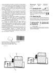
- ZweiadrigeLeitung durch die Leitungstülle
der Kappeziehen.
- Leitungan Masse Pin (21'l)und Signalleitung an Ptn (212)anschließen.
- Lertungenin die Lasche (2/3) einlegenund
(Zugentlastung).
ernquetschen
- Kappe schließenund {estschrauben.
- Pull a two-corecablethroughthe openingof
the caD.
- Connect groundconduclorof the cable to
ptn (2t1) and signalconductorlo pin (212).
- Secure the cable in slrain relief (2/3) and
fastenthe strainrelief.
- Closethe cap and screwit tight.
- Passerun cäbleä deuxconducteursoar l'ouverturedu caouchon.
- Raccorderle cäble ä la massesur la broche
(211)el le cäblesignalsur la broche(212).
- Poser les cäblesdans la patte(2/3) et serrer
(protectioncontreles tractions).
- Fermerle couvercle.
(Abb. 3) befindetsich im
Das Anschlußbild
Deckeldes Schaltverstärkers
SV 110.
The connectrondiagram(Fig. 3) is locatedin
the lid of the SwitchingAmplifierSV 110.
Der Schaltverstärker
ist bei Auslieferungaul
220 bzw. 240 V,50/60 Hz geschaltet.
As suppliedthe SwitchingAmplifieris set to
220 or 240 V,50/60 Hz operation.
Le diagrammede connexion(fig. 3) se trouve
de commusur le couverclede I'amolificateur
t a t r o nS V t t 0 .
L'amplificateur
est commutÖä
de commutatron
la livraisonsur 220 ou 240 V, 50/60 Hz.
Hinweis
Für den Netzanschlußist die Vorschriftder
VDE 0100 zu beachten.
Note
When connectingto the mains observe the
VDE 0100 regulations.
Remarque
Respecterla rögle VDE 0100 pour le raccordementau secteur.
A b b . 2 A n s c h l u ß b i l dS M 4 2 b e i a b g e n o m m e n e K
r lappe
F i g 2 C o n n e c t i o nd i a g r a m o f t h e S M 4 2 w i t h t h e c a p
delached
F i g 2 D i a g r a m m ed e c o n n e x i o nd e S M 4 2 , c a p u c h o n
deimonlö
Erläulerungen zur Abb. 2
1 Anschluß Masse
2 Signalleitung
3 L a s c h el ü r Z u g e n t l a s t u n g
Key to Flg. 2
1 G r o u n dc o n n e c t i o n
2 S i g n a lc o n n e c l i o n
3 Strainrelief
L6gende de la fig. 2
1 Connexionde la masse
2 Connexiondu signal
3 Patteanlilraclion
A b b . / F i g .2
9
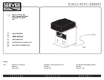
Fur den Anschluß des Schaltverstärkers
SV
110 wie folgtvorgehen:
- Deckeldes Schaltverstärkers
abnehmen.
- Für den Anschlußan Spannungenvon 110
bzw. 130 V. 50/60 Hz die Brücken am
Transformatoranschluß
entsorechend dem
Anschlußbild
Abb, 3 umklemmen.
- De Leitung vom Druckschalteran die
Kontakte"4" und "8" anklemmen.
- Schiebeschalter(3/1) auf den angeschlossenenDruckschaltertyp
einstellen.
- Anschlüsse des a) schaltendenVerbrauchersherausführen.
- Deckelschließen,
L e i t u n g s q u e r s c h n i t t m a x .1 m m 2
L e i t u n g s v e r s c h r a u b uP
n gG 9
LeitungsaußenDurchmesser
4 , 5 b i s6 m m
Cable cross section
Cable connection
Cable diameter
( o u t s i d ed i a . )
Sectiondu cäble
Connexiondu cäble
Diamötreexterne
du cäble
A b b . /F i g .3
10
m a x .1 m m 2
PG9
For connectionof the SwitchingAmplifierSV
110 proceedas follows:
- Removethe lid of the switchrngamplifier.
- For connectionto 110 or 130 V, 50/60 Hz
mains the links on the transformerhave to
be rewired accordino to the connection
diagramof Fig,3.
- Connectthe cable from the pressureswilch
to contacts"4" and "8".
- Set the positiono1 the slidingswitch(3/1) to
the type of pressureswitchused.
- Lead out the connectionsfor the external
consumer.
- Closethe lid,
Procödercommesuit oour le raccordement
de
I'amplificateur
SV 110:
de commutation
- Retirerle couverclede I'amplificateur.
- Positionnerles cavaliersdu raccordement
du
transformateur
commedans le diagrammede
connexionde la fig, 3 pour raccorderdes
tensionsde 110 ou 130 V, 50/60Hz.
- Connecterle cäble du oressostatau contacts
DArtetDB".
- Röglerle commutateurcoulissant(3/1) sur le
type de pressostatraccordö.
- Sortir les connexions du consommateur
externe.
- Fermerle couvercle.
A b b . 3 A n s c h l u B b i l dS c h a l t v e r s t ä r k eSr V 1 1 0
Fig 3 Connectiondiagram of the switching amplifier
Fig 3 Diagramme de connexion de l'amplificateur de
c o m m u l a l i o nS V 1 1 0
SM 42
P S 1 1 0A / 11 1 4
PS114
PS115
Erläuterungen zur Abb. 3
1 Schiebeschaller lür den angeschlossenen Druckschaltertyp
2 Signalleitung(vomDruckschalter)
4.5to 6 mm
Key lo Fig. 3
1 Slide switch for selecting the type ol connected
pressureswitch
2 S i g n a lc o n n e c l i o n( f r o m t h e p r e s s u r es w i t c h )
max. 1 mm2
PG I
4.5 ä 6 mm
11 0 . . , 1 3V0
L6gende de la tig. 3
1 Commutateur glissant pour le type de pressoslal
raccordd
2 Cäble signal (du pressoslat)
3
Wartung
3
Malntenance
3
Entretien
Unter sauberenBetrrebsbedingungen
ist der
Membran-Druckschalter
wartungsfrei.
Under clean conditionsthe diaphragmpressure switchdoes not requireany maintenance.
Pas d'entretrensi les conditionsde travail du
pressostatä membranesont propres.
Das Kontaktpaarkommt mit dem Meßmedium
in Berührung. Ber evtl. auttretendenVerschmutzungenkönnen Schaltfehlerauftreten.
Reinigungund Reparatursind nur im Werk
mög[ch.
The pair of contacts does come into contact
with the medium. ln case of possiblecontamlnationswitchingerrorsmay occur.Cleanrngand repatris only possiblein the factory.
La paire de contacts entre en contact avec le
fluide. Des erreurs de commutationoeuvent
avorrlieu en cas d'encrassage.
Le nettoyageet
la röparationne sonl possiblequ'en usine.
Allgemeine Hinweise
Eine Anderung der Konstruktionund der
Datenbehaltenwir uns vor. Die
angegebenen
Abbildungen
srndunverbindlich.
General Note
The right of alteratronsin the designand the
technrcaldata rs reserved.The illustrattons
are
not brndrno.
Remarque gen6rales
Nous nous röservonsle drort de modifierla
constructtonet les lndicatronsdonnÖes.Les
figuressont sans engagement.
r\
t,
11
or_m
Y
=E
t5 or
sO
Wir stehen
zuIhrerVerfugun
ö
ä
o
o
AG ' KÖLN
Bonner Straße 498 . Postfach 51 0760 . D-5000 Köln 51
Telefon (02 21) 3 47 0 . Telex B BB 481 - 20 lh d Draht leybold köln
Telefax (O2 21\ 3 47 - 12 50
LEYBoLD
@
o
f
f
o
LEYBOLD
LEYBOLD AG . HANAU
Wilhelm-Rohn-Straße25 . Postfach 15 55 . D - 6450 Hanau 1 . Te efon (0 61 81) 34'0
T e l e x4 1 5 2 0 6 - 0 l h d . D r a h t l e v b o l dh a n a u . T e l e f a x( 0 6 1 8 1 ) 3 4 - 1 6 9 0
T
Niederlassungen:
Tochtergesellschaft en :
1'
VERTRIEBSBEREICH NORD
Belgien
Niederlassung Hamburg
Spaldingstraße 1 B
2000 Hamburg 1
Tel.: (0 40) 231676 .Telex 2162261
LEYBOLD N,V
Leuvensesteenweg 641
B - 1930 Zaventem
T e l . : 7 5 9 7 9 3 6 . T e l e x :2 3 8 5 6
Telefax: 7594190
a
g)
o
s(o
@
9)
o
g
o
{
o,
?
g
(rl
o
o
o
I
xq
f
('l
Wittestraße 30 E
1000 Beriin 27
Te . : (0 30) 4 32 50 28 . Telex: 183 811
Telefax: (0 30) 4 32 40 03
Niederlassung Hannover
Eckenerstraße5 A
3000 Hannover 1 Vahrenheide)
T e l . : ( 0 5 1 1) 6 3 2 0 9 9 T e l e x :I 2 3 3 3 1
VERTBIEBSBEREICH
MITTE
Niederlassung Frankf urt
Edisonstraße7
6000 Frankfurt/ M. 60
Tel : (O61 09) 39 02 Teiex: 4 185 967
=
vERTRIEBSBEREIcH sÜDwEsT
t\)
lY
Vo lmoellerstraße11
7000 Stuttgart B0
Tel.: (07 11) 7 35 20 01 . Telex: 7 255 517
G)
5
!
Niederlassung Karlsruhe
I
?
{
o
o
p
x
o
N)
t\)
-i
no)
is
:'!
ol
o-J
Niederlassung Stuttgart
Vorbergstraße5
7500 Karlsruhe 41
T e l .: ( 0 72 1) 4 9 1 9 2 2
('l
do
'Tl
g^+
x
P@
ü@
=@
=
Ä
oö
gr
x t\)
io
6r
€o-
Dänemark
LEYBOLD ApS
Roskildevej342 A
DK - 2630 Tästrup
T e l . :0 2 - € 9 6 4 4 4 . I e l e i a x . 0 2 - S 9 6 5 4 4
England . lrland
TEYBOLD LTD.
Waterside Way Plough Lane
London SW177AB
Tel.:019479744 . Telex: 896 430
T e l e f a x : 0 1 94 7 0 2 1 0
Finnland
LEYBOLD OY
O l a r i n l u o m a1 0
02200 Espoo 20
Iel-. 90 - 42 39 44
Ielefax.422862
Telex: 124 2iB
Frankreich
LEYBOLD S,A,
Z Avenue du Ouebec
Z.A. de Coudab€uf
B . P .1 2 . 9 1 9 4 2 L e s U l i s C e d e x
T e l . :( 1 )6 9 0 7 6 4 0 0 . T e l e x : 6 0 0 8 5 2
Telefax: 1-69075738
VERTRIEBSBEREIcH sÜD
Niederlassung München
Hongkong
Lerchenstraße5
80OO Munchen 50
T e l .: ( 0 8 9 ) 3 5 1 4 0 6 6 / 6 9 . T e l e x : 5 2 1 5 0 6 1
LEYBOLD tTD,
20th Floor . 80 Gloucester Road
Hongkong
T e l . : 5 - 2 0 2 8 8 0 . T e l e x :6 6 7 3 7 l h h k h x
Telefax: 5-8656883
Niederlassung Nürnberg
Endterstraße3
8 5 0 0 N ü r n b e r g4 0
Tel.: (09 11) 4 46 64 40
VERTRIEBSBEREICH
ö6-
Berlin (West)
-.{
o
o
o
-lu
Zweigniederlassung
Italien
WEST
Niederlassung Köln
Wingedsheide 2
5060 Bergisch Gladbach 1
Tel.: (0 22 04) 6 00 67
Niederlassung Bochum
Josef-Baumann-Straße 21
4630 Bochum 1
T e l . :( 0 2 3 4 ) B 5 5 4 5 / 6 / 7 - T e l e x :8 2 5 4 9 7
Technisches Büro Jülich
Grabenstraße 70
5162 Niederzier2
T e l . :( 0 2 4 2 8 ) I 0 7 - 0 . T e l e t e x : 24 2 8 4 0 1 L H S
Telefax: (0 24 28) B 07 11
(
Kanada
LEYBOLD INC.
100 Strada Drive, Unit 4
Woodbridge, Ontario, L4L 5V7
Tel.: (416)851-7327 . Telex: 065-27400
Telefax: (416)851- /950
Niederlande
LEYBOLD B,V
Postfach 90 3440 AB Woerden
Rosmolenlaan 1 . 3447 GL Woerden
T e l . :0 3 4 8 O - 7 7 4 1 1. T e l e x :4 7 6 5 2 l h w d n l
Telefax: 0 34 B0 - 2 04 89
Norwegen
LEYBOLD A/S
Solheimveien 11 . 1473 Skarer
lbl.: 2 97 05 20
Österreich
I-EYBOLD GES.IM,B,H,
Favoritenstraße35 .A 1040 Wien
l e l . : 6 5 1 6 4 4 1 4 5 ' T e l e x : 1 3 14 0 0
Telefax: 505164420
Schweden
L E Y B O L DA B
Box 135
D a t a v ä g e n5 7 I
S-42 122 Västra Frölunda
Telelon:031-684200
T e l e f a x :0 3 1- 6 8 3 9 3 9
Schweiz.
Liechtenstein
TEYBOLD AG
Leutschenbachstraße55 . 8050 Zürich
Tel.: (01) 3 02 36 36 - Telex 823 212
T e l e f a x :( 0 1 ) 3 0 2 4 3 7 3
Spanien
T E Y B O L DS . A ,
CalleBalmes 148-150 . Barcelona
Tel.:218O121/2180.185Telex: 98954 lh e
Telefax: 2379626
USA
LEYBOLD INC.
1 8 6 0 H a r t o g D r v e r S i r n . J o l r ( '( l A 1 ) 5 1 : l l
T e l . (: 4 0 8 ) 4 3 6 2 1 ] : ' l l I | [ r l ; t r , 1 { ] r r ' l : i { i : ' i 1 . 1 ( l
LEYEOLD S,p.A.
Via P Toselli, 11
20127 l,Allano
Tel,: (02) 2 87 15 21 Telex: 330 348
felefax: 2-2871521
T E Y B O L D V A C U U I , 4t ) t { O t ) ti ( r l r i r . J .(
5 7 0 0 M e l l o n F o a d . E x p o r t , F ) a .1 1 ' { ; l J : '
T e l . : ( 4 1 2 j3 2 7 - 5 7 O O . T e l e x r1 9 9 1 3 8
IeleIax . 412 - 7 331217
Japan
LEYBOLD INFICON
6 5 0 0 F l y R o a d . E a s t S y r a c u s e ,N . Y 1 3 0 5 7
Tel.: 315 - 43 41 100 . Telex: 710 541 - 0594
Telefax: 315-4373803
LEYBOLD CO. tTD.
S o g o K u d a n - m i n a m iB u i l d i n g7 - 6 ,
K u d a n - m i n a m r2 - c h o m e
C h i y o d a - k u. T o k y o 1 0 2
Iel. : 3-222-1711 . Telefax: 3-222- 1717
LEYBOLD CON/PONENTS CO.
Service Center
3 - 100, Kashiwai-cho
Kasugai-shi,Aichi-ken, 486
Tel.: 0568-84-8131 . Telefax: 0568-84-1444
LEYBOLD VACUUIV SYSTEMS INC,
'120
Post Road . Enfield, Connecticut 06082
T e l . : 7 4 1 - 2 28 1 . T e l e x :9 5 5 3 4 4
felefax 203-7457932
LEYBOLD TECHNOLOGIES INC.
120, Post Foad . Enfield,CT 06082
T e l : ( 2 0 3 )7 4 1- 2 2 6 7 . T e l e x : 9 5 5 3 4 4
Telefax 203-7457932