1
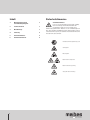
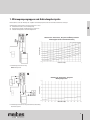
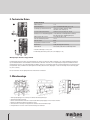
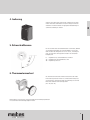
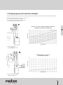
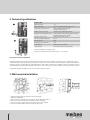
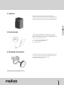
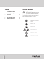
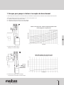
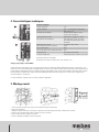
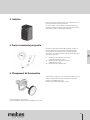
Technische Änderungen vorbehalten
PR 24002.146 08-03-2013
Wärmepumpengruppe
Technische Information für Montage und Betrieb
Heat pump group
Technical information for installation and operation
Groupes pour pompe à chaleur
Documentation technique pour le montage et la mise en service
Meibes System-Technik GmbH
Ringstraße 18 · D-04827 Gerichshain · Tel. + 49(0) 3 42 92 7 13-0 · Fax 7 13-50
Internet: www.meibes.de · E-Mail: [email protected]
DE
GB
FR
Inhalt
Sicherheitshinweise
1.Wärmepumpengruppen
und Anbindungsbeispiele
2
2.
3
Technische Daten
3.Wandmontage
3
4.Isolierung
4
5.Schwerkraftbremse
4
6.Thermometerwecksel
4
Sicherheitshinweise
Lesen Sie vor der Montage diese Anleitung sorgfältig
durch. Die Montage und Erstinbetriebnahme der
Komplettstation darf nur von einer zugelassenen
Fachfirma ausgeführt werden. Machen Sie sich vor Arbeitsbeginn mit
allen Teilen und deren Handhabung vertraut. Bitte befolgen Sie diese
Sicherheitshinweise genau, um Gefahren und Schäden für Menschen
und Sachwerte auszuschließen.
- Vor Gebrauch Monteageanleitung lesen
- Schnittgefahr
- Quetschgefahr
- Gefahr erhöhter Temperatur
- Gefahr elektrischer Spannung
- Sturzgefahr bei der Montage
1
1. Wärmepumpengruppen und Anbindungsbeispiele
Bitte beachten Sie bei der Montage die Vorgaben der Wärmepumpenhersteller für die Mindestumlaufwassermengen.
DE
Wärmepumpen-Verteilerstation für Volumenströme bis 3 m3/h:
�zum direkten Anschluss an die Wärmepumpe
�komplette Ausstattung zur Anbindung eines Heizkreises
�einfache Montage durch Schnellmontagetechnik
1
Volumenstrom - Druckverlust - Diagramm und Öffnungsverhalten
in Abhängigkeit der Überströmventileinstellung
Druckverlust (bar)
Überströmventileinstellung
Volumenstrom (l/h)
1 Einbindungsschema für Heizung
ohne Pufferspeicher
2
Druckverlust (bar)
Volumenstrom - Druckverlust - Diagramm
Wärmepumpenstation
Volumenstrom (l/h)
2 Einbindungsschema für Heizung und Warmwasserbereitung
über Pufferspeicher
2
2. Technische Daten
Technische Daten
Obere Anschlüss:
Untere Anschlüsse:
HE-Pumpe (vgl. aktuelle Preisliste):
1
1”IG
Typ I 1 ½”AG (flachdichtend), Typ II 1“IG
wahlweise Grundfos Alpha 2L 25-60
oder Wilo Yonos PICO 25/1-6
einzusetzender Rücklauffühler:
Durchmesser 6 mm, Länge ca. 45 mm
Anschluss für ein Ausdehnungsgefäß: ¾ AG (Anschluss mit beiligendem T-Stück vgl.
Bild: Montage- bzw. Anbindungsbeispiel)
Abmessungen H/B/T in mm:
ca. H 420 x B 250 x T 246
max. zul. Betriebstemperatur:
110°C
max. zul. Druck:
6 bar
Ansprechdruck Sicherheitsventil:
3 bar
Bauteile aus:
Stahl, Messing, EPP-Isolierung
Dichtmaterial:
PTFE (Teflon) asbestfrei Faserdichtung EPDM
2
1 direkte Einbindung ins Heizsystem
2 Einbindung über Pufferspeicher (mit seitl. Abgängen 1“IG)
Wärmepumpen-Anschluss-Gruppen DN 25
Pumpengruppe komplett mit oder ohne Umwälzpumpe (EL 180 mm) mit Anschlusskabel im Rücklauf; zwei 3-Wege-Kügelhähne (rücklaufseitig mit handaufstellbarer Schwerkraftbremse und Fühlertasche für Fühler D=6 mm; zwei im Kugelhahngriff integrierte Kontaktthermometer
(Anzeigebereich 0-120°C); ein Pumpenkugelhahn mit Meibes-Flansch; im Vorlaufstrang integrierte Sicherheitsbaugruppe mit Sicherheitsventil
(Ansprechdruck 3 bar) und Manometer (Anzeigebereich 0-4 bar); Überströmventil; beigelegtes T-Stück zur Montage eines Ausdehnungsgefäßes; EPP-Isolierung
Bei der Installation sind alle gültigen Normen und Richtlinien einzuhalten.
3. Wandmontage
4
5
1
2
3
1. Wärmepumpengruppe mit Isolierung an vohanden Verrohrung anbringen.
2. Befestigung handfest anziehen.
3. Untere Seiten und Mitte anzeichnen. Anschließend Wärmepumpengruppe mit ISO wieder entfernen.
4. Wand nach Markierung bohren und Dübel einsetzen.
5. Unterschale der Isolierung mit mitgelieferten Schrauben an der Wand befestigen.
6. Kompaktverteiler einsetzen und mit dem Rohrleitungsnetz verbinden.
3
4. Isolierung
DE
Vordere Isolierschale auf die Thermometer schieben und vorsichtig
mit der Hinterschale verbinden! Bei Einsatz in Anlagen zum Heizen
und Kühlen sind interne Bauteile mit geeigneter Kältedämmung vor
Schwitzwasserbildung zu schützen.
5. Schwerkraftbremse
Um eine unerwünschte Schwerkraftzirkulation zu verhindern, befindet
sich im Rücklauf-Kugelhahn eine Schwerkraftbremse. Diese kann
durch Verstellen des Drehgriffes um ca. 45° von der „ Anschlagstellung“ aus nach rechts manuel geöffnet werden. Die Schließkraft
beträgt 0,2 bar.
0° - Kugelhahn offen, Schwerkraftbremse in Funktion
45° - Kugelhahn und Schwerkraftbremse offen
90° - Kugelhahn geschlossen
6. Thermometerwechsel
Das Thermometer kann durch einfaches herausziehen und wieder
hineinstecken gewechselt werden. Es sollte beachtet werden, dass
ein entnommenes Thermometer durch ein gleichartiges ersetzt wird.
Bitte auf die farbliche Kennzeichnung achten.
(Rot = VL, Blau = RL )
Bitte beachten Sie auch unsere weiteren Produkte für den Wärmepumpenbereich.
Die Soleverteiler können beliebig adaptiert werden.
4
Contents
Safety notes
1.
Heat pump group and connection examples
2
2.
Technical specifications
3
3.
Wall-mounted installation
3
4.Isolation
4
5.
Gravity brake
4
6.
Changing thermometer
4
Safety notes
Read through these instructions carefully before installation. The complete station must be installed and
initially started up by an approved, qualified firm.
Familiarise yourself with all the parts and their handling before
starting the work. Please follow these safety instructions closely to
prevent accidents and damage to people and property.
- Read the assembly instructions before
use
- Risk of cuts
- Risk of being crushing
- Risk of increased temperature
- Risk of electrical voltage
- Risk of items falling during installation
5
1. Heat pump group and connection examples
During assembly, please observe the instructions given by the manufacturers of the heat pumps concerning the minimum circulating water quantity.
Heat pump - distribution station for flow rates of max. 3 m3/h:
�For the direct connection to the heat pump
�Complete kit for the connection of a heating circuit
�Easy assembly by quick mounting system
1
pressure loss (bar)
Setting of the overflow valve
Volume flow (l/h)
1 Connection diagram for
heating without buffer tank
2
pressure loss (bar)
Volumetric flow rate – Pressure loss
diagram heat pump station
Volume flow (l/h)
2 Connection diagram for heating
and boiler via buffer tank
6
GB
Flow rate - pressure loss - diagram and opening characteristics
depending on the setting of the overflow valve
2. Technical specifications
Technical Data
Upper connections:
Lower connections:
HE-Pump (cf. current price list):
1
Backflow sensor to be used:
Connection for an expansion vessel:
Dimensions H/B/D in mm:
Max. all operating temperature:
Max. all pressure:
Contact pressure safety valve:
Components of:
sealing material:
2
1”IG
type I 1 1/2”AG (flat sealing), type II 1“IG
optional Grundfos Alpha 2L 25-60
or Wilo Yonos PICO 25/1-6
Diameter 6 mm, length approx 45 mm
¾ AG (connection with enclosed T-piece cf. figure:
assembly and connection example)
approx H 420 x B 250 x D 246
110°C
6 bar
3 bar
Steel, brass, EPP-insulation
PTFE (Teflon) asbestos free fiber EPDM
1 Directly integrated in the heating system
2 Connection via the buffer tank (with outlet pieces 1“ IT on the side)
Heat pump connection groups DN 25
Pump group complete with or without circulation pump (EL 180 mm) with connection cable in the return flow; two 3-way ball valves (return
side with manually set gravity brake and sensor pocket for sensor D=6 mm; two contact thermometers integrated in the ball valve handle (indicated range 0-120°C); one pump ball valve with Meibes flange; safety module with safety valve integrated in the flow line (actuation pressure
3 bar) and manometer (indicated range 0-4 bar); overflow valve; it comes with a T-piece for the assembly of an expansion tank; EPP insulation
All applicable standards and guidelines are to be conformed to during installation.
3. Wall-mounted installation
4
1
2
3
1. Attach heat pump group with insulation to the existing piping.
2. Tighten fixing hand-tight.
3. Draw on the lower sides and centre. Thenremove the heat pump group with ISO.
4. Drill holes in the wall according to the markings and insert rawl plugs.
5. Fix the lower section of the insulation to the wall using the screws supplied.
6. Insert the compact distributor and connect with the pipe system.
7
5
4. Isolation
GB
Push the front insulation section onto the thermometer and
carefully connect to the rear section! When used in heating and cooling systems the internal components are to be protected against the
formation of condensation using suitable low-temperature insulation.
5. Gravity brake
In order to prevent unwanted gravity circulation there is a gravity
brake in the backflow ball valve. This can be opened manually by
adjusting the rotating handle by approx 45° to the right from the „end
position“. The closing force is 0.2 bar.
0° - ball valve open, gravity brake working
45° - ball valve and gravity brake open
90° - ball valve closed
6. Changing thermometer
The thermometer can be simply pulled out and changed by reinseting.
Ensure that the thermometer removed is replaced by a thermometer
of the same type. Pay attention to the color code.
(Red ring = Feed; Blue ring = Return)
Please also note our other heat pump products.
The brine distributors can be adapted as necessary.
8
Contenu
Consignes de sécurité
1.
Groupes pour pompe à chaleur
et exemples de branchement
2
2.
Caractéristiques techniques
3
3.
Montage mural
3
4.Isolation
4
5.
Frein à commande par gravité
4
6.
Changement du thermométre
4
Consignes de sécurité
Merci de lire attentivement le présent mode d’emploi
avant le montage. Le montage et la première mise en
service de la station intégrale doivent être effectués
par une société spécialisée et agrée. Avant de commencer le travail,
familiarisez-vous bien avec le fonctionnement de toutes les pièces.
S‘il vous plaît suivez ces consignes de sécurité afin de prévenir les
accidents et les dommages aux personnes et aux biens.
- Avant l’utilisation, lire les instructions de montage
- Risque de se couper
- Risque de contusions
- Risque de haute température
- Risque de tension électrique
- Risque de tomber lors du montage
9
1. Groupes pour pompe à chaleur et exemples de branchement
Lors du montage, merci de respecter les informations définies par le fabricant de la pompe à chaleur en matière de volume minimum d’eau de circulation.
Station de distribution pour pompes à chaleur pour des volumes allant jusqu’à 3 m3/h:
�A brancher directement sur la pompe à chaleur
�Equipement complet à raccorder à un circuit de chauffage
�Installation facile grâce aux systèmes de montage rapide
1
Volume – Perte de pression – Schéma et rapport d’ouverture en fonction du réglage de la soupape d’arrêt
FR
Perte de pression (bar)
Réglage de la soupape d’arrêt
Débit (l/h)
1 Schéma de raccordement pour le
chauffage sans mémoire tampon
2
Perte de pression (bar)
Diagramme du débit et de la perte de pression
Kits de raccordement pour pompes à chaleur
Débit (l/h)
2 Schéma de raccordement pour le chauffage
et la production d’eau chaude via mémoire tampon
10
2. Caractéristiques techniques
Données techniques
raccords supérieurs:
raccords inférieurs:
1
1”IG
type I 1 1/2”AG (garniture d‘étanchéité
plate), type II 1“IG
HE-Pompe (cf. tarif actuel):
Au choix Grundfos Alpha 2L 25-60
ou Wilo Yonos PICO 25/1-6
Sonde anti-retour à monter:
diamètre 6 mm, longueur env. 45 mm
Raccord pour vase d‘expansion:
¾ AG raccord au T (joint); voir croquis
de montage et de liaison donné à titre
d‘exemple)
Dimensions H/L/P en mm:
env. H 420 x L 250 x P 246
Max. Tempér. de service max. admise:
110°C
Pression max. admise:
6 bar
Pression de réponse de la soupape de sécurité: 3 bar
Composantes de:
Acier, laiton, EPP-insulation
matériaux d‘étanchéité:
PTFE (téflon) de fibres d‘amiante joint EPDM
2
1 Branchement direct au chauffage
2 Branchement via mémoire tampon (avec sorties latérales 1’’IG)
Groupes pour pompe à chaleur DN 25
Groupe de pompes complet fourni avec ou sans pompe de circulation (EL 180 mm) et câble de branchement en retour; 2 vannes à trois voies
(retour avec frein à commande par gravité à réglage manuel et sac de vis pour modèle D=6 mm); deux thermostats de contact intégrés dans la
poignée (plage de température 0-120°C); un robinet de pompe avec base Meibes; dispositif de sécurité intégré à la gaine doté d’une soupape
de sécurité (pression opérationnelle 3 bar) et manomètre (affichage 0-4 bar); vanne de sécurité; pièce en T fourni pour l’installation d’un
réservoir d’expansion; isolation EPP
Lors de l‘installation, respecter toutes les normes et directives applicables .
3. Montage mural
4
5
1
2
3
1. Poser les pompes à chaleur avec isolation sur l‘installation de tuyaux existant déjà.
2. Bien serrer les fixations.
3. Indiquer les parties inférieures et le centre. Puis, déposer de nouveau le groupe de pompes à chaleur avec l‘isolation
4. Percer le mur conformément aux repères effectués et poser les chevilles.
5. Fixer l‘isolation au mur à l‘aide des vis fournies.
6. Insérer le distributeur compact et le relier aux tuyaux.
11
4. Isolation
Faire glisser la partie isolante antérieure sur les thermomètres et la
relier soigneusement à la partie postérieure !
Lors d‘un montage sur des installations de chauffage et de refroidissement, protéger les éléments internes de la form ation d‘eau de
condensation à l‘aide d‘un calorifugeage frigorifique.
5. Frein à commande par gravité
FR
Afin d‘éviter toute circulation indésirable par gravité, le robinet à
boisseau sphérique est doté d‘un frein à commande par gravité.
Ce frein peut être ouvert manuellement, en tournant la poignée
d‘environ 45° vers la droite à partir de la position d‘arrêt. La pression
de serrage est de 0,2 bar.
0° - robinet à boisseau sphérique ouvert, frein à
commande par gravité en fonction
45° - robinet à boisseau sphérique et frein à com
mande par gravité ouverts
90° - robinet à boisseau sphérique fermé
6. Changement du thermométre
Le thermomètre est ficher et se laisse facilement remplacer. Veillez à
remplacer le thermométre retiré par un thermomètre équivalent.
Respecter le marquage par couleurs.
(Anneau rouge = départ; Anneau bleu = retour)
Pompes à chaleur nos autres produits.
Possibilité d‘adapter, selon besoins, des distributeurs d‘eau salée.
12
Kontaktdaten / contact details:
Deutschland
Meibes System-Technik GmbH
Ringstraße 18
D-04827 Gerichshain
www.meibes.de
13
14