1
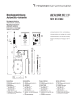
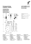
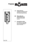
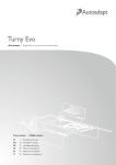
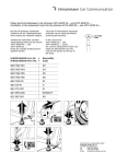
Montageanleitung
Einbausatz
Installation instructions
Mounting set
Instruction de montage
Set de montage
AUTA 74 F W 202
Bestell-Nr. / Ord. code / N° de cde.
823 130-001
823 130-003*
B 6 6 82 8093*
Für Automatic-Antennen-Grundtyp
For automatic antenna basic type
Pour l'antenne automatique de base
~50°
AUTA 6000 KE-F 474
921 601-001
921 601-003*
B 6 6 82 8091*
Zum Einbau in:
For installation in:
Pour montage sur:
A059/1
495 750-335
Mercedes C-Klasse-Limousinen
C 180 / C 200 / C 220 / C 230 /
C 230 Kompressor / C 280
C 200 Diesel / C 220 Diesel /
C 250 Turbodiesel
C 36 AMG
Baureihe / Series / Série W 202
6.93 ➝
* Lieferung über Mercedes-Benz (Teile-Zubehör)
* Delivery by Mercedes-Benz (Accessories)
Fig. 1
* Livraison par Mercedes-Benz (Accessoires)
Fig. 2
Fig. 5
Fig. 8
Fig. 3
Fig. 6
Fig. 9
Fig. 10
L
Fig. 4
2
R
Fig. 7
D
Einbauanleitung
Der Einbau der Automatic-Antenne
AUTA 6000 KE-F 474 mit dem Einbausatz
AUTA 74 F W 202 erfolgt bei den angegebenen
Mercedes-Benz C-Klasse-Modellen in den linken
hinteren Kotflügel.
Zur Sicherheit Batterie Minuspol abklemmen.
Fig. 11
Im Kofferraum die linksseitige Auskleidung entfernen.
Für Kabelverlegung hintere Sitzbank und
-kissen ausbauen. Kabelkanal entlang der Türdichtung und der linksseitigen Schweller durch
Abheben der Deckleisten öffnen.
Fußmatten, linke Seitenverkleidung und
Abdeckung unter Instrumententafel vorne entfernen.
An der Einbaustelle nach Fig. 1 die beiliegende
Bohrschablone anlegen, das Karosserieloch
anzeichnen und maßhaltig einarbeiten. Zum
Schutz des Lackes vorher mit Klebeband abkleben. Die Bohrung entgraten, gegen Korrosion
die blanke Kante mit Grundlack bestreichen und
antrocknen lassen.
Fig. 12
Fig. 13
Das Antennenkabel und die Motorleitungen
zusammen mit dem bereits verlegten Leitungssatz durch die Mehrfachtülle im Kabelkanal entlang der linken Einstiegsleiste zum Fahrersitz
verlegen. Das Antennenkabel und die weiße
Ader entlang der Quertraverse zum Mitteltunnel
verlegen (Fig. 11 und 12). Verkleidung am Tunnel
etwas abheben, die Kabel hinter den Einbauraum für das Autoradio verlegen und einstecken.
Motorleitung wie folgt anschließen:
Weiße Ader (mit 2,8 Timerkontakt) an für
Steuerung von Automatic-Antennen vorgesehener
Kontaktstelle A5 am Empfängeranschlußstecker
einrasten.
Rote Ader (mit Timerkontakt im Steckergehäuse)
dem vorhandenen Leitungssatz nach zum
Sicherungsträger verlegen. Den Sicherungsträger von der Motorraumseite her lösen
(6 Schrauben am Rahmen und 1 Schraube am
Sicherungsträger - Fig. 13). Der Anschluß erfolgt
über die 7,5-A-Sicherung an der für die Motorantenne vorgesehenen Kontaktstelle "21/3"
(siehe Hinweis im Deckel). Zum Einsetzen den
Sicherungsriegel "A" ziehen, Steckergehäuse
"B" einsetzen und danach wieder verriegeln
(Fig. 14).
Schwarze Ader (mit Kabelschuh) im Kofferraum an vorhandener Masse-Kontaktschraube
anschließen (Fig. 9 und 11).
Die Antenne für den Einbau vorbereiten.
Befestigungsteile "L + R" am Gehäuse in abgebildeter Position einsetzen (Fig. 4).
Halter am Befestigungsteil "R" einhängen und
am Befestigungsteil "L" mit M5-Sechskantschraube, Scheibe und Mutter befestigen (Fig. 4,
5 und 6).
Die Dichttülle von oben in das Karosserieloch
einsetzen (Fig. 2 und 7).
Der Antenne beiliegende Edelstahlklebefolie von
unten um die eingesetze Karosserietülle anlegen
und gleichmäßig an das Kotflügelblech andrücken (Fig. 2 und 3).
Fig. 14
3
Bei vorhandenem Antennenloch prüfen, ob
Edelstahlklebefolie in entsprechender Größe
bereits eingeklebt ist.
Das Antennenkabel am Antennenstutzen fest
anschrauben und die Motorleitung einstecken
(Fig. 6).
Die Antenne vom Kofferraum aus in die bereits
eingesetzte Dichttülle eindrücken (Fig. 7 und 8);
dazu empfiehlt es sich, den Kugelstutzen vorher
mit etwas Fett zu bestreichen, z. B. mit AUTA 115.
Darauf achten, daß die Federzungen für den
kapazitiven Massekontakt an der eingeklebten
Edelstahlfolie gespannt anliegen (Fig. 8).
Halter an dem vorhandenen Langloch der Verstrebungswand anschrauben (Fig. 9).
Das Masseband an vorhandenem Massekontakt Schraubanschluß M6 anschließen (Fig. 8 und 9).
Nach Beendigung der Installation Batterie wieder
anklemmen und Antenne durch Einschalten des
Radios ausfahren. Die Neigung des Teleskops
kontrollieren, die Stellung der Antenne eventuell
korrigieren und danach die Schrauben am Halter
fest anziehen (Fig. 9 und 11).
Auskleidung im Kofferraum, entfernte Verkleidungen und den Rücksitz im Innenraum wieder
einbauen.
Reinigen Sie bitte das Teleskop möglichst oft
von anhaftendem Staub und Schmutz. Verwenden Sie nur ganz wenig von unserem Spezialfett
in Tuben AUTA 235 oder benutzen Sie unser
Autoantennen-Pflegetüchlein AUTA 135, das
gleichzeitig reinigt und fettet.
GB
Installation instructions
Installation of the automatic antenna
Auta 6000 KE-F 474 with the installation set
Auta 74 F W 202 is appointed left-side in the
rear wings of the stated Mercedes car types
Class C.
Disconnect battery for security.
Remove left-side lining in the luggage-boot.
For cable laying detach the back seat including
the backrest. Open the cable duct alongside
the door sealing and the left threshold by lifting
the trims.
Remove the floor mats, the left-side lining and
the cover below the dashboard in the front of
the car cabin.
Apply the attached drilling pattern according to
Fig.1, mark the installation place and properly
drill the hole. Before drilling cover the paintwork
with adhesive tape for protecting. Remove the
burr, spread the bare edge with primer to protect
against corrosion and allow to dry.
Pass the antenna cable and the motor cables
together with the cable set being already installed
through the multiple grommet inside the cable
duct alongside the left threshold to the driver's
seat. Lay the antenna cable and the white lead
along the cross traverse to the centre tunnel
(Fig. 11 and 12). Lift the lining of the tunnel,
pass the cables behind the receiver and plug-in.
Technische Änderungen vorbehalten.
Dieses Produkt ist nach seiner Verwendung
entsprechend den aktuellen Entsorgungsvorschriften Ihres Landkreises / Landes / Staates als
Elektronikschrott einer geordneten Entsorgung
zuzuführen.
Die beschriebenen Leistungsmerkmale sind nur
dann verbindlich, wenn sie bei Vertragsabschluss
ausdrücklich vereinbart wurden. Diese Druckschrift
wurde von Hirschmann Car Communication GmbH
auf Übereinstimmung mit den beschriebenen
Antennen und Antennenzubehör (Kabel, Stecker
etc.) geprüft. Dennoch können Abweichungen
hinsichtlich der Richtigkeit oder Genauigkeit
nicht ausgeschlossen werden, sodass Hirschmann für die vollständige Übereinstimmung
keine Gewähr übernimmt. Hirschmann behält
sich das Recht vor, den Inhalt dieser Druckschrift
ohne Ankündigung zu ändern.
Connecting the motor cable:
Connect the white lead (with 2.8 size timer
contact) to contact no. A5 at the receiver plug
provided for automatic antenna control.
Pass the red wire (with timer contact in
connector body) along with the already installed
cable set up to the fuse terminal. Loosen the
fuse terminal from the motor compartment
(6 screws at the frame and 1 screw at the fuse
holder, Fig.13). Connect via the 7,5-A-fuse to
terminal "21/3" provided for automatic aerial
control (see instructions inside the lid). For
insertion pull the safety lock bolt "A", insert the
connector body "B" and then lock again (Fig. 14).
Connect the black lead (with cable lug) in the
luggage-boot to the provided earthing screw
(Fig. 9 and 11).
Tighten the antenna cable to the antenna case
and plug-in the motor cable (Fig.6).
Insert the antenna from the luggage-boot
through the sleeve (Fig. 7 and 8); it is recommended to preciously apply some grease, e.g.
AUTA 115 to the spherical antenna head. Make
sure that the spring contacts for capacitive
grounding are properly connected to the adhesive foil (Fig. 8).
Fasten the bracket at the existing oblong hole
to the brace wall Ffig. 9).
Fix the earthing tape to the provided earth
contact with M5 screw clamp (Fig. 8 and 9).
After completion of installation reconnect battery
and extend the antenna by switching on the
radio. Check the angle of the telescope and the
position of the antenna, adjust if necessary and
then tighten the screws at the bracket (Fig. 9
and 11).
Replace the carpeting inside the luggage-boot
and all removed linings inside the car and reinstall the back seat.
Please clean the telescope as often as possible
of adhering dust and dirt. Use only a little of our
special grease AUTA 235 supplied in tubes or
our car antenna tissue AUTA 135 for both cleaning and greasing.
Right of modification reserved.
After its use, this product has to be processed
as electronique scrap to a proper disposal
according to the prevailing waste disposal regulations of your community / district / country /
state.
The performance features described here are
binding only if they have been expressly guaranteed in the contract. This publication has been
created by Hirschmann Car Communication GmbH
according to the best of our knowledge.
Hirschmann reserves the right to change the
contents of this manual without prior notice.
Hirschmann can give no guarantee in respect of
the correctness or accuracy of the details in this
publication.
Prepare the antenna for installation.
Insert the fixing parts "L+R" to the housing at
the position as shown (Fig. 4).
Hang up the bracket to the fixing part "R" and
fasten to the fixing part "L" using the M5 hex
head screw, washer and nut (Fig. 4, 5 and 6).
Insert the sealing sleeve from top into the car
body hole (Fig. 2 and 7).
Apply the stainless-steel adhesive foil enclosed
with the antenna from below around the inserted
sleeve and properly press against the car body
sheet (Fig. 2 and 3).
The antenna hole may be already provided; in
this case check whether a suitable steel foil has
been already applied, too.
4
F
Instruction de montage
Le montage de l'antenne automatique
Auta 6000 KE-F 474 avec le jeu d'installation
Auta 74 F W 202 se fait sur les modèles de la
"Classe C" de Mercedes-Benz ci-indiqués sur
l'aile arrière gauche.
Pour des raisons de sécurité, débrancher le
pôle négatif de la batterie.
Enlever le revêtement du côté gauche du coffre.
Pour la pose du câble, démonter la banquette
et le coussin arrières. Ouvrir le caniveau de
câbles le long du joint de portière et du marchepied gauche en levant les couvre-joints. Eloigner
les moquettes, le revêtement latéral gauche
ainsi que le revêtement au-dessous du tableau
de bord à l'avant.
Appliquer le gabarit de perçage ci-inclus à l'endroit de montage selon Fig. 1, marquer le trou
de perçage sur la carrosserie et percer précisément. Auparavant, coller un ruban adhésif pour
protéger la laque. Supprimer les bavures du
perçage, enduire le bord nu de laque de base
comme protection contre la corrosion et laisser
sécher.
Poser le câble d'antenne et les conduites du
moteur avec le jeu de câbles déjà posé par le
passe-câble multiple dans le caniveau de câbles
sous le rebord d'accès gauche jusqu'au siège
du conducteur. Poser le câble d'antenne et la
conduite blanche le long de l'entretoise transversale jusqu'au caniveau moyen (Fig. 11 et 12).
Soulever légèrement le revêtement du caniveau,
poser le câble d'antenne derrière l'autoradio et
brancher.
Brancher les conduites du moteur comme suit:
Encliqueter la conduite blanche (avec contact
timer 2,8) dans le contact A5 prévu pour la
commande de l'antenne automatique à la fiche
du récepteur.
Poser la conduite rouge (avec contact timer
au connecteur) le long du jeu de câbles existant
à la boîte à fusibles. Dégager la boîte à fusibles
du côté du moteur (6 vis au châssis et 1 vis à la
boîte à fusibles, Fig. 13). Elle sera branchée par
le fusible 7,5 A au contact "21/3" prévu pour
l'antenne automatique (voir avis dans le couvercle). Ouvrir le verrouillage "A", enficher le
connecteur "B" et ensuite verrouiller
(Fig. 14).
Brancher la conduite noire (avec cosse de
câble) à la vis de contact de masse dans le
coffre (Fig. 9 et 11).
Préparer l'antenne au montage.
Mettre les pièces de fixation "L+R" au boîtier
dans la position de la Fig. 4.
Accrocher le support à la pièce de fixation "R"
et fixer à la pièce de fixation "L" avec le boulon
hexagonal M5, la rondelle et l'écrou (Fig. 4, 5 et 6).
Placer le manchon étanche d'en haut dans le
perçage de la carrosserie (Fig. 2 et 7).
Mettre la feuille adhésive d'acier fin, qui se trouve
jointe à l'antenne, d'en bas autour
5
du manchon de carrosserie déjà mis et
presser également contre la tôle d'aile (Fig. 2 et 3).
S'il y a déjà un trou d'antenne, veuillez vérifier si
la feuille adhésive d'acier fin bien taillée a été
déjà mise.
Visser à fond le câble d'antenne à la rallonge
d'antenne et enficher la conduite du moteur
(Fig. 6).
Du côté du coffre, presser l'antenne dans le
manchon étanche déjà mis (Fig. 7 et 8); pour
cela nous vous recommandons de commencer
par enduire la rallonge à bille d'un peu de graisse,
p. ex. d' AUTA 115. Faire attention à ce que les
ressorts pour le contact capacitif à la masse
aient un contact tendu à la feuille adhésive
d'acier fin (Fig. 8).
Visser le support au trou oval existant à l'entretoise (Fig. 9).
Brancher la bande de mise à la masse au raccord fileté de contact à la masse M6 existant
(Fig. 8 et 9).
Une fois finie l'installation, rebrancher la batterie
et sortir l'antenne en mettant en marche la radio.
Contrôler l'inclinaison du télescope; si besoin
est, corriger la position de l'antenne et ensuite
serrer à fond les vis au support (Fig. 9 et 11).
Remonter le revêtement du coffre ainsi que les
autres revêtements démontés et le siège arrière.
Veuillez nettoyer le télescope le plus souvent
possible de la poussière adhérente et de la
saleté. N'utilisez que très peu de notre graisse
spéciale en tube AUTA 235 ou bien notre essuieantenne AUTA 135 qui nettoie et graisse en
même temps.
Sous réserve de modifications techniques.
Ce produit doit être éliminé en tant que déchet
électronique conformément au réglement actuel
sur l'élimination des déchets de votre département / région / pays.
La société Hirschmann Car Communication GmbH
ne se porte garante de la véracité des informations
techniques que si elles ont été spécifiées de
manière expresse à la signature du contrat.
Le contenu de ce document a été minutieusement contrôlé afin de s’assurer qu’il corresponde
bien aux antennes et accessoires (câbles,
connecteurs) décrits. Toutefois, Hirschmann ne
peut en aucun cas être tenu responsable de
l’exactitude de ces informations. Hirschmann se
réserve le droit de modifier sans préavis le contenu de ce document.
Schaltschema
Wiring diagram
Schéma de câblage
Antenne
Antenna
Radio
+12V
150 ws
sw
rt
5 A … 7,5 A
A127/5
K 30
–
+
12 V*
Gebrauchs- und
Pflegeanleitung
AUTA 6000 ...
Für den Kunden bestimmt
Batterie /
Battery /Batterie
* Betriebsspannung /
Operating voltage /
Tension de service
9 - 16 V–
Bitte die beigefügte Gebrauchsund Pflegeanleitung mit
Garantiekarte und den beiden
Autoantennen-Pflegetüchlein
(AUTA 135) dem Kunden aushändigen.
Please hand over to the customer the enclosed instructions
for use and maintenance with
guarantee certificate as well as
the two car antenna tissues
(AUTA 135).
Veuillez transmettre au client le
mode d'emploi et d'entretien
ci-joint avec le bulletin de
garantie et les deux essuiesantenne (AUTA 135).
Radio einschalten - Antenne fährt
aus.
Radio ausschalten - Antenne fährt
ein.
Switch radio on - antenna will
extend.
Switch radio off - antenna will
retract.
Mettre en marche la radio l'antenne sort.
Arrêter la radio l'antenne rentre.
Einfacher Teleskopwechsel ohne
Ausbau der Antenne möglich.
Easy telescope exchange possible
without antenna removal.
Possibilité d'échanger simplement
le télescope sans démonter l'antenne.
Code number: 11
Chiffre: 11
Replacement mast
Ord. code: 823 112-111
Télescope de rechange
N° de cde.: 823 112-111
Please state ordering codes when
ordering spare parts.
Veuillez commander les pièces
détachées sous les numéros indiqués.
Instructions for use and
maintenance
Intended to the customer
Mode d'emploi et
d'entretien
Destiné au client
Kenn-Nr.: 11
11
Ersatzteleskop
Bestell-Nr.: 823 112-111
Ersatzteile bitte unter den angegebenen Nummern bestellen.
Hirschmann Car Communication GmbH
Stuttgarter Strasse 45 - 51
D - 72654 Neckartenzlingen
Tel (07127) 14-1873
Fax (07127) 14-1428
025 042-001-10-1005-N
Printed in Europe . Imprimé en Europe