1
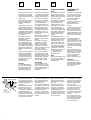
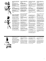
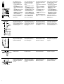
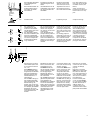
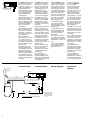
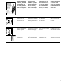
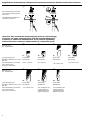
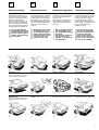
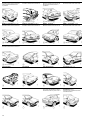
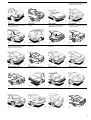
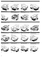
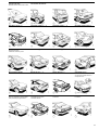
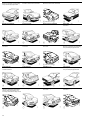
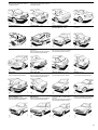
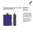
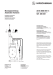
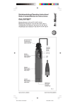
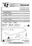
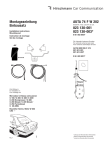
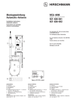
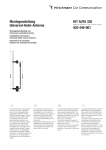
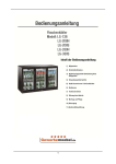
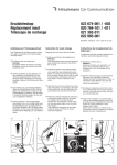
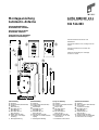
Montageanleitung
Automatic-Antenne
AUTA 6000 KE 1/11
Bestell-Nr. / Bestelnr. / Ord. code / No de Cde.
921 514-003
Montagehandleiding
Automatische antenne
Mounting instructions
Automatic antenna
Instructions de montage
Antenne automatique
Universal-Antenne für Front- und
Heckeinbau
90 cm
➁
➂
Universele antenne voor montage vóór en
achter
Universal antenna for front and rear
mounting
0 - 38°
Antenne universelle pour montage
sur aile AV et AR
➃
➄
A114/7
150 cm
485 cm
500 cm
30 cm
➀
60 cm
➅
➆
Lieferumfang
➀ Antenne
➁ Antennenkopf (822 940-001)
➂ Zubehör
➃ Motorleitung
➄ HF-Kabel 150 cm
(825 986-012)
➅ HF-Kabel 485 cm
(825 720-017)
➆ Halter (495 750-195)
8 Gebrauchs- und Pflegeanleitung
9 Montageanleitung
Samenstelling
➀ Antenne
➁ Antennekop (822 940-001)
➂ Toebehoren
➃ Motorkabel
➄ HF-kabel 150 cm
(825 986-012)
➅ HF-kabel 485 cm
(825 720-017)
➆ Houder (495 750-195)
8 Gebruiks- en onderhoudsaanwijzing
9 Montagehandleiding
Scope of delivery
➀ Antenna
➁ Antenna head (822 940-001)
➂ Accessories
➃ Motor cable
➄ HF-cable 150 cm
(825 986-012)
➅ HF-cabel 485 cm
(825 720-017)
➆ Bracket (495 750-195)
8 Instructions for use and
maintenance
9 Installation instructions
Gamme de livraison
➀ Antenne
➁ Tête d'antenne (822 940-001)
➂ Accessoires
➃ Conduite de moteur
➄ HF-Kabel 150 cm
(825 986-012)
➅ Câble HF 485 cm
(825 720-017)
➆ Support (495 750-195)
8 Mode d'emploi et d'entretien
9 Instructions de montage
D
Antenna installation
Installation de
l'antenne
Die Antenne wird nur für
Fahrzeuge mit 12 V Batteriespannung geliefert,
wobei Minus am Chassis
liegen muß.
De antenne wordt alleen
voor voertuigen met 12 V
accuspanning geleverd
waarbij de minpool aan
het chassis moet zitten.
The antenna is supplied
only for cars with 12 V
battery operating voltage
with minus being connected to the chassis.
Die Antenne ist zum Einbau im vorderen, bzw.
hinteren Kotflügel bestimmt.
De antenne is bedoeld
voor inbouw in het voorc.q. achterspatbord.
The antenna is intended
for installation in the
front or rear fender.
L'antenne n'est disponible
que pour des véhicules
avec une tension de batterie de 12 V, supposé
que le pôle négatif se
trouve au châssis.
Voor de inbouw in het
voorspatbord dient in de
wielkast achter het uitbouwbare binnenspatbord, beschermd tegen
opspattend water, voldoende ruimte beschikbaar te zijn.
If the antenna is to be
installed in the front fender, sufficient space
must be available in the
wheel house behind the
removable wheel-house
inner panel (protected
against direct splash
water).
Für einige Fahrzeugtypen
finden Sie den Einbauvorschlag in der beiliegenden Übersicht bzw.
in unserer Druckschrift
„Einbauvorschläge und
Montagetips“
DS 280 111-100.
Hinweis
Zur Sicherheit die Verbindung zum BatterieMinuspol abklemmen,
dazu Anweisung des
Herstellers beachten!
A115/4
entgraten
afbramen
remove the burr
enlever la bavure
2
?
F
Inbouw antenne
Der Einbau am Fahrzeugheck erfolgt vom
Kofferraum aus.
Der Einbauort liegt hierbei in der Regel hinter
der Heckscheibe, wobei
für das Antriebsgehäuse
im Kofferraum genügend
freier Raum (hinter dem
Radlauf) vorhanden sein
muß.
?
GB
Antenneneinbau
Zum Einbau in den vorderen Kotflügel muß im
Radhaus hinter dem ausbaubaren Innenkotflügel,
geschützt gegen direktes
Spritzwasser, genügend
freier Raum zur Verfügung stehen.
Ø 16,5…22 mm
NL
An der Einbaustelle ein
Loch entsprechend der
Angabe zum verwendeten
Antennenkopf bohren
(siehe S. 8).
Das Karosserieblech auf
der Unterseite um die
Bohrung herum blank
machen und mit Kontaktschutzfett bestreichen.
Dadurch wird eine gute
Masseverbindung für die
Abschirmung und Schutz
vor Korossion erreicht.
De inbouw aan de achterkant van het voertuig
geschiedt vanuit de kofferbak.
De plaats van inbouw
ligt hierbij in de regel
achter de achterruit
waarbij voor de besturingsunit in de kofferruimte voldoende ruimte
(achter de wielen)
beschikbaar moet zijn.
Voor een aantal types
voertuigen vindt U het
inbouwadvies in het bijgevoegde overzicht c.q. in
onze brochure ”Inbouwadviezen en montagetips“ DS 280 111-100.
The installation place is
normally behind the rear
window; there must be
sufficient space in the
boot for the drive case
(behind the wheel box).
For several car types you
will find the installation
suggestion in the summary being enclosed or
in our publication
„Installation guide“
DS 280 121-10.
Note
Disconnect battery minus
for security, according to
the instructions of the
manufacturer!
Aanwijzing
Voor de veiligheid de
verbinding naar de minpool van de accu afklemmen, daarbij letten op de
aanwijzingen van de
fabrikant!
Op de inbouwplaats conform een gat boren voor
de te gebruiken antennekop (zie S. 8).
Drill a hole at the installation place according
the used antenna head
(see p. 8).
Het carosseriemetaal aan
de onderkant rondom het
gat blank maken en met
contactbeschermingsvet
insmeren. Daardoor
wordt een goede hechting voor afscherming en
bescherming tegen roest
bereikt.
Bare the body sheet
underneath around the
hole and cover it with
protecting grease. Thus
a satisfactory ground
connection for the antenna cable screening and
protection against corrosion is ensured.
L'antenne est destinée à
être montée sur le
garde-boue avant ou
arrière.
Pour le montage dans le
garde-boue avant, l'espace doit être suffisant
dans le passage de roue
derrière la doublure d'aile
démontable et protégé
des éclaboussures directes.
En règle générale, I'endroit de montage se
trouve derrière la lunette
arrière pourvu qu'il y ait
un espace suffisant pour
le boîtier moteur dans le
coffre (derrière le passage
de roue).
Pour quelques types de
véhicule vous trouverez
notre conseil de montage
dans le tableau ci-joint
ou bien dans notre imprimé ”Installation
guide” DS 280 121-100.
Remarque
Pour des raisons de
sécurité, débrancher le
pôle négatif de la batterie,
selon les données du
constructeur.
A l'endroit de montage
perçer un trou selon les
données qui se réfèrent
à la tête d'antenne utilisée (voir p. 8).
Sur la face intérieure de
la carrosserie, mettez la
tôle à blanc autour du
perçage et prenez soin
de l'enduire impeccablement de la graisse de
contact.
Vous assurez ainsi à la
fois un parfait contact de
masse pour le blindage
et une protection anticorrosive efficace.
Die separat verpackten
Befestigungsteile bereitlegen.
Ø 16,5 mm
0 - 26°
Bei Bohrungen mit
Ø 16,5 mm sind die beiden Stege an der Wippe
abzubrechen.
Der Neigungswinkel ist
dann auf max. 26° eingeschränkt.
A114/2
Bei einer Bohrung von
Ø 20 - 22 mm sind die
Stege an der Wippe nicht
abzubrechen.
Der Neigungswinkel
kann dann bis zu 38° betragen.
Das HF- Anschlußkabel
(➄ Fronteinbau, ➅ Heckeinbau) am Antennenstutzen anschrauben.
Die unteren Teile gemäß
Abbildung aufsetzen.
Ø 20 mm
A114/2
0 - 38°
Die Antenne von unten
in die Karosserie einsetzen. Die Wippe so drehen, daß sie rund um die
Bohrung anliegt.
Die Halbkugel mit der
Dichtunterlage von oben
durch die Bohrung in der
auf der Unterseite anliegenden Wippe einfügen.
Die Halbschale und die
Mutter aufsetzen. Die
Mutter leicht anziehen.
Weitere Antennenköpfe
für schmale Kotflügel
bzw. Neigung bis 68°
können verwendet werden (siehe Übersicht S.8).
Bei Bedarf kann die Stutzenstellung beliebig
gewählt werden.
Prepare the fixing parts
enclosed in a separate
plastic bag.
Préparer les pièces de
fixation emballées séparément.
For holes of Ø 16,5 mm
the two bars at the lower
spherical half should be
broken off.
In this case the car body
inclination is limited to
max. 26°.
Dans les perçages de
16,5 mm de Ø les deux
barrettes doivent être
rompues à la bascule.
L'inclinaison de la carrosserie peut être max. 26°.
Bij een gat van Ø 20 22 mm de verbindingsstukken op de kanteltoets niet afbreken.
De hellingshoek kan dan
tot 38° bedragen.
For a hole of
Ø 20 - 22 mm the two
bars at the lower spherical half should not be
broken off.
In this case the car body
inclination can be about
38°.
De HF-aansluitingskabel
(➄ inbouw voor, ➅ inbouw achter) op het
antenne-aansluitstuk
schroeven.
De onderste gedeeltes er
volgens de afbeelding
opzetten.
De antenne van onderen
af in de carrosserie
plaatsen. De kanteltoets
zo draaien dat hij rond
om het gat zit.
De halve bol met het
afdichtingsdeel van
boven door het gat in de
aan de onderzijde liggende kanteltoets plaatsen.
De halve bol en de moer
er opzetten. De moer
licht aandraaien.
Er kunnen andere antennekoppen voor smalle
spatborden c.q. een hoek
tot 68° gebruikt worden
(zie overzicht S.8).
Fasten the HF connection cable (➄ front
mounting, ➅ rear mounting) to the antenna.
Attach the lower parts as
per the drawing.
Insert the antenna from
underneath into the
hole. Please see that the
lower spherical half has
full contact around the
hole.
Slide the sealing washer
and the upper sperical
half over the telescopes
and take care that the
upper spherical half
coincides with the lower
spherical half.
Put on the adapting
cover and the hexagonal
nut. Tighten the hexagonal nut slightly.
For further antenna heads
for small fenders or fender inclinations up to 68°
see summary page 8.
Dans les perçages de
20 - 22 mm de Ø les
deux barrettes à la bascule ne doivent pas être
rompues.
L'inclinaison de la carrosserie peut être max. 38°.
Visser le câble de connexion HF sur le manchon
d'antenne .
(➄ montage à l'avant,
➅ montage à l'arrière)
Placer les pièces inférieures selon illustration.
Introduisez l'antenne par
le bas dans l'orifice de la
carrosserie et tournez la
pièce basculante jusqu'à
ce qu'elle épouse parfaitement la paroi intérieure
de l'orifice.
Mettez en place, par le
haut, la demi-spère et le
joint et ajustez-les, à travers l'orifice, à la pièce
basculante..
Glissez la demi-coquille
et l'ecrou sur l'antenne
et serrez légèrement.
Pour des têtes d'antennes
pour des ailes étroites ou
des inclinaisons jusqu'à
68° voir tableau des têtes,
page 8.
Indien nodig kan de
plaats van het aansluitstuk willekeurig gekozen
worden.
If necessary the position
of the antenna connection socket can be optionally selected.
En cas de besoin la position de la rallonge peut
être choisie selon vos
besoins.
Daartoe de torxschroef
losmaken, de beschermbuis conform de gewenste plaats van de antennekop draaien en aansluitend weer aantrekken.
To do so, loosen the torxscrew, from the portective tube to the desired
position of the antenna
head and then tighten
the screw again.
A cet effet desserrer la
vis torx, faire tourner le
tube protecteur selon la
position désirée de la
tête d'antenne et alors
visser à fond.
A118/3
Dazu die Torx-Schraube
lösen, das Schutzrohr
gemäß der gewünschten
Stellung des Antennenkopfes drehen und
anschließend wieder
anziehen.
De apart verpakte bevestigingsonderdelen klaar
leggen.
Bij gaten met Ø
16,5 mm dienen de
twee verbindingsstukken
op de kanteltoets afgebroken te worden.
De hellingshoek is dan
op max. 26° beperkt.
3
Zur Festlegung der
Teleskopneigung die
Antenne ausfahren:
A119/5
ws
rt
sw
For setting the telescope
inclination extend the
antenna:
Faire sortir l'antenne afin
de déterminer l'inclinaison du télescope:
– Plug-in the connection
cable.
– Connect the black
cable (sw) to minus,
then
– the red cable (rt) to
plus, finally
– for extending the
white cable (ws) also
to plus.
– Enficher les conduites
de raccordement.
– Raccorder la conduite
noire (sw) au pôle
négatif, puis
– la conduite rouge (rt)
au pôle positif et ensuite
– pour sortir l’antenne,
raccorder la conduite
blanche (ws) au pôle
positif de la batterie.
– Anschlußleitung einstecken.
– Die schwarze Leitung
(sw) an den Minuspol,
dann
– die rote Leitung (rt) an
den Pluspol, dann
– zum Ausfahren die
weiße Leitung (ws) an
den Pluspol der Batterie anschließen.
– aansluitkabel er insteken.
– de zwarte draad (sw)
aan de minpool, dan
– de rode draad (rt) aan
de pluspool, dan
– voor het naar buiten
halen de witte draad
(ws) aan de pluspool
van de accu aansluiten.
Zum Einfahren weiße
Leitung (ws) wieder
abnehmen.
Voor het naar binnen
halen de witte draad
(ws) er weer afhalen.
Der obere Knopf am ausgefahrenen Teleskop
muß mindestens 100 mm
innerhalb des Fahrzeugumrisses liegen.
De bovenste knop op de
uitgetrokken telescoop
moet minstens 100 mm
binnen de voertuigomtrek liggen.
The top of the fully extended telescope must
be at a distance of 100
mm minimum from the
car outline.
Le bouton supérieur du
télescope sorti doit se
trouver au moins à 100
mm à l'intérieur de la silhouette du véhicule.
Die notwendige Halterlänge und -stellung entsprechend festlegen.
De noodzakelijke houderlengte en -plaats conform vastleggen.
Determine the length
and the position of the
bracket as required.
Déterminer la longueur
et la position requise du
support.
Halter richten.
Houder richten.
Adjust the bracket.
Ajuster le support.
An der Antenne kann der
Halter in verschiedenen
Varianten angebracht
werden.
De houder kan op de
antenne in verscheidene
varianten aangebracht
worden.
The bracket can be
applied to the antenna in
different positions.
Pour la fixation du support à l'antenne il y a
plusières variantes.
For retracting only disconnect the white cable
(ws).
Pour faire rerentrer,
débrancher la conduite
blanche (ws).
A120
≥100 mm
Voor het vastleggen van
de telescoophoek de
antenne naar buiten
halen:
A121
;;;
;
;
;
x
A123
A122
x
2. Variante
4
1. Variante
A124
Tenslotte de houder op
de besturingsunit vastzetten.
Finally fix the bracket
with tin screws to the
drive case (see arrow).
Die Sechskantmutter am
Antennenkopf und die
Schrauben am Halter
fest anziehen.
de zeskantemoer aan de
antennekop en de schroeven aan de houder vast
aantrekken.
Tighten the hex nut on
the antenna head and
the screws at the bracket.
Anziehmoment
Aandraai moment
Tightening torque
Couple de serrage
HF- und Motoranschlußleitung in den
Innenraum und weiter
zum Einbauort des Autoradios verlegen.
Zur Abdichtung (besonders bei Fronteinbau) die
konische 2 Stufentülle
über die Kabel aufsetzen
und in die entsprechende Durchführungsbohrung eindrücken.
HF- en motoraansluitingskabel in het interieur en
verder naar de plaats
van inbouw van de autoradio leggen.
Voor de afdichting (in
het bijzonder bij inbouw
aan de voorkant) het
konische 2-trapsmondstuk over de kabel heen
zetten en in het daarvoor
bestemde doorvoergat
drukken.
Install the RF and engine
connection cable in the
passenger compartment
and route it to the installation location of the car
radio.
For sealing purposes
(especially in the case of
front installation), place
the 2 notched conical
grommets over the cable
and push into the respective bushing holes.
Poser les câbles de connexion HF et moteur
dans l'habitacle puis
dans l'emplacement de
montage de l'autoradio.
Afin d'étancher, (en particulier en cas de montage
à l'avant), poser les 2
passe-câbles étagés
coniques sur les câbles
et les enfoncer dans les
perçages de traversée.
De kabels als volgt aansluiten: (zie hiervoor het
schakelschema S.6).
Connect the leads as follows (see also the wiring
diagram, page 6):
De zwarte draad (sw)
aan de minpool (voertuigmassa) aansluiten; daartoe de bijgevoegde
kabelschoen Ø 6,5 of
platte steekhuls 6,3-1 er
aan vastmaken.
Connect the black lead
(sw) to minus (car chassis); for that purpose
crimp either the cable
6.5 dia. or the flat receptacle size 6.3-1 to the
lead (both are enclosed).
Brancher les conduites
comme suit (voir aussi le
schéma de câblage,
page 6):
Op de rode draad (rt) de
geïsoleerde platte steekhuls vastzetten. De
kabelzekering er opsteken
en met de verbindingsleiding direct met het op
de pluspool geschakelde
contact (K 30) met de
autozekeringen of met
de lichtschakelaar verbinden.
Pinch the sleeve plug to
the red cable (rt). Plug in
the fuse, connect the linking lead to the contact
(K 30) which is directly
connected to the battery
plus pole on the car fuses
or to the light switch.
Ø 4,8 mm
;;;;;
;
;
Zum Abschluß den Halter
am Antriebsgehäuse
arretieren.
arretieren
vastzetten
fix
arrêter
Visser à fond l'écrou
hexagonal à la tête d'antenne et les vis au support.
A125/4
rt
sw
M013
Ø 12-15 mm
;;;;;;; ;;;;;;
Ø 19-21 mm
3,5 ±0,5 Nm
Pour finir arrêter le support avec des vis en tôle
au boîtier moteur (voir
flèche).
5A
Wagensicherungen
Autobeveiligingen
Car fuses
Fusibles de bord
K 30
ø 6,5
ø 6,3
+
–
Batterie
12 V
Die Leitungen wie folgt
anschließen: (siehe hierzu auch das Schaltschema, S. 6).
Die schwarze Leitung
(sw) an Minuspol (Fahrzeugmasse) anschließen;
dazu den beiliegenden
Kabelschuh Ø 6,5 oder
Flachsteckhülse 6,3-1
aufquetschen.
Auf die rote Leitung (rt)
die isolierte Flachsteckhülse aufquetschen. Die
Kabelsicherung aufstecken und mit der Verbindungsleitung an direkt
zum Pluspol geschalteten
Kontakt (K 30) an den
Wagensicherungen oder
am Lichtschalter aufstecken.
Brancher la conduite
noire (sw) au pôle négatif (masse du véhicule);
pour cela empreindre la
cosse de câble ci-jointe
de Ø 6,5 ou la douille à
fiche plate 6,3-1.
Pincer la douille plate
sur la conduite rouge
(rt). Connecter le fusible
de câble et brancher le
câble de liaison au
contact (K 30) qui est
directement raccordé au
pôle positif de la batterie.
5
A126
+12V
ws
Die weiße Steuerleitung
(ws) und das Antennenkabel zum AutoradioEinbauort verlegen.
Sofern am Autoradio ein
entsprechender Anschlußkontakt für Automatic-Antennen vorhanden, die beiliegende
Flachsteckhülse 2,8-1
aufquetschen.
De witte besturingsleiding (ws) en de antennekabel naar de inbouwplaats van de autoradio
leggen. Voor zover aan
de autoradio een aansluitingscontact voor
automatische antennes
aanwezig is, de bijgevoegde platte steekhuls
2,8-1 er aan vastmaken.
Der Stecker am HF-Kabel
kann je nach Bedarf
gerade oder als Winkelstecker verwendet werden. Das Abbiegen über
den Führungsrücken
bitte nur von Hand
durchführen.
De stekker aan de HFkabel kan indien nodig
recht of als hoekstekker
gebruikt worden. Het
afbuigen via de geleiderug alleen met de hand
uitvoeren.
Bei richtigem Anschluß
fährt die Antenne aus,
wenn das Autoradio eingeschaltet - wieder ein,
wenn das Autoradio ausgeschaltet wird.
Beim erstmaligen
Betrieb kann es vorkommen, daß die Antenne
erst ausfährt, wenn das
Autoradio nochmals kurz
aus- und wieder eingeschaltet wird.
Dies kann auch nach
dem Wiederanschluß
der abgeklemmten Batterie erforderlich sein
(Aktivierung der elektronischen Steuerschaltung).
Bij een juiste aansluiting
komt de antenne naar
buiten als de autoradio
wordt aangezet - en gaat
weer naar binnen als de
autoradio wordt uitgezet.
Als dit voor de eerste
keer gedaan wordt, kan
het gebeuren dat de
antenne pas naar buiten
komt als de autoradio
nog een keer kort aan- en
uitgezet wordt.
Dit kan ook na heraansluiting van de afgeklemde accu nodig zijn
(activering van de electronische besturingsschakeling).
Die Schaltung ist verpolungssicher, funktioniert
jedoch nur bei richtigem
Anschluß.
De schakeling is
beschermd tegen verkeerd aansluiten aan de
polen, maar functioneert
echter alleen als hij juist
is aangesloten.
Schaltschema
Schakelschema
Pass the white control
lead (ws) and the antenna
cable to the installation
place of the car radio. lf
a suitable blade contact
for automatic antennas
is provided at the radio,
crimp the flat receptable
2.8-1 to the cable end.
The plug at the HF cable
can be used staight or, if
required, as an angled
plug. Please bend the
plug only by hand.
If connected properly,
the antenna extends
when switching on the
radio and retracts when
switching off.
On first operation, the
antenna probably does
not extend before switching on and off the
radio again.
This may be necessary,
too, after reconnection
of the battery (to activate
the electronic control circuit).
The circuit is designed
pole-confusing-proof,
but operates only if properly connected.
Wiring diagram
Radio
+12V
150 ws
sw
rt
5A
A127/2
K 30
+
12 V*
6
Batterie /Accu
Battery /Batterie
Le connecteur au câble
H. F. peut être utilisé, si
besoin est, droitement
ou comme fiche coudée.
Ne la tordre que manuellement par dessus le
tube conducteur.
Si l'antenne est correctement raccordée, elle sortira quand l'autoradio est
mise en marche, et elle
rentrera quand la radio
est arrêtée.
Lors du premier service
de la radio il est possible
que l'antenne sortira
seulement, si l'autoradio
est brièvement arrêtée et
ensuite mise en marche
de nouveau.
Cela peut être aussi
nécessaire après le raccordement de la batterie
débranchée (activation
du circuit de commande
électronique).
La commutation est
protégée contre une
polarisation incorrecte, et
elle ne marche qu'après
un branchement correct.
Antenne
Antenna
–
Poser la conduite de
commande blanche
(ws) et le câble
d'antenne jusqu'à l'endroit de montage de
l'autoradio. Si l'autoradio est pourvue d'une
connexion pour une
antenne automatique,
empreindre la douille à
fiche plate 2,8-1 ci-jointe.
* Betriebsspannung /
Bedrijfsspanning /
Operating voltage /
Tension de service
9 - 16 V–
Schéma de
câblage
Gebrauchs- und
Pflegeanleitung
mit Garantiekarte
AUTA 6000 ...
De bijgevoegde
gebruiks- en onderhoudsaanwijzingen
met garantiekaart en
de twee antenneonderhoudsdoekjes
(AUTA 135) aan de
klant overhandigen.
Please hand over to
the customer the enclosed instructions
for use and maintenance with guarantee
certificate as well as
the two car antenna
tissues (AUTA 135).
Veuillez transmettre
au client le mode
d'emploi et d'entretien
ci-joint avec le bulletin de garantie et les
deux essuies-antenne
(AUTA 135).
Radio einschalten –
Antenne fährt aus.
Radio ausschalten –
Antenne fährt ein.
Radio aanzetten antenne komt naar buiten.
Radio uitzetten antenne gaat naar binnen.
Switch radio on – antenna will extend.
Switch radio off – antenna will retract.
Mettre en marche la
radio – l'antenne sort.
Arrêter la radio – l'antenne rentre.
Einfacher Teleskopwechsel ohne Ausbau der
Antenne möglich.
Simpele telescoopwissel
zonder uitbouwen van
de antenne mogelijk.
Easy telescope exchange
possible without antenna
removal.
Possibilité d'échanger
simplement le télescope
sans démonter l'antenne.
Kenn-Nummer: 06
Kengetal: 06
Code number: 06
Chiffre: 06
Ersatzteleskop
Bestell-Nr.: 820 902 - 106
Vervangingstelescopen
Bestelnr.: 820 902 - 106
Repalcement mast
Ord. code: 820 902 - 106
Télescope de rechange
N° de cde.: 820 902 - 106
ah
2J
Für den Kunden bestimmt
Intended to the customer
Destiné au client
re
Ga
ra
nt
ie
Instructions for use and
maintenance incl.
guarantee certificate
Mode d'emploi et
d'entretien avec
bulletin de garantie
Bitte die beigefügte
Gebrauchs- und Pflegeanleitung mit
Garantiekarte und
den beiden Autoantennen-Pflegetüchlein
(AUTA 135) dem Kunden aushändigen.
A344
Richard Hirschmann GmbH & Co
Geschäftsbereich
Mobile Kommunikationstechnik
Postfach 1649
D-72606 Nürtingen
024 890-002-02-894-N
Printed in Federal Republic of Germany . Imprimé en République Fédérale d´Allemagne
06
7
Mitgelieferter Antennenkopf / Meegeleverde antennekop / Antenna head encluded / Tête d'antenne
1
2
Karosseriebohrung / Carosseriegat / Car body hole / Perçage de
carrosserie
Ø 16,5 mm
Ø 20 mm
Verstellbereich / Verstelbereik /
inclination / inclinaison
0 - 26°
A114/2
A114/2
0 - 38°
Übersicht über zusätzliche Antennenköpfe (nicht im Lieferumfang)
Overzicht van extra antennekoppen (niet bij levering inbegrepen)
Summary of additional antenna heads (to be ordered separately)
Tableau des têtes d'antenne additionnelles (à commander apart)
➂
➃
➄
➅
17°
32°
37°
54°
Typ / Typ / Type / Type
AUTA 8260
AUTA 8232
AUTA 8237
AUTA 8254
Bestell-Nr. / Bestelnr. / Ord. code /
Réf. No.
820 991-005
822 138-005
822 569-002
821 740-005
Karosseriebohrung / Carosseriegat / Car body hole /
Perçage de carrosserie
Ø 15,5 - 16,5 mm
Ø 17 - 18 mm
~15 x 18 mm oval
~15 x 18 mm oval
Kenn-Nr. / Kengetal /
Reference No. /
No. d'identification
➆
➇
➈
59°
64°
68 °
Typ / Typ / Type / Type
AUTA 8259
AUTA 8264
AUTA 8268
Bestell-Nr. / Bestelnr. / Ord. code /
Réf. No.
822 578-001
821 851-005
823 080-002
Karosseriebohrung / Carosseriegat / Car body hole /
Perçage de carrosserie
~15 x 29 mm oval
nach Schablone / gat
volgens sjabloon /
see template / selon
gabarit de perçage
nach Schablone / gat
volgens sjabloon /
see template / selon
gabarit de perçage
Kenn-Nr. / Kengetal /
Reference No. /
No. d'identification
8
D
NL
GB
F
Einbauvorschläge
Inbouwinstructies
Installation suggestions
Conseils de montage
1 und
Die Kennzeichnungen 2 verweisen auf die Verwen
dung des serienmäßig beiliegenden Antennenkopfes.
3 -
9
Die Kennzeichnungen zeigen an, welcher Antennenkopf an Stelle des serienmäßigen Antennenkopfes zusätzlich
für den Einbau erforderlich ist.
1 en 2 verwijst
De aanduiding naar het gebruik van de bijgevoegde standaard antennekop.
3 -
9 geven
De aanduiding aan welke antennekop ter plekke
van de standaard antennekop
daarnaast voor de inbouw
nodig is.
1 and 2 refer to the
The mark use of the enclosed standard
antenna head.
3 -
9 indicate, by
The mark witch antenna head the standard antena head should be
replaced.
1 et 2 se rapLes marquages portent à l'utilisation de la tête
d'antenne de série ci-jointe.
3 -
9 indiLes marquages quent la tête d'antenne iqui est
nécessaire pour l'installation au
lieu de la tête d'antenne
installée en série.
Wij kunnen geen verantwoording nemen voor
de aangegeven inbouwmaten. Wij verzoeken U
daarom in ieder geval te
controleren of onze
opgaven correct zijn.
We are unable to assume
any responsibility for
the installation measures
indicated.
We therefore request to
check in each case
whether our indications
are applicable.
Für die angegebenen
Einbaumaße können wir
nicht haften. Wir bitten
darum, in jedem Fall zu
prüfen, ob unsere Angaben zutreffen.
Nous ne pouvons pas
assumer la responsabilité des dimensions de
montage indiquées.
Nous vous prions de
bien vouloir vérifier en
tout cas si nos données
sont encore valables.
Alfa Romeo Giulietta 84 → 1)
Alfa Romeo 75 1)
Alfa Romeo 90 1)
Alfa Romeo 164 1)
3
2
3
1 oder / of / or / ou 2
Audi 80 8.84 → 8.86
Audi 90 → 86
Bohrung vorhanden / gat aanwezig /
hole provided / perçage existant
Audi 80 9.86 → 8.91
Audi 90 5.87 →
Audi A 4 Limousine
Audi Cabriolet
65
A325
165
2
1
1
1 oder / of / or / ou 2
Audi 100 9.82 → 11.90
Audi 200 6.83 →
Bohrung vorhanden / gat aanwezig /
hole provided / perçage existant
→ 2.87
Audi 100 12.90 → 5.94 2)
Audi A 6 6.94 → 96
BMW 3.. Limousine 27.11.82 →
Baureihe / seerie / series / série E 30
BMW 3.. Cabrio
Baureihe / seerie / series / série E 30
2
1
1
1
9
BMW 3.. Limousine 12.90 →
Baureihe / seerie / series / série E 36
4türig / 4-deursmodel / 4 doors /
4 portières
BMW 3.. Compact
Baureihe / seerie / series / série E 36
BMW 3.. Coupé
Baureihe / seerie / series / série E 36
2türig / 2-deursmodel / 2 doors /
2 portières
BMW 3.. Cabriolet
Baureihe / seerie / series / série E 36
1 oder / of / or / ou 2
1 oder / of / or / ou 2
40
A293
180
1 oder / of / or / ou 2
1 oder / of / or / ou 2
BMW 5.. Limousine 9.81 → 87
Baureihe / seerie / series / série E 28
BMW 5.. Limousine 23.1.88 →
Baureihe / seerie / series / série E 34
BMW 6.. Coupé 82 →
Baureihe / seerie / series / série E 24
BMW 7.. Limousine → 8.86
Baureihe / seerie / series / série E 23
1 oder / of / or / ou 2
1 oder / of / or / ou 2
1 oder / of / or / ou 2
1 oder / of / or / ou 2
BMW 8er Coupé
Baureihe / seerie / series / série E 31
Citroën CX
Fiat Cinquecento
Fiat Uno
1 oder / of / or / ou 2
6
1
1
Fiat Barchetta
Fiat Regata
Fiat Spidereuropa 1)
Ford Fiesta 3.89 → 95
3
1
1
Ford Escort → 8.90
Ford Orion → 8.90
Ford Escort
Limousine mit Fließheck / 5 deurs /
hatchback / arrière en pente 9.90 →
Ford Orion 9.90 →
Ford Escort 8.93 →
Limousine mit Stufenheck / 4 deurs /
notchback / berline
1
1
5 oder / of / or / ou 1
1
80
1
10
A392
380
Ford Escort Cabriolet → 8.90
Ford Escort Cabriolet 10.90 →
Ford Sierra
Ford Sierra
Limousine mit Fließheck / 5 deurs /
hatchback / arrière en pente
A433
80
1
5 oder / of / or / ou 1
1
1 oder / of / or / ou 4
Ford Sierra
Limousine mit Stufenheck / 4 deurs /
notchback / berline
Ford Sierra
Turnier
Ford Mondeo
Limousine mit Fließheck / 5 deurs/
hatchback / arrière en pente
Ford Mondeo
Limousine mit Stufenheck / 4 deurs /
notchback / berline
74
40
A091
A092
210
1
4 oder / of / or / ou 1
5
5
Ford Scorpio → 9.94
Limousine mit Fließheck / 5 deurs /
hatchback / arrière en pente
Ford Scorpio 10.94 →
Limousine
Honda Accord 7.89 → 92
Limousine
Honda Accord 93 →
Limousine
1
1
40
10
A354
0
1
Honda Accord Coupé
Honda Prelude 9.87 → 8.91
Honda Legend → 90
Limousine
Honda Legend 91 → 95
Limousine
1
1
1
Honda Legend Coupé 91 →
Hyundai Sonata → 4.93
Hyundai Sonata 5.93 →
Honda Legend Coupé → 90
270
1
6
1
1
39
A292
6
A335
105
16
5
6
11
Lancia Delta → 92 1)
Lancia Prisma 1)
Limousine
Lancia Dedra 1)
Lancia Thema 1)
7
1
1
1 oder / of / or / ou 2
Land Rover Discovery
Mazda 323 F 9.94 →
Limousine mit Fließheck / 5 deurs /
hatchback / arrière en pente
Mazda 323 S 9.94 →
Limousine mit Stufenheck / 4 deurs /
notchback / berline
Mazda 626 10.87 → 91
Limousine
55
45
40
Mazda 626 92 →
Limousine mit Stufenheck / 4 deurs /
notchback / berline
Mazda MX-6
1
Mazda Xedos 6
1
Mazda Xedos 9
60
145
A290
63
1
0
11
A291
1
A317
2
A318
100
1
1
1
Mazda RX 7 86 → 92
Bohrung vorhanden / gat aanwezig /
hole provided / perçage existant
Mercedes 190 / 190 D (2,5) /
190 E (2,3 / 2,6 / 2,3-16)
Baureihe / seerie / series / série W 201
→ 4.87
Mercedes 190 / 190 D (2,5) / 190 E
(1,8 / 2,0 / 2,3 / 2,6 / 2,3-16 / 2,5-16)
Baureihe / seerie / series / série W 201
5.87 → 2)
Mercedes 200 / 230 (C) / 230 (CE) /
250 / 280 (C) / 280 (CE) / 200 D /
220 D / 240 D / 300 D
Baureihe / seerie / series / série W 123
1
1
1
1
Mercedes 200 / 220 D / 230 E /
250 D / 260 E / 300 D / 300 E
Baureihe / seerie / series / série W 124
→ 8.88 9.88 → 2)
Mercedes 220 D / 220 D / 200 /
220 / 230-4 / 240 D 3,0
Baureihe / seerie / series / série W 115
Mercedes 200 D / 200 D / 240 D /
240 TD / 300 D / 300 TD
Baureihe / seerie / series / série W 123
Mercedes 260 SE / 280 S /
280 SE(L) / 380 SE(L) / 420 SE(L) /
500 SE(L) / 560 SE(L)
Baureihe / seerie / series / série W 126
6
1
1
1
12
Mercedes 380 SEC/ 420 SEC /
500 SEC / 560 SEC
Baureihe / seerie / series / série C 126
Mercedes 230 G / 230 GE /240 GD /
250 GD / 300 GD / 280 GE
Mercedes 207 D…410
Mitsubishi Lancer 88 → 92
1
1 oder / of / or / ou 2
1
1
Mitsubishi Lancer 96 →
Mitsubishi Galant 88 → 92
Mitsubishi Galant → 92
Mitsubishi Galant Sedan 93 →
1
1
1 oder / of / or / ou 5
Mitsubishi Galant 93 →
Fließheck / 5 deurs /
hatchback / arrière en pente
Mitsubishi Sigma
Mitsubishi Sapporo 87 →
Nissan Maxima → 94
6
1
1
1
Nissan Primera Kombi
Nissan 200 SX → 93
Nissan 200 SX 94 →
Opel Kadett E 9.84 →
außer GSi 16 V / met uitzondering
van GSi 16 V / except GSi 16 V /
excepté GSi 16 V
40
285
58
A321
4
A594
100
6
1
1
1 oder / of / or / ou 2
Opel Omega
Bohrung vorhanden / gat aanwezig /
hole provided / perçage existant
Peugeot 306
mit Stufenheck / 4 deurs /
notchback / berline
Peugeot 405
Limousine
Peugeot 505
Limousine
1
1
22
8
1
115
A391
13
13
Peugeot 605
Bohrung vorhanden / gat aanwezig /
hole provided / perçage existant
Porsche 911 Carrera 89 → 93
Baureihe / seerie / series / série 964
Porsche 911 Carrera 10.93 →
Baureihe / seerie / series / série 9934)
Renault 5 85 →
0
37
11
A355
8
1
1 oder / of / or / ou 2
1 oder / of / or / ou 2
1
Renault 19 Chamade
Rover 213 / 216
Rover 214 / 216 Cabriolet
Rover 400 → 95
Limousine
45
A332
232
1
1
1
Rover 600
Limousine
Rover 800
Limousine
Saab 900 93 →
Limousine
1
Saab 9000
Bohrung vorhanden / gat aanwezig /
hole provided / perçage existant
23
255
30
27
A334
A309
0
1
1
1 oder / of / or / ou 5
2
Saab 9000 CD
Limousine mit Stufenheck / 4 deurs
notchback / berline
Saab 9000 CS
Seat Ibiza 8.93 →
Seat Toledo
Bohrung vorhanden / gat aanwezig /
hole provided / perçage existant
2
1
1 oder / of / or / ou 2
2 oder / of / or / ou 1
Seat Toledo 9.94 →
alternativ Heckeinbau / alternatieve
inbouw achter / alternatively rear
mounting / alternatif montage sur AR
Subaru Impreza Sedan
Subaru Legacy → 93
Limousine
Subaru Legacy 94 →
Limousine
90
55
1
14
A447
400
1
1
1
A339
100
Toyota Carina ll 88 →
Limousine mit Stufenheck / 4 deurs /
notchback / berline
Toyota Carina E 92 →
Limousine mit Stufenheck / 4 deurs /
notchback / berline
Toyota Carina E Liftback
Toyota Celica 90 → 93
1
1
7
1
Toyota Celica 94 →
Toyota Supra → 90
Toyota Tercel Lim., berline
Tercel 4 WD 8.82 → 7.88
Toyota Camry 87 → 91
Limousine
1
7
1
Toyota Camry 9.91 →
Volvo 240 90 →
Limousine
Bohrung vorhanden / gat aanwezig /
hole provided / perçage existant
Volvo 440
Bohrung vorhanden / gat aanwezig /
hole provided / perçage existant
Volvo 460
1
1 oder / of / or / ou 2
1
1
Volvo 850 3)
Bohrung vorhanden / gat aanwezig /
hole provided / perçage existant
Volvo 940 / 960
Limousine
Bohrung vorhanden / gat aanwezig /
hole provided / perçage existant
VW Polo / Derby 9.81 → 8.90
Bohrung vorhanden / gat aanwezig /
hole provided / perçage existant
VW Polo 10.90 →
Bohrung vorhanden / gat aanwezig /
hole provided / perçage existant
2
2
2
2
VW Golf I → 8.83
Golf I Cabriolet → 8.93
Bohrung vorhanden / gat aanwezig /
hole provided / perçage existant
VW Golf II 9.83 →
VW Jetta 84 →
Bohrung vorhanden / gat aanwezig /
hole provided / perçage existant
VW Passat
Limousine 3.88 → , Variant 5.88 → ,
Santana
Bohrung vorhanden / gat aanwezig /
hole provided / perçage existant
VW Scirocco 5.81 →
Bohrung vorhanden / gat aanwezig /
hole provided / perçage existant
2
2
2
3
65
1
A303
275
15
1) Verlängerungskabel serienmäßig
vom Kofferraum nach vorne verlegt.
2) Nur Neueinbau, paßt nicht für
Serien-Einbauloch.
3) Antennenstellung erfordert Ausschnitt an der Seitenwandverkleidung.
4) Bitte beachten:
Beim angegebenen PorscheModell sind im Radhaus die Leitungen für die Motorölkühlung
verlegt. Diese Leitungen dürfen
nach Einbau der Antenne am
Antennenstutzen nicht anliegen.
Dazu muß an der Antenne durch
Drehen des kompletten Schutzrohres der Kabelabgang in Fahrtrichtung gestellt werden. Am
Fahrzeug kann die Lage der Leitungen nach Lösen der Haltemuffe
geringfügig verändert werden.
1) Verlengkabel standaard van de
kofferruimte naar voren gelegd.
2) Alleen nieuw-inbouw, past niet op
standaard-inbouwgat.
3) Antenneplaats vereist gat in de
zijwandbekleding.
4) Let op:
Bij het aangegeven Porsche-model
liggen in de wielkast de leidingen
voor de motoroliekoeling. Deze
leidingen mogen daar na inbouw
van de antenne op het antennepunt niet naast liggen. Daartoe
dient aan de antenne de kabeluitgang in de rijrichting versteld
te worden door de complete
doorvoermantel te draaien. Op
het voertuig kan de plaats van de
leidingen na het losmaken van de
sok enigszins veranderd worden.
1) Extension cable laid from boot to
the front standardly.
2) New aperture to be drilled, does
not fit into ex-works aperture.
3) Cutout of rear side panel
neccessary.
4) Please note:
With the specified Porsche model,
the cables for the engine oil cooling system are installed in the
wheel arch.
After installation of the antenna,
these cables must not lie against
the antenna supports. For this
reason, the antenna cable exit
must be turned to face the direction of travel. This is done by
rotating the entire protective tube.
At the vehicle, the position of the
cables can be changed slightly
once the support sleeve has been
loosened.
1) Câble de rallonge posée du coffre
vers l'avant en série.
2) Nouveau perçage nécessaire, ne
s'adapte pas au perçage ex usine.
3) Découpe du panneau latéral
nécessaire.
4) Attention :
Sur le modèle Porsche spécifié,
les conduites de refroidissement
de l’huile moteur sont montées
dans le carter de roue. Il ne faut
pas que ces conduites soient en
contact avec le support d’antenne
lorsque cette dernière est installée.
Pour ce faire, positionner la sortie
des câbles dans le sens de la marche en faisant pivoter le tube de
protection complet sur l’antenne.
La position des conduites peut
être légèrement modifiée sur le
véhicule en desserrant le manchon
support.
Technische Änderungen vorbehalten
Technische veranderingen
voorbehouden
Right of modification reserved
Sous réserve de modifications
techniques
Dieses Produkt ist nach seiner
Verwendung entsprechend den
aktuellen Entsorgungsvorschriften Ihres Landkreises / Landes /
Staates als Elektronikschrott
einer geordneten Entsorgung
zuzuführen.
Dit produkt dient na gebruik,
conform de milieuvoorschriften
van uw land, als elektronika
afval verwerkt te worden.
After its use, this product has to
be processed as electronique
scrap to a proper disposal according to the prevailing waste disposal regulations of your community / district / country / state.
Ce produit doit être éliminé en
tant que déchet électronique
conformément au réglement
actuel sur l'élimination des
déchets de votre département /
région / pays.
D
N
G
F
Hirschmann Electronics GmbH & Co. KG
Car Communication Systems
Stuttgarter Strasse 45 - 51
D-72654 Neckartenzlingen
Tel
+49-7127-14-1873
Fax
+49-7127-14-1427
E-mail: [email protected]
Hirschmann Electronics B.V.
Pampuslaan 170
NL-1382 JS Weesp
Tel
+31-294-46 25 55
Fax
+31-294-48-06 39
E-mail: [email protected]
Hirschmann Electronics Ltd.
St. Martins Way
St. Martins Business Centre
GB-Bedford MK42 0LF
Tel
+44-1234-345-999
Fax
+44-1234-352-222
E-mail: [email protected]
Hirschmann Electronics S.A.
24, rue du Fer à Cheval-Z.I.
F-95200 Sarcelles
Tel
+33-1-39 33 02 80
Fax
+33-1-39 90 59 68
E-mail: [email protected]
A
E
H
U
Hirschmann Austria GmbH
Oberer Paspelsweg 6 - 8
A-6830 Rankweil-Brederis
Tel
+43-552-2307-0
Fax
+43-552-2307-555
E-mail: [email protected]
Hirschmann Electronics S.A.
C/Trespaderne, 29
Barrio del Aeropuerto
Edifico Barajas 1, 2° Planta
E-28042 Madrid
Tel
+34-91-746-1730
Fax
+34-91-746-1735
E-mail: [email protected]
Hirschmann Electronics Kft.
Rokolya u. 1 - 13
H-1131 Budapest
Tel
+36-1-349-4199
Fax
+36-1-329-8453
E-mail:
[email protected]
Hirschmann Electronics Inc.
30 Hook Mountain Road – Unit 201
Pine Brook, New Jersey 07058, USA
Tel
+1-973-830-2000
Fax
+1-973-830-1470
E-mail: [email protected]
SGP
Hirschmann Electronics Pte.Ltd.
3 Toh Tuck Link
#04-01 German Districentre
SINGAPORE 596 228
Tel
+65-463-5855
Fax
+65-463-5755
E-mail: [email protected]
PRC
Hirschmann Electronics
Shanghai Rep. Office
Room 518, No. 109 Yangdang Road
Lu Wan District, 200020
SHANGHAI, PRC
Tel
+86-21-6358-5119
Fax
+86-21-6358-5125
E-mail: [email protected]
025 100-001-02-0202-N
Printed in Federal Republic of Germany . Imprimé en République Fédérale d´Allemagne