1
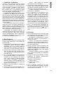
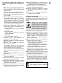
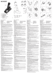
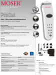
USB-AUDIO-INTERFACE
USB AUDIO INTERFACE
INTERFACE AUDIO USB
INTERFACCIA AUDIO USB
USB-SOUNDBOX Best.-Nr. 21.2200
BEDIENUNGSANLEITUNG • INSTRUCTION MANUAL
MODE D’EMPLOI • ISTRUZIONI PER L’USO
MANUAL DE INSTRUCCIONES • INSTRUKCJA OBSŁUGI
D
A
CH
Bevor Sie einschalten ...
F
Avant toute mise en service ...
B
Lisez ce mode d’emploi entièrement
avant toute utilisation. Uniquement
ainsi, vous pourrez apprendre l’ensemble des possibilités de fonctionnement de l’appareil, éviter toute manipulation erronée et vous protéger, ainsi
que l’appareil, de dommages éventuels engendrés par une utilisation
inadaptée. Conservez la notice pour
pouvoir vous y reporter ultérieurement.
La version française commence à la
page 10.
CH
E
GB
Bitte lesen Sie diese Bedienungsanleitung vor dem Betrieb gründlich
durch. Nur so lernen Sie alle
Funktionsmöglichkeiten kennen, vermeiden Fehlbedienungen und schützen sich und Ihr Gerät vor eventuellen Schäden durch unsachgemäßen
Gebrauch. Heben Sie die Anleitung
für ein späteres Nachlesen auf.
Der deutsche Text beginnt auf Seite 4.
Antes de cualquier instalación ...
Por favor, lea estas instrucciones de
uso atentamente antes de hacer funcionar el aparato. De esta manera
conocerá todas las funciones de la
unidad, se prevendrán errores de
operación, usted y el aparato estarán protegidos en contra de todo
daño causado por un uso inadecuado. Por favor, guarde las instrucciones para una futura utilización.
La versión española comienza en la
página 16.
Before you switch on ...
Please read these operating instructions carefully prior to operating the
unit. Thus, you will get to know all
functions of the unit, operating errors
will be prevented, and yourself and
the unit will be protected against any
damage caused by improper use.
Please keep the operating instructions for later use.
The English text starts on page 7.
I
Prima di accendere ...
Leggete attentamente le istruzioni
prima di mettere in funzione l’apparecchio. Solo così potete conoscere
tutte le funzionalità, evitare comandi
sbagliati e proteggere voi stessi e
l’apparecchio da eventuali danni in
seguito ad un uso improprio. Conservate le istruzioni per poterle consultare anche in futuro.
Il testo italiano comincia a pagina 13.
PL
Przed Uruchomieniem ...
Dzięki tej instrukcji obsługi będą
państwo w stanie poznać wszystkie
funkcje tego urządzenia. Stosując
się do instrukcji unikną państwo
błędów i ewentualnego uszkodzenia urządzenia na skutek nieprawidłowego użytkowania. Prosimy
zachować instrukcję.
Tekst polski znajduje się na stronie
19.
®
w w w.imgstageline.com
2
USB-SOUNDBOX USB AUDIO INTERFACE
INPUT FILTER
GAIN TRIM
SOURCE
SIGNAL/
CLIP
PHONO
LINE
LOW CUT
FLAT
1
2
–10
MONITOR
LEVEL
0
dB +10
3
S/PDIF IN
4
PC AUDIO OUT
POWER
PC
PRE
AMP MIX AUDIO
5
PREAMP OUT
6
ON
OFF / USB
10
7
PHONO IN
➀
8
LINE IN
GND
L
R
9 V /~
150 mA
S/PDIF OUT
9
10
11
12
13
14
15
16
➁
17
Blockschaltbild • Block diagram
PHONO IN
L
R
PREAMP OUT
L
GND
GAIN TRIM
RIAA
SIGNAL/
CLIP
SOURCE
PREAMP
LINE IN
L
INPUT
PHONO
FILTER
R
S /PDIF IN
PC AUDIO OUT
D
FLAT/
LOW CUT
MONITOR
MIX
A
LINE
R
LEVEL
USB
PC AUDIO OUT
D
A
L
R
S/PDIF OUT
➂
3
D
A
Bitte klappen Sie die Seite 3 heraus. Sie
sehen dann immer die beschriebenen Bedienelemente und Anschlüsse.
CH
1 Übersicht der Bedienelemente und
Anschlüsse
1 Eingangswahlschalter PHONO/LINE
2 Schalter zum Aktivieren des Hochpassfilters; bei gedrückter Taste ist das Filter aktiv
3 Regler GAIN TRIM zum Anpassen der Eingangsverstärkung (±10 dB)
4 LED SIGNAL/CLIP:
leuchtet grün, wenn ein analoges Eingangssignal vorhanden ist. Leuchtet sie rot, ist der
Eingang übersteuert. In diesem Fall den
Regler GAIN TRIM (3) zurückdrehen oder
den Ausgangspegel der Signalquelle reduzieren.
5 Schalter SOURCE zur Wahl der Signalquelle für den Kopfhörerausgang (6):
Position PREAMP:
vorverstärktes Signal des Eingangs
PHONO oder LINE
Position PC AUDIO:
über die USB-Verbindung kommendes
Audiosignal vom PC
Position MIX:
beide Signalquellen (PREAMP und
PC AUDIO) sind zu hören
6 3,5-mm-Klinkenbuchse MONITOR zum Anschluss eines Stereokopfhörers
7 Regler LEVEL zum Einstellen der Kopfhörerlautstärke
8 Schalter POWER zum Ein- und Ausschalten des Geräts; bei Verwendung des
Steckernetztrafos zum Einschalten die
Taste hineindrücken (die Taste leuchtet rot);
bei Versorgung des Interfaces über die
USB-Schnittstelle die Taste ausrasten (sie
leuchtet blau)
9 Schraubklemme als Masseanschluss für
einen Plattenspieler
10 USB-Buchse (Typ B) zum Anschluss eines
Computers
11 Cinch-Buchse S/PDIF IN zum Anschluss
einer Signalquelle mit Digitalausgang
12 Cinch-Buchse S/PDIF OUT; dieser Ausgang liefert ein vom angeschlossenen Computer kommendes digitales Audiosignal
13 Cinch-Buchsen PC AUDIO OUT; dieser Ausgang liefert ein vom angeschlossenen Computer kommendes analoges Stereosignal
4
14 Cinch-Buchsen PREAMP OUT; dieser Ausgang liefert das vorverstärkte Signal des
Eingangs PHONO IN (15) oder LINE IN (16)
15 Cinch-Buchsen PHONO IN; zum Anschluss
eines Plattenspielers mit Magnetsystem
16 Cinch-Buchsen LINE IN; zum Anschluss
einer Signalquelle mit Line-Pegel (z. B. CDSpieler)
17 Anschlussbuchse „9 V /~“ für den beiliegenden Steckertrafo zur Stromversorgung
2 Wichtige Hinweise zur Sicherheit
Die Geräte (USB-Audio-Interface und Steckertrafo) entsprechen allen erforderlichen Richtlinien
der EU und sind deshalb mit
gekennzeichnet.
WARNUNG
Der Steckertransformator wird
mit lebensgefährlicher Netzspannung (230 V~) versorgt.
Nehmen Sie deshalb niemals
selbst Eingriffe daran vor! Es
besteht die Gefahr eines elektrischen Schlages.
Beachten Sie auch unbedingt die folgenden
Punkte:
● Verwenden Sie die Geräte nur im Innenbereich
und schützen Sie sie vor Tropf- und Spritzwasser, hoher Luftfeuchtigkeit und Hitze (zulässiger Einsatztemperaturbereich 0 – 40 °C) .
● Nehmen Sie das Audio-Interface nicht in Be-
trieb und ziehen Sie sofort den Steckertrafo
aus der Steckdose, wenn:
1. sichtbare Schäden am Steckertrafo oder
am Audio-Interface vorhanden sind,
2. nach einem Sturz oder Ähnlichem der Verdacht auf einen Defekt besteht,
3. Funktionsstörungen auftreten.
Lassen Sie die Geräte in jedem Fall in einer
Fachwerkstatt reparieren.
● Verwenden Sie für die Reinigung nur ein
trockenes, weiches Tuch, auf keinen Fall
Chemikalien oder Wasser.
● Wird das Audio-Interface oder der Steckertrafo
zweckentfremdet, falsch angeschlossen, nicht
richtig bedient oder nicht fachgerecht repariert,
kann keine Haftung für daraus resultierende
Sach- oder Personenschäden und keine Garantie für die Geräte übernommen werden.
Sollen die Geräte endgültig aus dem
Betrieb genommen werden, übergeben Sie sie zur umweltgerechten Entsorgung einem örtlichen Recyclingbetrieb.
3 Verwendungsmöglichkeiten
Die USB-Soundbox ist primär als Audio-Schnittstelle zwischen Tonquellen, Aufnahmegeräten
und einem Computer mit USB 1.1- oder
USB 2.0-Anschluss konzipiert. Dadurch können
z. B. Schallplatten oder Musikkassetten auf
einen PC übertragen, dort bearbeitet und auf
CD gebrannt werden (wenn der Computer über
entsprechende Hard- und Software verfügt).
Das Gerät ist mit einem Phono-Eingang
zum Anschluss von Plattenspielern, einem Eingang für Signale mit Line-Pegel (z. B. CD-Spieler) sowie einem Eingang für digitale Audiosignale (S/PDIF = Sony/Philips digital interface
format) ausgestattet. Für die Analogeingänge
kann die Verstärkung angepasst und ein Hochpassfilter gegen tieffrequente Störungen eingeschaltet werden.
Die vom PC kommenden Audiosignale stehen als Analog- und Digitalsignale zur Verfügung. Zusätzlich gibt es Ausgänge für die vorverstärkten analogen Eingangssignale und
einen Kopfhörerausgang zur Kontrolle der Eingangssignale und der vom PC kommenden Audiosignale.
Die Stromversorgung des Geräts erfolgt
über die USB-Schnittstelle oder über den mitgelieferten Steckernetztrafo. Dadurch kann das
Gerät auch ohne einen Computer als eigenständiger Phono-Vorverstärker, Anpassverstärker für Line-Signale oder als Kopfhörerverstärker eingesetzt werden.
4 Gerät anschließen
Das Audio-Interface und die anzuschließenden
Audiogeräte ausschalten, bevor die Anschlüsse
hergestellt oder verändert werden.
1) Zum Anschluss eines Plattenspielers
mit Magnetsystem die Eingangsbuchsen
PHONO IN (15) verwenden. Ist am Anschlusskabel ein separates Massekabel vorhanden, dieses an der Masseschraube
GND (9) festklemmen.
2) Zum Anschluss einer Signalquelle mit LineAusgangspegel (z. B. CD-Spieler, Kassettenrekorder) die Eingangsbuchsen LINE IN
(16) verwenden.
3) Soll das vorverstärkte Signal von den Eingängen LINE IN oder PHONO IN aufgenommen oder über eine Lautsprecheranlage wiedergegeben werden, den Eingang
des nachfolgenden Gerätes (z. B. Verstärker, Aufnahmegerät, Mischpult) an die Buchsen PREAMP OUT (14) anschließen. Der
Eingang muss für Signale mit Line-Pegel
ausgelegt sein.
4) Den USB-Anschluss eines Computers mit
der USB-Buchse (10) verbinden.
5) Zum Anschluss eines digitalen Audiosignals
im S/PDIF-Format die Buchse S/PDIF IN
(11) verwenden.
Hinweis: Dieser Eingang ist nur in Verbindung mit einem Computer nutzbar.
6) Für die Verarbeitung eines digitalen Audiosignals im S/PDIF-Format den Eingang des
nachfolgenden Geräts (Digitalrekorder, Verstärker, Mischpult) an die Buchse
S/PDIF OUT (12) anschließen.
Hinweis: Dieser Ausgang ist nur in Verbindung mit einem Computer nutzbar.
7) Für die Verstärkung oder Aufnahme eines
vom Computer kommenden Audiosignals
den Eingang des nachfolgenden Geräts
(Aufnahmegerät, Verstärker, Mischpult) an
die Buchsen PC AUDIO OUT (13) anschließen. Der Eingang muss für Signale mit
Line-Pegel ausgelegt sein.
8) Zum Abhören der analogen Eingangssignale und der Signale vom PC einen Stereokopfhörer (empfohlene Impedanz ≥ 32 Ω) mit
3,5-mm-Klinkenstecker an die Buchse MONITOR (6) anschließen.
9) Für einen vom Computer unabhängigen Betrieb den Kleinspannungsstecker des beiliegenden Steckertrafos in die Buchse „9 V /~“
(17) stecken und den Trafo in eine Steckdose
(230 V~/ 50 Hz).
D
A
CH
5 Bedienung
1) Für eine Stromversorgung über den USBAnschluss (10) den Schalter POWER (8)
ausrasten. Der Schalter leuchtet blau.
Soll das Gerät über den mitgelieferten
Steckertrafo versorgt werden, den Schalter
hineindrücken; er leuchtet dann rot.
Hinweis: Treten im Betrieb Störgeräusche (z. B. Brummen) auf, ausprobieren, ob
sich diese durch die jeweils andere Stromversorgungsart minimieren lassen.
2) Sobald das Audio-Interface eingeschaltet
ist, werden seine Audio-Anschlüsse vom
Betriebssystem des angeschlossenen Computers als zwei USB-Audiogeräte (Toneingabe und -ausgabe) erkannt.
Bei Bedarf die vom Betriebssystem geforderten Gerätetreiber nachinstallieren und
den Computer neu starten.
3) Ist eine Signalquelle am Eingang PHONO IN
oder LINE IN angeschlossen, diese mit dem
Schalter INPUT (1) auswählen:
Schalter gedrückt (leuchtet):
PHONO-Eingang
5
D
A
4)
CH
5)
6)
7)
Schalter ausgerastet:
LINE-Eingang
Mit dem Schalter FILTER (2) können für die
Eingänge PHONO IN und LINE IN tieffrequente Störungen (z. B. Trittschall) ausgefiltert werden.
Schalter gedrückt (leuchtet):
Filter eingeschaltet (LOW CUT)
Schalter ausgerastet:
Filter ausgeschaltet (FLAT)
Mit dem Regler GAIN TRIM (3) die Eingangsverstärkung so hoch einstellen, dass
die LED SIGNAL/CLIP (4) grün leuchtet.
Leuchtet sie bei den lautesten Passagen rot,
den Regler entsprechend zurückdrehen.
Mit dem Schalter SOURCE (5) die gewünschte Signalquelle für den Kopfhörer
einstellen:
PREAMP
das vorverstärkte Signal des PHONOoder LINE-Eingangs
PC AUDIO
das vom Computer kommende Audiosignal; je nach Einstellung des Computers
bzw. der verwendeten Programme kann
dieses Signal auch die (u. U. mit Verzögerung zu hörenden) Eingangssignale enthalten
MIX
eine Mischung aus PREAMP-Signal und
PC-AUDIO-Signal
Mit dem Regler LEVEL (7) die gewünschte
Kopfhörerlautstärke einstellen.
6 Technische Daten
Frequenzbereich: . . . . . . . 5 – 20 000 Hz (+0/-3 dB)
Eingänge
Empfindlichkeit bei 1 V Ausgangsspannung
PHONO IN: . . . . . . . . . 1,7 – 22 mV
LINE IN: . . . . . . . . . . . 0,4 – 5,6 V
Impedanz
PHONO IN: . . . . . . . . . 47 kΩ
LINE IN: . . . . . . . . . . . 220 kΩ
S/PDIF IN
Auflösung: . . . . . . . . . . 16 Bit
Abtastraten: . . . . . . . . 32/44,1/48 kHz
Ausgänge
PREAMP OUT, PC AUDIO OUT
Nennpegel: . . . . . . . . . 1 V
Max. Pegel: . . . . . . . . . 1,2 V
Impedanz: . . . . . . . . . . 510 Ω
MONITOR: . . . . . . . . . . . max. 31 mW an 32 Ω
S/PDIF OUT
Auflösung: . . . . . . . . . . 16 Bit
Abtastrate: . . . . . . . . . 48 kHz
Hochpassfilter, schaltbar: . 23 Hz; 12 dB/Oktave
Stromversorgung: . . . . . . . 9 V~/150 mA über
beiliegenden Steckertrafo
an 230 V~/50 Hz/10 VA
oder über USB-Leitung
Abmessungen: . . . . . . . . . 156 mm × 120 mm × 50 mm
Gewicht ohne Netztrafo: . . 590 g
Geeignete Betriebssysteme:
Windows 98 SE, Windows ME, Windows 2000,
Windows XP, Mac OS 9, Mac OS X
VORSICHT Stellen Sie die Kopfhörerlautstärke nie sehr hoch ein.
Hohe Lautstärken können
auf Dauer das Gehör schädigen! Das Ohr gewöhnt sich
an große Lautstärken und
empfindet sie nach einiger
Zeit als nicht mehr so hoch.
Darum eine hohe Lautstärke
nach der Gewöhnung nicht
weiter erhöhen.
8) Nach dem Betrieb über den Steckertrafo
diesen aus der Steckdose ziehen, da er
auch bei ausgeschaltetem Gerät einen geringen Strom verbraucht.
Änderungen vorbehalten.
Windows ist ein registriertes Warenzeichen der Microsoft
Corporation in den USA und anderen Ländern. Mac OS ist
ein registriertes Warenzeichen von Apple Computer, Inc. in
den USA und anderen Ländern.
Diese Bedienungsanleitung ist urheberrechtlich für MONACOR ® INTERNATIONAL GmbH & Co. KG geschützt. Eine Reproduktion für eigene kommerzielle Zwecke – auch auszugsweise – ist untersagt.
6
Please unfold page 3. Then you can always
see the operating elements described.
1 Operating Elements and Connections
1 Input selector switch PHONO/LINE
2 Switch for activating the high pass filter; with
the button pressed, the filter is active
3 Control GAIN TRIM for adapting the input
amplification (±10 dB)
4 LED SIGNAL/CLIP:
shows green if an analog input signal is
present. If it shows red, the input is overloaded. In this case turn back the control
GAIN TRIM (3) or reduce the output level of
the signal source.
5 Switch SOURCE for selecting the signal
source for the headphone output (6):
position PREAMP:
preamplified signal of the input PHONO or
LINE
position PC AUDIO:
audio signal of the PC coming via the USB
connection
position MIX:
both signal sources (PREAMP and
PC AUDIO) can be heard
6 3.5 mm jack MONITOR for connection of
stereo headphones
7 Control LEVEL for adjusting the headphone
volume
8 Switch POWER for switching the unit on
and off; when using the plug-in mains transformer, press the button for switching on
(the button shows red); when supplying the
USB soundbox via the USB interface, disengage the button (it shows blue)
9 Screw terminal as a ground connection for a
turntable
10 USB jack (type B) for connection of a computer
11 Phono jack S/PDIF IN for connection of a
signal source with digital output
12 Phono jack S/PDIF OUT; this output supplies a digital audio signal coming from the
connected computer
13 Phono jacks PC AUDIO OUT; this output
supplies an analog stereo signal coming
from the connected computer
14 Phono jacks PREAMP OUT; this output
supplies the preamplified signal of the input
PHONO IN (15) or LINE IN (16)
15 Phono jacks PHONO IN; for connection of a
turntable with magnetic system
16 Phono jacks LINE IN; for connection of a
signal source with line level (e. g. CD player)
17 Connection jack “9 V /~” for the supplied
plug-in transformer for power supply
GB
2 Important Safety Notes
The units (USB audio interface and plug-in transformer) correspond to all required directives of
the EU and are therefore marked with
.
WARNING
The plug-in transformer is supplied with hazardous mains voltage (230 V~). Leave servicing
to skilled personnel only. Inexpert handling or modification of
the unit may cause an electric
shock hazard.
It is essential to observe the following items:
● The units are suitable for indoor use only. Protect them against dripping water and splash
water, high air humidity and heat (admissible
ambient temperature range 0 – 40 °C).
● Do not set the audio interface into operation,
or immediately disconnect the plug-in transformer from the mains socket if
1. there is visible damage to the plug-in transformer or to the audio interface,
2. a defect might have occurred after a drop
or similar accident,
3. malfunctions occur.
The units must in any case be repaired by
skilled personnel.
● For cleaning only use a dry, soft cloth, by no
means chemicals or water.
● No guarantee claims for the audio interface
or the plug-in transformer and no liability for
any resulting personal damage or material
damage will be accepted if the units are used
for other purposes than originally intended, if
they are not correctly connected, operated, or
not repaired in an expert way.
If the units are to be put out of operation definitively, take them to a local
recycling plant for a disposal which is
not harmful to the environment.
3 Applications
The USB soundbox is primarily designed as an
audio interface between audio sources, recorders, and a computer with USB 1.1 or USB 2.0
connection. Thus, e. g. records or music cassettes can be transmitted to a PC, processed there
7
GB
and burnt on CD (if the computer has a corresponding hardware and software).
The unit is equipped with a phono input for
connection of turntables, an input for signals
with line level (e. g. CD player) and an input for
digital audio signals (S/PDIF = Sony/Philips digital interface format). For the analog inputs the
amplification may be adapted and a high pass
filter may be switched on against low-frequency
interference.
The audio signals coming from the PC are
available as analog and digital signals. In addition, there are outputs for the preamplified analog input signals and a headphone output to
check the input signals and the audio signals
coming from the PC.
The power supply of the unit is made via the
USB interface or via the supplied plug-in mains
transformer. Thus, the unit can also be used
without a computer as an independent phono
preamplifier, as a matching amplifier for line signals, or as a headphone amplifier.
4 Connecting the Unit
Switch off the audio interface and the audio
units to be connected before making or changing the connections.
1) For connection of a turntable with magnetic
system use the input jacks PHONO IN (15).
If a separate ground cable is available at the
connection cable, fix it to the ground screw
GND (9).
2) For connection of a signal source with line
output level (e. g. CD player, cassette recorder) use the input jacks LINE IN (16).
3) If the preamplified signal is to be recorded
by the inputs LINE IN or PHONO IN or to be
reproduced via a speaker system, connect
the input of the following unit (e. g. amplifier,
recorder, mixer) to the jacks PREAMP OUT
(14). The input must be designed for signals
with line level.
4) Connect the USB connection of a computer
to the USB jack (10).
5) For connection of a digital audio signal in
S/PDIF format use the jack S/PDIF IN (11).
Note: This input can only be used in
connection with a computer.
6) For processing a digital audio signal in
S/PDIF format, connect the input of the following unit (digital recorder, amplifier, mixer)
to the jack S/PDIF OUT (12).
Note: This output can only be used in
connection with a computer.
8
7) For the amplification or recording of an
audio signal coming from the computer
connect the input of the following unit (recorder, amplifier, mixer) to the jacks
PC AUDIO OUT (13). The input must be designed for signals with line level.
8) To monitor the analog input signals and the
signals from the PC, connect stereo headphones (recommended impedance ≥ 32 Ω)
with 3.5 mm plug to the jack MONITOR (6).
9) For an operation independent of the computer connect the low voltage plug of the
supplied plug-in transformer to the jack
“9 V /~” (17) and the transformer to a
socket (230 V~/50 Hz).
5 Operation
1) For a power supply via the USB connection
(10) disengage the switch POWER (8). The
switch shows blue.
For supplying the unit with power via the
supplied plug-in transformer, press the
switch; then it shows red.
Note: If interfering noise (e. g. humming)
occurs during operation, test if these can be
minimized by the other type of power supply.
2) As soon as the audio interface is switched
on, its audio connections are recognized by
the operating system of the connected computer as two USB audio units (audio input
and audio output).
If necessary, install the drivers required
by the operating system and restart the
computer.
3) If a signal source is connected to the input
PHONO IN or LINE IN, select it with the
switch INPUT (1):
switch pressed (lights up):
PHONO input
switch disengaged:
LINE input
4) With the switch FILTER (2) the low-frequency interference (e. g. subsonic sound)
can be filtered out for the inputs PHONO IN
and LINE IN.
Switch pressed (lights up):
filter switched on (LOW CUT)
Switch disengaged:
filter switched off (FLAT)
5) With the control GAIN TRIM (3) adjust the
input amplification to such an extent that the
LED SIGNAL/CLIP (4) shows green. If it
shows red with the passages of the highest
volume, turn back the control correspondingly.
6) With the switch SOURCE (5) adjust the desired signal source for the headphones:
PREAMP
the preamplified signal of the PHONO or
LINE input
PC AUDIO
the audio signal coming from the computer; depending on the adjustment of the
computer or the programmes used, this
signal can also contain the input signals
(which are possibly heard with delay)
MIX
a mix of PREAMP signal and PC AUDIO
signal
7) Adjust the desired headphone volume with
the control LEVEL (7).
CAUTION
Never adjust the headphones
to a very high volume. Permanent high volumes may
damage your hearing! The
human ear will get accustomed to high volumes which
do not seem to be that high
any more after some time.
Therefore, do not further increase a high volume after
getting used to it.
8) After operation via the plug-in transformer,
disconnect it from the socket as it consumes
a low current even if the unit is switched off.
6 Specifications
GB
Frequency range: . . . . . . . 5 – 20 000 Hz (+0/-3 dB)
Inputs
sensitivity at 1 V output voltage
PHONO IN: . . . . . . . . . 1.7 – 22 mV
LINE IN: . . . . . . . . . . . 0.4 – 5.6 V
impedance
PHONO IN: . . . . . . . . . 47 kΩ
LINE IN: . . . . . . . . . . . 220 kΩ
S/PDIF IN
resolution: . . . . . . . . . . 16 bits
sampling rates: . . . . . . 32/44.1/48 kHz
Outputs
PREAMP OUT, PC AUDIO OUT
rated level: . . . . . . . . . 1 V
max. level: . . . . . . . . . . 1.2 V
impedance: . . . . . . . . . 510 Ω
MONITOR: . . . . . . . . . . . 31 mW max. at 32 Ω
S/PDIF OUT
resolution: . . . . . . . . . . 16 bits
sampling rate: . . . . . . . 48 kHz
High pass filter, switchable: 23 Hz; 12 dB/octave
Power supply: . . . . . . . . . . 9 V~/150 mA via supplied
plug-in transformer
connected to
230 V~/50 Hz/10 VA
or via USB cable
Dimensions: . . . . . . . . . . . 156 mm × 120 mm × 50 mm
Weight
w/o mains transformer: . . . 590 g
Suitable operating systems:
Windows 98 SE, Windows ME, Windows 2000,
Windows XP, Mac OS 9, Mac OS X
Subject to technical modification.
Windows is a registered trademark of the Microsoft Corporation in the USA and other countries. Mac OS is a registered
trademark of Apple Computer, Inc. in the USA and other
countries.
All rights reserved by MONACOR ® INTERNATIONAL GmbH & Co. KG. No part of this instruction manual
may be reproduced in any form or by any means for any commercial use.
9
F
Ouvrez le présent livret page 3 de manière à
visualiser les éléments et branchements.
B
CH
1 Eléments et branchements
1 Sélecteur d’entrée PHONO/LINE
2 Interrupteur pour activer le filtre passe-haut ;
le filtre est activé si la touche est enfoncée
3 Potentiomètre de réglage trimmer GAIN
TRIM pour adapter l’amplification d’entrée
(±10 dB)
4 LED SIGNAL/CLIP : brille en vert lorsqu’un
signal d’entrée analogique est présent. Si
elle brille en rouge, l’entrée est en surcharge.
Dans ce cas, tournez le réglage GAIN TRIM
(3) dans l’autre sens ou diminuez le niveau
de sortie de la source de signal.
5 Interrupteur SOURCE pour sélectionner la
source de signal pour la sortie casque (6) :
position PREAMP :
signal préamplifié de l’entrée PHONO ou
LINE
position PC AUDIO :
signal audio venant du PC via la liaison
USB
position MIX :
les deux sources de signal (PREAMP et
PC AUDIO) sont audibles
6 Prise jack 3,5 MONITOR pour brancher un
casque stéréo
7 Potentiomètre de réglage LEVEL pour régler le volume du casque
8 Interrupteur POWER pour allumer et éteindre l’appareil ; si vous utilisez le transfo secteur, enfoncez la touche pour allumer (la
touche brille en rouge) ; si vous utilisez l’alimentation de l’interface via l’interface USB,
désenclenchez la touche (elle brille en bleu).
9 Borne à vis pour le branchement masse
d’une platine disque
10 Prise USB (type B) pour brancher un ordinateur
11 Prise RCA S/PDIF IN pour brancher une
source de signal avec sortie digitale
12 Prise RCA S/PDIF OUT ; cette sortie délivre
un signal audio digital venant de l’ordinateur
relié
13 Prises RCA PC AUDIO OUT ; cette sortie
délivre un signal stéréo analogique venant
de l’ordinateur relié
14 Prises RCA PREAMP OUT : cette sortie délivre le signal préamplifié de l’entrée
PHONO IN (15) ou LINE IN (16)
15 Prises RCA PHONO IN : pour brancher une
platine disque avec système magnétique
10
16 Prises RCA LINE IN : pour brancher une
source de signal avec niveau ligne (par exemple lecteur CD)
17 Prise de branchement “9 V /~” pour le
transfo d’alimentation livré
2 Conseils d’utilisation et de sécurité
Les appareils (interface audio USB et transfo
secteur) répondent à toutes les directives nécessaires de l’Union Européenne et portent
donc le symbole
.
AVERTISSEMENT Le transfo secteur est alimenté par une tension
dangereuse (230 V~). Faites toujours appel à un
technicien spécialisé car,
en cas de mauvaise manipulation, vous pourriez
subir une décharge électrique.
Respectez scrupuleusement les points suivants :
● Les appareils ne sont conçus que pour une
utilisation en intérieur. Protégez-les de tout
type de projections d’eau, des éclaboussures, d’une humidité de l’air élevée et de la
chaleur (plage de température de fonctionnement autorisée : 0 – 40 °C).
● Ne faites jamais fonctionner l’interface audio
ou débranchez immédiatement le transfo
secteur lorsque :
1. des dommages visibles sur l’interface
audio ou le transfo apparaissent,
2. après une chute ou accident similaire,
vous avez un doute au sujet de l’état de
l’appareil.
3. des défaillances apparaissent.
Dans tous les cas, les dommages doivent
être réparés par un technicien spécialisé.
● Pour nettoyer les appareils, utilisez uniquement un chiffon sec et doux, en aucun cas de
produits chimiques ou d’eau.
● Nous déclinons toute responsabilité en cas
de dommages matériels ou corporels résultants si l’interface audio ou le transfo secteur
sont utilisés dans un but autre que celui pour
lequel ils ont été conçus, s’ils ne sont pas correctement branchés, utilisés ou réparés par
une personne habilitée ; en outre, la garantie
deviendrait caduque.
Lorsque les appareils sont définitivement retirés du service, vous devez
les déposer dans une usine de recyclage à proximité pour contribuer à
leur élimination non polluante.
3 Possibilités d’utilisation
L’interface audio USB est conçue en premier
lieu comme interface audio entre des sources
audio, des enregistreurs et un ordinateur avec
connexion USB 1.1 ou USB 2.0 ; ainsi, des disques, cassettes audio par exemple peuvent
être transférés sur un PC, travaillés et gravés
sur un CD (lorsqu’un ordinateur dispose des logiciels et hardware correspondants).
L’appareil est équipé d’une entrée phono
pour brancher des platines disques, d’une entrée pour signaux avec niveau ligne (par exemple lecteur CD) et d’une entrée pour signaux
audio digitaux (S/PDIF = Sony/Philips digital interface format). Pour les entrées analogiques,
l’amplification peut être réglée et un filtre passe
haut activé pour éliminer les perturbations à fréquences basses.
Les signaux audio venant du PC sont disponibles sous forme de signaux analogiques et
digitaux. De plus, il y a des sorties pour les signaux d’entrée analogiques préamplifiés et une
sortie casque pour contrôler les signaux d’entrée et les signaux audio venant du PC.
L’alimentation de l’appareil s’effectue via
l’interface USB ou via le bloc transfo livré. L’appareil peut ainsi être utilisé sans ordinateur
comme préamplificateur phono indépendant,
amplificateur d’adaptation pour signaux ligne
ou comme préamplificateur micro.
4 Branchements
Eteignez l’interface audio et les appareils audio
à relier avant d’effectuer ou de modifier les
branchements.
1) Pour brancher une platine disque à système
magnétique, utilisez les prises d’entrée
PHONO IN (15). Si un cordon masse distinct existe sur le cordon de branchement,
reliez celui-ci à la borne de masse GND (9).
2) Pour brancher une source de signal avec niveau de sortie ligne (par exemple lecteur
CD, magnétophone), utilisez les prises d’entrée LINE IN (16).
3) Si le signal préamplifié doit être enregistré
par les entrées LINE IN ou PHONO IN, ou
reproduit via une installation de haut-parleurs, reliez l’entrée de l’appareil suivant
(par exemple amplificateur, enregistreur,
table de mixage) aux prises PREAMP OUT
(14). L’entrée doit être configurée pour des
signaux avec niveau ligne.
4) Reliez la connexion USB d’un ordinateur à
la prise USB (10).
5) Pour brancher un signal audio digital au format S/PDIF, utilisez la prise S/PDIF IN (11).
6)
7)
8)
9)
Conseil : cette entrée n’est utilisable
qu’en liaison avec un ordinateur.
Pour traiter un signal audio digital au format
S/PDIF, reliez l’entrée de l’appareil suivant
(enregistreur numérique, amplificateur, table
de mixage) à la prise S/PDIF OUT (12).
Conseil : cette sortie n’est utilisable qu’en
liaison avec un ordinateur.
Pour l’amplification ou l’enregistrement d’un
signal audio venant de l’ordinateur, reliez
l’entrée de l’appareil suivant (enregistreur,
amplificateur, table de mixage) aux prises
PC AUDIO OUT (13). L’entrée doit être configurée pour des signaux avec niveau ligne.
Pour écouter les signaux d’entrée analogiques et les signaux du PC, reliez un casque
stéréo (impédance recommandée ≥ 32 Ω)
avec fiche jack 3,5 à la prise MONITOR (6).
Pour un fonctionnement indépendant de
l’ordinateur, reliez la fiche d’alimentation du
bloc secteur livré à la prise “9 V /~” (17) et
reliez le transfo à une prise secteur 230 V~/
50 Hz.
F
B
CH
5 Utilisation
1) Pour une alimentation via la connexion USB
(10), désenclenchez l’interrupteur POWER
(8), l’interrupteur s’allume en bleu.
Si l’appareil est alimenté par le transfo
secteur livré, appuyez sur l’interrupteur, il
s’allume en rouge.
Conseil : en cas de bruits perturbateurs
(ronflements par exemple) pendant le fonctionnement, essayez de les réduire par l’autre mode d’alimentation.
2) Dès que l’interface audio est allumée, ses
connexions audio sont reconnues par le
système d’exploitation de l’ordinateur relié
comme deux appareils audio USB (entrée
audio et sortie audio).
Si besoin, installez les drivers demandés
par le système d’exploitation et redémarrez
l’ordinateur.
3) Si une source de signal est reliée à l’entrée
PHONO IN ou LINE IN, sélectionnez-la
avec l’interrupteur INPUT (1) :
interrupteur enfoncé (brille) :
entrée PHONO
interrupteur non enfoncé :
entrée LINE
4) Avec l’interrupteur FILTER (2), les interférences de fréquences basses (p. ex. bruits
de pas) peuvent être filtrées pour les entrées PHONO IN et LINE IN.
11
F
B
CH
interrupteur enfoncé (brille) :
filtre activé (LOW CUT)
interrupteur non enfoncé :
filtre désactivé (FLAT)
5) Avec le réglage GAIN TRIM (3), réglez l’amplification d’entrée suffisamment élevée de
telle sorte que la LED SIGNAL/CLIP (4)
brille en vert. Si elle brille en rouge pour des
passages plus élevés, tournez le réglage
dans l’autre sens pour diminuer.
6) Avec l’interrupteur SOURCE (5), réglez la
source de signal voulue pour le casque :
PREAMP :
le signal préamplifié de l’entrée PHONO
ou LINE
PC AUDIO :
le signal audio venant de l’ordinateur.
Selon le réglage de l’ordinateur ou des programmes utilisés, ce signal peut contenir
également les signaux d’entrée (il est possible de les écouter avec temporisation).
MIX :
un mixage du signal PREAMP et du signal
PC AUDIO
7) Avec le réglage LEVEL (7), réglez le volume
souhaité du casque.
PRECAUTION Ne réglez jamais le volume du casque trop fort.
Des volumes extrêmement
élevés peuvent endommager l’ouïe. L’oreille humaine s’habitue à des volumes élevés et, après un
certain temps, ne les
perçoit plus de la même
manière. C’est pourquoi
vous ne devez pas augmenter le volume une fois
que vous y êtes habitué.
8) Après le fonctionnement, débranchez le
transfo du secteur car il a une faible consommation même si l’appareil est éteint.
6 Caractéristiques techniques
Bande passante : . . . . . . . 5 – 20 000 Hz (+0/-3 dB)
Entrées
Sensibilité pour tension de sortie 1 V
PHONO IN : . . . . . . . . 1,7 – 22 mV
LINE IN : . . . . . . . . . . . 0,4 – 5,6 V
Impédance
PHONO IN : . . . . . . . . 47 kΩ
LINE IN : . . . . . . . . . . . 220 kΩ
S/PDIF IN
Résolution : . . . . . . . . . 16 Bit
Taux sampling : . . . . . . 32/44,1/48 kHz
Sorties
PREAMP OUT, PC AUDIO OUT
Niveau nominal : . . . . . 1 V
Niveau maximal : . . . . 1,2 V
Impédance : . . . . . . . . 510 Ω
MONITOR : . . . . . . . . . . 31 mW max. sous 32 Ω
S/PDIF OUT
Résolution : . . . . . . . . . 16 Bit
Taux sampling : . . . . . . 48 kHz
Filtre passe-haut,
commutable : . . . . . . . . . . 23 Hz; 12 dB/octave
Alimentation : . . . . . . . . . . 9 V~/150 mA par transfo
secteur livré relié à
230 V~/50 Hz/10 VA
ou par connexion USB
Dimensions : . . . . . . . . . . 156 mm × 120 mm × 50 mm
Poids sans transfo : . . . . . 590 g
Système d’exploitation nécessaire :
Windows 98 SE, Windows ME, Windows 2000,
Windows XP, Mac OS 9, Mac OS X
Tout droit de modification réservé.
Windows est une marque déposée de la société Microsoft
Corporation aux Etats-Unis et dans les autres pays. Mac OS
est une marque déposée de la société Apple Computer, Inc.
aux Etats-Unis et dans les autres pays.
Notice d’utilisation protégée par le copyright de MONACOR ® INTERNATIONAL GmbH & Co. KG. Toute
reproduction même partielle à des fins commerciales est interdite.
12
Vi preghiamo di aprire completamente la pagina 3. Così vedrete sempre gli elementi di
comando e i collegamenti descritti.
1 Elementi di comando e collegamenti
1 Selettore d’ingresso PHONO/LINE
2 Interruttore per attivare il filtro passa-alto;
con il tasto premuto, il filtro è attivo
3 Regolatore GAIN TRIM per adattare l’amplificazione all’ingresso (±10 dB)
4 LED SIGNAL/CLIP:
si accende di color verde, se è presente un
segnale analogico d’ingresso. Se si accende di color rosso, l’ingresso è sovrapilotato.
In questo caso abbassare il regolatore
GAIN TRIM (3) oppure ridurre il livello
d’uscita della sorgente.
5 Selettore SOURCE per scegliere la sorgente per l’uscita cuffia (6):
Posizione PREAMP:
segnale preamplificato dell’ingresso
PHONO o LINE
Posizione PC AUDIO:
segnale audio del PC che arriva attraverso la porta USB
Posizione MIX:
si sentono entrambe le sorgenti (PREAMP
e PC AUDIO)
6 Presa jack 3,5 mm MONITOR per il collegamento di una cuffia stereo
7 Regolatore LEVEL per impostare il volume
della cuffia
8 Interruttore POWER per accendere e spegnere l’apparecchio; usando il trasformatore a spina, premere il tasto per accendere
(il tasto si accende di color rosso); in caso di
alimentazione dell’interfaccia tramite la
porta USB, sbloccare il tasto (si accende di
colore blu)
9 Morsetto a vite per la massa di un giradischi
10 Presa USB (tipo B) per il collegamento di un
computer
11 Presa RCA S/PDIF IN per il collegamento
di una sorgente di segnali con uscita digitale
12 Presa RCA S/PDIF OUT; questa uscita
fornisce un segnale audio digitale proveniente dal computer collegato
13 Prese RCA PC AUDIO OUT; questa uscita
fornisce un segnale audio analogico stereo
proveniente dal computer collegato
14 Prese RCA PREAMP OUT; questa uscita
fornisce il segnale preamplificato dell’ingresso PHONO IN (15) o LINE IN (16)
15 Prese RCA PHONO IN; per il collegamento
di un giradischi con sistema magnetico
I
16 Prese RCA LINE IN; per il collegamento di
una sorgente con livello di linea (p. es. lettore CD)
17 Presa di contatto “9 V /~” per il trasformatore a spina in dotazione, per l’alimentazione
2 Avvertenze di sicurezza
Gli apparecchi (interfaccia audio USB e trasformatore a spina) sono conformi a tutte le direttive
richieste dell’UE e pertanto portano la sigla
.
AVVERTIMENTO Il trasformatore a spina
funziona con pericolosa
tensione di rete (230 V~).
Non intervenire mai personalmente al suo interno!
Esiste il pericolo di una
scarica elettrica pericolosa.
Si devono osservare assolutamente anche i seguenti punti:
● Far funzionare gli apparecchi solo all’interno
di locali e proteggerli dall’acqua gocciolante e
dagli spruzzi d’acqua, da alta umidità dell’aria
e dal calore (temperatura d’impiego ammessa fra 0 e 40 °C).
● Non mettere in funzione l’interfaccia audio e
staccare subito il trasformatore dalla presa di
rete se:
1. il trasformatore o l’interfaccia audio presentano dei danni visibili;
2. dopo una caduta o dopo eventi simili sussiste il sospetto di un difetto;
3. gli apparecchi non funzionano correttamente.
Per la riparazione rivolgersi sempre ad un’officina competente.
● Per la pulizia usare solo un panno morbido,
asciutto; non impiegare in nessun caso prodotti chimici o acqua.
● Nel caso d’uso improprio, di collegamenti
sbagliati, d’impiego scorretto o di riparazione
non a regola d’arte dell’interfaccia audio o del
trasformatore, non si assume nessuna responsabilità per eventuali danni consequenziali a persone o a cose e non si assume nessuna garanzia per gli apparecchi.
Se si desidera eliminare gli apparecchi definitivamente, consegnarli
per lo smaltimento ad un’istituzione
locale per il riciclaggio.
13
I
3 Possibilità d’impiego
La USB-Soundbox è stata realizzata in primo
luogo come interfaccia audio fra sorgenti audio,
registratori e un computer con porta USB 1.1 o
USB 2.0. In questo modo è possibile trasferire
p. es. dischi o musicassette su un PC, elaborarli
e masterizzarli su un CD (se il computer dispone del necessario software e hardware).
L’apparecchio è equipaggiato con un ingresso Phono per il collegamento di giradischi,
con un ingresso per segnali con livello di linea
(p. es. lettore CD) nonché con un ingresso per
segnali digitali d’ingresso (S/PDIF = Sony/Philips digital interface format). Per gli ingressi
analogici, il guadagno può essere adattato e si
può inserire un filtro passa-alto contro le interferenze a bassa frequenza.
I segnali audio provenienti dal PC sono disponibili come segnali analogici e digitali. In più
ci sono delle uscite per i segnali analogici preamplificati d’ingresso e un’uscita per cuffia per il
controllo dei segnali d’ingresso e dei segnali
audio provenienti dal PC.
L’alimentazione dell’apparecchio avviene attraverso l’interfaccia USB oppure tramite un
trasformatore a spina in dotazione. Così, l’apparecchio può essere usato anche senza computer come preamplificatore phono autonomo,
come amplificatore d’adattamento per segnali
di linea o come amplificatore per cuffia.
5) Per il collegamento di un segnale audio digitale nel formato S/PDIF, usare la presa
S/PDIF IN (11).
N.B.: Questo ingresso può essere usato
solo in collegamento con un computer.
6) Per l’elaborazione di un segnale audio digitale nel formato S/PDIF, collegare l’ingresso
dell’apparecchio a valle (registratore digitale, amplificatore, mixer) con la presa
S/PDIF OUT (12).
N.B.: Questa uscita può essere usata solo
in collegamento con un computer.
7) Per l’amplificazione o per la registrazione di
un segnale audio proveniente dal computer,
collegare l’ingresso dell’apparecchio a valle
(registratore, amplificatore, mixer) con le
prese PC AUDIO OUT (13). L’ingresso deve
essere previsto per segnali con livello di
linea.
8) Per ascoltare il segnali analogici d’ingresso
e i segnali provenienti dal PC, collegare una
cuffia (impedenza consigliata ≥ 32 Ω) alla
presa MONITOR (6) usando un jack 3,5 mm.
9) Per il funzionamento non dipendente dal
computer, inserire lo spinotto per alimentazione DC del trasformatore a spina in dotazione nella presa “9 V /~” (17) e inserire il
trasformatore in una presa di rete (230 V~/
50 Hz).
5 Funzionamento
4 Collegare gli apparecchi
Spegnere l’interfaccia audio e gli apparecchi da
collegare prima di effettuare o modificare i collegamenti.
1) Per collegare un giradischi con sistema magnetico, usare le prese d’ingresso PHONO
IN (15). Se il cavo di collegamento possiede
un cavo separato per la massa, collegarlo
con la vite di massa GND (9).
2) Per collegare una sorgente con livello di
linea (p. es. lettore CD, registratore a cassette), usare le prese d’ingresso LINE IN
(16).
3) Se si vuole registrare o riprodurre attraverso
l’impianto di altoparlanti il segnale preamplificato degli ingressi LINE IN o PHONO IN,
collegare l’ingresso dell’apparecchio a valle
(p. es. amplificatore, registratore, mixer) con
le prese PREAMP OUT (14). L’ingresso
deve essere previsto per segnali con livello
di linea.
4) Collegare la porta USB del computer con la
presa USB (10).
14
1) Per l’alimentazione attraverso la porta USB
(10), sbloccare l’interruttore POWER (8).
L’interruttore si accende di colore blu.
Se l’apparecchio deve essere alimentato
con il trasformatore in dotazione, premere
l’interruttore che si accenderà di coloro rosso.
N.B.: Se durante il funzionamento si notano delle interferenze (p. es. ronzio), provare se si possono eliminare cambiando il
sistema di alimentazione.
2) Quando l’interfaccia audio è accesa, i suoi
contatti audio vengono riconosciuti dal sistema operativo del computer collegato
come due dispositivi USB (input e output
audio).
Se necessario, installare i driver richiesti
dal sistema operativo e riavviare il computer.
3) Se all’ingresso PHONO IN o LINE IN è collegato una sorgente, selezionarla con il selettore INPUT (1):
interruttore premuto (luce accesa):
ingresso PHONO
interruttore sbloccato:
ingresso LINE
4) Con l’interruttore FILTER (2) si possono eliminare interferenze a bassa frequenza
(p. es. da calpestio) per gli ingressi PHONO
IN e LINE IN.
interruttore premuto (luce accesa):
filtro attivato (LOW CUT)
interruttore sbloccato:
filtro disattivato (FLAT)
5) Con il regolatore GAIN TRIM (3) impostare
l’amplificazione dell’ingresso così forte che il
LED SIGNAL/CLIP (4) si accende di color
verde. Se con i brani più forti si accende di
color rosso, occorre abbassare il regolatore
in corrispondenza.
6) Con il selettore SOURCE (5) impostare la
sorgente desiderata per la cuffia:
PREAMP
il segnale preamplificato dell’ingresso
PHONO o LINE
PC AUDIO
il segnale audio proveniente dal computer; a seconda delle impostazioni del computer o dei programmi usati, tale segnale
può contenere anche i segnali d’ingresso
(da sentire eventualmente con ritardo)
MIX
un mix fra segnale PREAMP e segnale
PC-AUDIO
7) Con il regolatore LEVEL (7) impostare il volume desiderato per la cuffia.
ATTENZIONE Mai tenere molto alto il volume nelle cuffie. A lungo
andare, il volume eccessivo può procurare danni
all’udito! L’orecchio si abitua agli alti volumi e dopo
un certo tempo non se ne
rende più conto. Non aumentare il volume successivamente.
8) Dopo il funzionamento con il trasformatore a
spina staccare quest’ultimo dalla presa,
dato che consuma un po’ di corrente anche
se l’apparecchio è spento.
6 Dati tecnici
I
Gamma di frequenze: . . . . 5 – 20 000 Hz (+0/-3 dB)
Ingressi
Sensibilità con 1 V di tensione d’uscita
PHONO IN: . . . . . . . . . 1,7 – 22 mV
LINE IN: . . . . . . . . . . . 0,4 – 5,6 V
Impedenza
PHONO IN: . . . . . . . . . 47 kΩ
LINE IN: . . . . . . . . . . . 220 kΩ
S/PDIF IN
Risoluzione: . . . . . . . . 16 Bit
Campionatura: . . . . . . 32/44,1/48 kHz
Uscite
PREAMP OUT, PC AUDIO OUT
Livello nominale: . . . . . 1 V
Livello max.: . . . . . . . . 1,2 V
Impedenza: . . . . . . . . . 510 Ω
MONITOR: . . . . . . . . . . . max. 31 mW con 32 Ω
S/PDIF OUT
Risoluzione: . . . . . . . . 16 Bit
Campionatura: . . . . . . 48 kHz
Passa-alto, commutabile: . 23 Hz; 12 dB/ottava
Alimentazione: . . . . . . . . . 9 V~ /150 mA tramite
trasformatore a spina in
dotazione
con 230 V~/50 Hz/10 VA
oppure tramite linea USB
Dimensioni: . . . . . . . . . . . 156 mm × 120 mm × 50 mm
Peso senza trasformatore: 590 g
Sistemi operative adatti:
Windows 98 SE, Windows ME, Windows 2000,
Windows XP, Mac OS 9, Mac OS X
Con riserva di modifiche tecniche.
Windows è un marchio registrato della Microsoft Corporation
negli USA e un altri paesi. Mac OS è un marchio registrato
della Apple Computer, Inc. negli USA e in altri paesi.
La MONACOR ® INTERNATIONAL GmbH & Co. KG si riserva ogni diritto di elaborazione in qualsiasi forma
delle presenti istruzioni per l’uso. La riproduzione – anche parziale – per propri scopi commerciali è vietata.
15
E
Por favor, tome la página 3. A continuación podrá ver los elementos operativos
y las conexiones descritas.
1 Elementos operativos y conexiones
1 Interruptor selector de entrada PHONO/
LINE
2 Interruptor para activar el filtro pasa alto;
con el botón presionado, el filtro está activo
3 Control GAIN TRIM para adaptar la amplificación de entrada (±10 dB)
4 LED SIGNAL/CLIP:
aparece en verde si hay una señal de entrada analógica. Si aparece en rojo, la entrada está sobrecargada. En ese caso tire
hacia atrás el control GAIN TRIM (3) o reduzca el nivel de salida de la fuente de señal.
5 Interruptor SOURCE para seleccionar la fuente de señal para la salida de auricular (6):
posición PREAMP:
señal preamplificada de la entrada PHONO
o LINE
posición PC AUDIO:
señal audio del PC proveniente mediante
la conexión USB
posición MIX:
se pueden oír las dos fuentes de señal
(PREAMP y PC AUDIO)
6 jack 3,5 mm MONITOR para la conexión de
auriculares estéreo
7 Control LEVEL para ajustar el volumen de
auricular
8 Interruptor POWER para encender y apagar la unidad; cuando use el alimentador,
presione el botón para encender (el botón
aparece en rojo); cuando alimente la
SOUNDBOX USB mediante la interfaz
USB, suelte el botón (aparece en azul)
9 Terminal de tornillo como conexión de masa
para tocadiscos
10 Jack USB (tipo B) para conexión de un ordenador
11 Jack phono S/PDIF IN para conexión de
una fuente de señal con salida digital
12 Jack phono S/PDIF OUT; esta salida proporciona una señal audio digital proveniente del ordenador conectado
13 Jacks phono PC AUDIO OUT; esta salida
proporciona una señal estéreo analógica
proveniente del ordenador conectado
14 Jacks phono PREAMP OUT; esta salida
proporciona la señal preamplificada de la
entrada PHONO IN (15) o LINE IN (16)
16
15 Jacks phono PHONO IN; para conexión de
un tocadiscos con sistema magnético
16 Jacks phono LINE IN; para conexión de una
fuente de señal con nivel de línea (p. ej.
reproductor CD)
17 Jack de conexión “9 V /~” para el alimentador entregado para alimentación
2 Notas de seguridad importantes
Las unidades (interfaz audio USB y alimentador) corresponden a todas las Directivas requeridas por la UE y por ello están marcadas con
.
ADVERTENCIA El alimentador se alimenta
con un voltaje de red peligroso (230 V~). Deje el mantenimiento sólo en manos de
personal especializado. La
manipulación inexperta o la
modificación de la unidad
pueden causar un peligro de
descarga eléctrica.
Es esencial que tenga en cuenta los puntos siguientes:
● Las unidades sólo están indicadas para un
uso en interior. Protéjalas de goteos y salpicaduras de agua, humedad elevada del aire,
y calor (rango de temperatura ambiente admisible: 0 – 40 °C).
● No haga funcionar la interfaz audio, o desconecte el alimentador de la toma de red inmediatamente:
1. en caso de daño visible en el alimentador
o en la interfaz audio,
2. si ha ocurrido un defecto tras una caída o
un accidente similar,
3. si ocurren disfunciones.
Las unidades deben ser reparadas por personal especializado en cualquier caso.
● Para limpiar utilice sólo un paño seco y
suave, no utilice productos químicos o agua.
● No se asumirá ninguna garantía para la interfaz audio o el alimentador ni se aceptará ninguna responsabilidad en caso de daños personales o patrimoniales resultantes si las
unidades se usan para otros fines distintos a
los originalmente concebidos, si no están
correctamente conectadas o utilizadas, o si
no se reparan de manera experta.
Si las unidades se deben retirar del
funcionamiento
definitivamente,
llévelas a un centro de reciclaje local
para su disposición no contaminante
para el medio ambiente.
3 Aplicaciones
La SOUNDBOX USB ha sido diseñada principalmente como una interfaz audio entre fuentes
audio, grabadores, y un ordenador con conexión USB 1.1 o USB 2.0. De este modo se pueden transmitir p. ej. discos o cassettes de música a un PC, procesados ahí y grabados en
CD (si el ordenador tiene un hardware y software correspondiente).
La unidad está equipada con una entrada
phono para la conexión de tocadiscos, una entrada para señales con nivel de línea (p. ej. reproductor CD) y una entrada para señales
audio digitales (S/PDIF = formato interfaz digital Sony/Philips). Para las entradas analógicas
la amplificación se puede adaptar y se puede
encender un filtro pasa alto contra interferencias de frecuencias bajas.
Las señales audio provenientes del PC
están disponibles como señales analógicas y
digitales. Además, hay salidas para las señales
de entrada analógicas preamplificadas y una
salida de auricular para comprobar las señales
de entrada y las señales audio provenientes del
PC.
La alimentación de la unidad se hace mediante la interfaz USB o mediante el alimentador
entregado. De este modo, la unidad también se
puede usar sin un ordenador como un preamplificador phono independiente, amplificador
adecuado para señales de línea, o como amplificador de auricular.
4 Conexión de la unidad
Apague la interfaz audio y las unidades audio
que deban conectarse antes de hacer o cambiar las conexiones.
1) Para la conexión de un tocadiscos con sistema magnético use los jacks de entrada
PHONO IN (15). Si hay disponible un cable
de masa separado en el cable de conexión,
fíjelo en el tornillo de masa GND (9).
2) Para la conexión de una fuente de señal con
nivel de salida de línea (p. ej. reproductor
CD, grabador cassette) use los jacks de entrada LINE IN (16).
3) Si la señal preamplificada debe grabarse
mediante las entradas LINE IN o PHONO IN
o ser reproducidas mediante un sistema altavoz, conecte la entrada de la unidad siguiente (p. ej. amplificador, grabador, mezclador) a los jacks PREAMP OUT (14). La
entrada debe estar diseñada para señales
con nivel de línea.
4) Conecte la conexión USB para un ordenador al jack USB (10).
5) Para la conexión de una señal audio digital
en el formato S/PDIF use el jack S/PDIF IN
(11).
Nota: Esta entrada sólo se puede usar
en conexión con un ordenador.
6) Para procesar una señal audio digital en el
formato S/PDIF, conecte la entrada de la
unidad siguiente (grabador digital, amplificador, mezclador) al jack S/PDIF OUT (12).
Nota: Esta salida sólo se puede usar en
conexión con un ordenador.
7) Para la amplificación o grabación de una
señal audio proveniente desde el ordenador
conecte la entrada de la unidad siguiente
(grabador, amplificador, mezclador) a los
jacks PC AUDIO OUT (13). La entrada debe
estar diseñada para señales con nivel de
línea.
8) Para monitorizar las señales de entrada
analógicas y las señales desde el PC,
conecte auriculares estéreo (impedancia recomendada ≥ 32 Ω) con toma 3,5 mm al jack
MONITOR (6).
9) Para un funcionamiento independiente del
ordenador conecte la toma de bajo voltaje
del alimentador entregado al jack “9 V /~”
(17) y el transformador en una toma
(230 V~/50 Hz).
E
5 Funcionamiento
1) Para una alimentación mediante la conexión
USB (10) suelte el interruptor POWER (8).
El interruptor aparece en azul.
Para alimentar la unidad mediante el alimentador integrado, presione el interruptor;
a continuación aparece en rojo.
Nota: Si aparece ruido de interferencia
(p. ej. zumbido) durante el funcionamiento,
compruebe si se puede reducir con el otro
tipo de alimentación.
2) Tan pronto como la interfaz audio esté encendida, sus conexiones audio son reconocidas por el sistema operativo del ordenador
conectado como dos unidades audio USB
(entrada audio y salida audio).
Si es necesario, instale los drivers requeridos por el sistema operativo y reinicie el ordenador.
3) Si se conecta una fuente de señal a la entrada PHONO IN o LINE IN, selecciónela
con el interruptor INPUT (1):
interruptor presionado (se ilumina):
entrada PHONO
interruptor sin presionar:
entrada LINE
17
E
4) Con el interruptor FILTER (2) la interferencia
de frecuencias bajas (p. ej. sonido subsónico) se puede filtrar hacia fuera para las
entradas PHONO IN y LINE IN.
Interruptor presionado (se ilumina):
filtro encendido (LOW CUT)
Interruptor sin presionar:
filtro apagado (FLAT)
5) Con el control GAIN TRIM (3) ajuste la amplificación de entrada suficientemente alta
para que el LED SIGNAL/CLIP (4) aparezca
en verde. Si aparece en rojo con los pasajes
del volumen superior, gire hacia atrás el
control de manera correspondiente.
6) Con el interruptor SOURCE (5) ajuste la
fuente de señal deseada para los auriculares:
PREAMP
La señal preamplificada de la entrada
PHONO o LINE
PC AUDIO
La señal audio proveniente del ordenador; dependiendo del ajuste del ordenador o los programas usados esta señal
también puede contener las señales de
entrada (que posiblemente se oyen con
retraso)
MIX
una mezcla de señal PREAMP y señal
PC AUDIO
7) Ajuste el volumen de auricular deseado con
el control LEVEL (7).
PRECAUCIÓN No ajuste nunca un volumen muy alto. ¡Los volúmenes permanentemente
altos pueden dañar su
oído! El oído humano se
acostumbrará a los volúmenes altos que no parecerán tan altos al cabo
de un tiempo. Por lo tanto,
no aumente un volumen
alto tras haberse acostumbrado a él.
8) Tras el funcionamiento mediante el alimentador, desconéctelo de la toma porque tendrá un pequeño consumo incluso si la
unidad está apagada.
6 Características técnicas
Gama de frecuencia: . . . . 5 – 20 000 Hz (+0/- dB)
Entradas
sensibilidad a 1 V de voltaje de salida
PHONO IN: . . . . . . . . . 1,7 – 22 mV
LINE IN: . . . . . . . . . . . 0,4 – 5,6 V
impedancia
PHONO IN: . . . . . . . . . 47 kΩ
LINE IN: . . . . . . . . . . . 220 kΩ
S/PDIF IN
resolución: . . . . . . . . . 16 bits
índices de muestreo: . 32/44,1/48 kHz
Salidas
PREAMP OUT, PC AUDIO OUT
nivel considerado: . . . . 1 V
nivel máx.: . . . . . . . . . . 1,2 V
impedancia: . . . . . . . . 510 Ω
MONITOR: . . . . . . . . . . . 31 mW máx. a 32 Ω
S/PDIF OUT
resolución: . . . . . . . . . 16 bits
índice de muestreo: . . 48 kHz
Filtro pasa alto, conmutable: 23 Hz; 12 dB/octava
Alimentación: . . . . . . . . . . 9 V~/150 mA mediante alimentador entregado conectado a 230 V~/50 Hz/10 VA
o mediante cable USB
Dimensiones: . . . . . . . . . . 156 mm × 120 mm × 50 mm
Peso sin transformador
de red: . . . . . . . . . . . . . . . 590 g
Sistemas operativos indicados:
Windows 98 SE, Windows ME, Windows 2000,
Windows XP, Mac OS 9, Mac OS X
Sujeto a modificaciones técnicas.
Windows es una marca registrada de Microsoft Corporation
en los EEUU y otros países. Mac OS es una marca registrada de Apple Computer, Inc. en los EEUU y otros países.
Manual de instrucciones protegido por el copyright de MONACOR ® INTERNATIONAL GmbH & Co. KG.
Toda reproducción mismo parcial con fines comerciales está prohibida.
18
Na stronie 3 znajdują się schematy elementów sterujących i gniazd połączeniowych.
1 Elementy operacyjne i połączenia
1 Przełącznik wyboru sygnału wejściowego
PHONO/LINE
2 Włącznik filtra górnoprzepustowego; filtr
jest włączony przy wciśniętym przycisku
3 Pokrętło GAIN TRIM do regulacji wzmocnienia (±10 dB)
4 Dioda sygnalizacyjna LED SIGNAL/CLIP
Jeżeli dioda świeci na zielono – sygnał wejściowy ma odpowiedni poziom, jeśli
zaczyna świecić na czerwono – sygnał jest
przesterowany. W takiej sytuacji należy
skręcić regulator GAIN TRIM (3) lub zmniejszyć poziom głośności źródła sygnału.
5 Przełącznik SOURCE do wyboru źródła
sygnału dla wyjścia słuchawkowego (6):
pozycja PREAMP:
wzmocniony sygnał z wejścia PHONO
lub LINE
pozycja PC AUDIO:
sygnał audio z komputera przesyłany
przez złącze USB
pozycja MIX:
oba sygnały będą słyszalne
6 Gniazdo 3,5 mm jack MONITOR do
podłączania słuchawek stereo
7 Regulator LEVEL do ustawiania głośności
w słuchawkach
8 Włącznik sieci POWER do włączania/
wyłączania urządzenia;
w przypadku zasilania z sieci (zasilacz),
wcisnąć przycisk w celu włączenia urządzenia (włącznik świeci na czerwono)
przy zasilaniu poprzez interfejs USB należy
zwolnić przycisk (włącznik świeci na niebiesko)
9 Terminal śrubowy do podłączenia masy dla
gramofonu
10 Gniazdo USB (typ B) do podłączania
sygnału z komputera
11 Gniazdo S/PDIF IN do podłączania źródeł
dźwięku z wyjściami cyfrowymi
12 Gniazdo S/PDIF OUT; to wyjście służy do
dystrybucji sygnału cyfrowego audio z
podłączonego komputera
13 Gniazdo PC AUDIO OUT; to wyjście służy
do dystrybucji sygnału analogowego audio
z podłączonego komputera
14 Gniazdo PREAMP OUT; to wyjście służy do
dystrybucji wzmocnionego sygnału audio z
wejść PHONO IN (15) lub LINE IN (16)
15 Gniazdo PHONO IN do podłączania gramofonu z wkładką magnetyczną
16 Gniazdo LINE IN do podłączania źródeł
sygnału o poziomie liniowym (np. odtwarzacza CD)
17 Gniazdo zasilające “9 V /~” do podłączania zasilacza (w komplecie)
PL
2 Środki ostrożności
Urządzenie (interfejs USB audio oraz zasilacz)
jest zgodne ze wszystkimi wymaganiami norm
Unii Europejskiej i dlatego otrzymało oznaczenie
.
UWAGA
Zasilacz jest zasilany niebezpiecznym dla życia napięciem
zmiennym 230 V. Jego naprawą
powinien zajmować się tylko przeszkolony personel. Aby uniknąć porażenia elektrycznego
nie wolno otwierać urządzenia.
Należy przestrzegać następujących zasad:
● Urządzenia są przeznaczone tylko do użytku
wewnątrz pomieszczeń. Należy chronić
przed dostaniem się jakiejkolwiek cieczy do
środka urządzeń, dużą wilgotnością oraz
ciepłem (temperatura otoczenia powinna
wynosić od 0 – 40 °C);
● Nie wolno używać oraz należy natychmiast
odłączyć transformator z sieci:
1. Jeżeli widoczne są jakiekolwiek uszkodzenia urządzenia lub zasilacza,
2. Jeżeli urządzenie upadło lub uległo podobnemu wypadkowi, który mógł spowodować jego uszkodzenie,
3. Jeśli urządzenie działa nieprawidłowo.
W każdym z powyższych przypadków urządzenie musi zostać poddane naprawie przez
odpowiednio wyszkolony personel.
● Do czyszczenia należy używać tylko suchej,
miękkiej ściereczki. Nie wolno używać wody
ani żadnych środków chemicznych.
● Nie ponosi się odpowiedzialności za wynikłe
uszkodzenia sprzętu lub obrażenia użytkownika w przypadku, gdy urządzenia są wykorzystywane w innych celach niż to się przewiduje lub, jeśli są nieodpowiednio zainstalowane, użytkowane lub naprawiane.
Aby nie zaśmiecać środowiska po
całkowitym zakończeniu eksploatacji urządzeń należy je oddać do
punktu recyklingu.
19
PL
20
3 Zastosowanie
Urządzenie USB Soundbox służy jako interfejs
audio pomiędzy źródłami dźwięku lub rejestratorami audio a komputerami wyposażonymi w
złącza USB 1.1 lub USB 2.0. Umożliwia ono
m.in. przeniesienie nagrań z kaset magnetofonowych do pamięci komputera, przetworzenie ich, a następnie wypalenie ich na dysku CD
(jeżeli komputer jest wyposażony w nagrywarkę
płyt CD oraz stosowne oprogramowanie).
Urządzenie to jest ponadto wyposażone w
wejście “phono” do podłączenia gramofonu,
wejście dla sygnałów o poziomie liniowym (np.
odtwarzacze CD), a także wejście dla cyfrowych sygnałów audio (S/PDIF = Sony/Philips
digital interface format). Dla wejść analogowych możliwe jest włączenie filtru górnoprzepustowego w celu uniknięcia zniekształceń
niskich częstotliwości.
Sygnały audio z komputera mogą być przesyłane zarówno w postaci analogowej jak i
cyfrowej. Dodatkowo, urządzenie posiada
wyjścia wzmocnionego sygnału analogowego
z wejść, wyjście słuchawkowe do odsłuchu
sygnałów z wejść oraz przesyłanego z komputera PC.
Zasilanie urządzenia możliwe jest na dwa
sposoby – poprzez złącze USB komputera
oraz z sieci elektrycznej poprzez dołączony
zasilacz. Dzięki temu urządzenie może być
również używane bez wykorzystywania komputera, jako niezależny przedwzmacniacz
sygnału phono (z gramofonu), wzmacniacz
sygnałów liniowych lub jako wzmacniacz
słuchawkowy.
4) Połączyć gniazdo USB (10) ze złączem
USB w komputerze.
5) Do podłączania sygnałów cyfrowych w formacie S/PDIF należy wykorzystać gniazdo
S/PDIF IN (11)
UWAGA: to wejście może być wykorzystywane tylko w połączeniu z komputerem.
6) W celu przetwarzania sygnałów cyfrowych
w formacie S/PDIF należy połączyć wejście
odpowiedniego urządzenia (wzmacniacz,
rejestrator, mikser) z wyjściem S/PDIF OUT
(12).
UWAGA: to wyjście może być wykorzystywane tylko w połączeniu z komputerem.
7) W celu wzmocnienia lub nagrania sygnału
audio z komputera należy połączyć wejście
odpowiedniego urządzenia (wzmacniacz,
rejestrator, mikser) z wyjściem PC AUDIO
OUT (13). Wejścia peryferyjnych urządzeń
muszą być dostosowane do sygnałów o
poziomie liniowym.
8) W celu monitorowania sygnałów analogowych z wejścia urządzenia USB Soundbox
oraz sygnałów analogowych przesyłanych
z komputera, należy podłączyć słuchawki
stereofoniczne (zalecana impedancja ≥32 Ω)
ze złączem jack 3,5 mm do wyjścia MONITOR OUT (6).
9) Aby urządzenie funkcjonowało niezależnie
od komputera konieczne jest podłączenie
niskonapięciowego wtyku zasilania sieciowego do gniazda “9 V /~” (17) i podłączenia zasilacza do sieci 230 V~/50 Hz.
4 Podłączenie urządzenia
5 Obsługa
Przed podłączeniem jakichkolwiek urządzeń
lub zmianą połączeń należy wyłączyć wszystkie urządzenia.
1) Do podłączenia gramofonu z wkładką magnetyczną służy gniazdo PHONO IN (15).
Jeżeli dostępny jest osobna żyła uziemiająca
w kablu połączeniowym, należy podłączyć ją
do terminala śrubowego GND (9).
2) Do podłączenia źródeł dźwięku o poziomie
liniowym (np. odtwarzacze CD, magnetofony kasetowe) należy wykorzystać
gniazdo LINE IN (16).
3) Jeżeli sygnał z wejść LINE IN lub PHONO
IN ma być nagrywany lub odtwarzany przez
system głośnikowy, należy połączyć
wejście odpowiedniego urządzenia (wzmacniacz, rejestrator, mikser) z wyjściem
PREAMP OUT (14). Wejścia peryferyjnych
urządzeń muszą być dostosowane do
sygnałów o poziomie liniowym.
1) W przypadku zasilania urządzenia z komputera poprzez złącze USB (10) należy zwolnić włącznik POWER (8). Podświetlenie
przełącznika zmieni się na niebieskie. Przy
zasilaniu z zasilacza sieciowego przycisk
POWER musi być wciśnięty; podświetlany
wówczas jest na czerwono.
UWAGA: Jeżeli podczas pracy urządzenia na zasilaniu sieciowym pojawiają się
zakłócenia (brzęczenie) należy sprawdzić
czy zostaną one zminimalizowane po zmianie zasilacza.
2) Tak długo jak interfejs USB Soundbox jest
włączony, jego połączenie jest wykrywane
przez system operacyjny komputera jako
dwa oddzielne urządzenia audio (wejście i
wyjście audio).
Jeśli zachodzi konieczność, po zainstalowaniu sterowników należy zrestartować
komputer.
3) Gdy źródło sygnału audio jest podłączone
do wejścia PHONO IN lub LINE IN należy
odpowiednio ustawić przełącznik INPUT (1):
przycisk wciśnięty: PHONO INPUT
przycisk zwolniony: LINE INPUT
4) Aby zwalczyć zniekształcenia powstające
przy niskich częstotliwościach sygnału z
wejść PHONO IN lub LINE IN należy włączyć filtr FILTER (2): przycisk wciśnięty
(LOW CUT): filtr włączony
przycisk zwolniony (FLAT): filtr wyłączony
5) Wzmocnienie sygnału należy tak ustawić za
pomocą pokrętła GAIN TRIM (3), aby dioda
sygnalizacyjne LED SIGNAL/CLIP (4) świeciła się na zielono. Jeżeli dioda świeci się
na czerwono – sygnał jest przesterowany –
należy skręcić regulator (3) zmniejszając
wzmocnienie.
6) Za pomocą przełącznika SOURCE (5)
wybrać sygnał, który ma być słyszalny w
słuchawkach:
PREAMP
wzmocniony sygnał z wejścia PHONO
lub LINE
PC AUDIO
sygnał audio z komputera; zależnie od
wzmocnienia sygnału przez komputer lub
użyte oprogramowanie, ten sygnał może
zawierać także sygnał wejściowy (który
może być słyszalny z opóźnieniem)
MIX
zmiksowane sygnały PREAMP i PC AUDIO
7) Ustawianie głośności w słuchawkach odbywa się za pomocą regulatora LEVEL (7).
UWAGA
Nie należy ustawiać bardzo
dużej głośności w słuchawkach. Długotrwały wysoki poziom dźwięku może uszkodzić
słuch! Ludzkie ucho adaptuje
się do wysokiego poziomu
dźwięku, który po pewnym
czasie nie wydaje się już tak
wysoki. W związku z tym nie
należy zwiększać już wcześniej
ustawionej głośności.
8) Po skończonej pracy z zasilanie przez zasilacz sieciowy należy wyjąć wtyczkę z
gniazda sieciowego, ponieważ nawet przy
wyłączonym urządzeniu zasilacz będzie
pobierał nieznaczną ilość energii.
6 Specyfikacja
PL
Pasmo przenoszenia: . . . . 5 – 20 000 Hz (+0/-3 dB)
Wejścia
Czułość przy napięciu 1 V na wyjściu
PHONO IN: . . . . . . . . . 1,7 – 22 mV
LINE IN: . . . . . . . . . . . 0,4 — 5,6 V
Impedancja
PHONO IN: . . . . . . . . . 4,7 kΩ
LINE IN: . . . . . . . . . . . 220 kΩ
S/PDIF IN
rozdzielczość: . . . . . . . 16 bitów
próbkowanie: . . . . . . . 32/44,1/48 kHz
Wyjścia
PREAMP OUT, PC AUDIO OUT
Średni poziom: . . . . . . 1 V
Max. poziom: . . . . . . . 1,2 V
Impedancja: . . . . . . . . 510 Ω
MONITOR: . . . . . . . . . . 31 mW max. przy 32 Ω
S/PDIF OUT
rozdzielczość: . . . . . . . 16 bitów
próbkowanie: . . . . . . . 48 kHz
Filtr górnoprzepustowy,
wyłączalny: . . . . . . . . . . . 23 Hz; 12 dB/oct
Zasilanie: . . . . . . . . . . . . . 9 V~/150 mA przez zasilacz
sieciowy 230 V~/50 Hz/10 VA
(w komplecie) lub przez
złącze USB z komputera
Wymiary: . . . . . . . . . . . . . 156 × 120 × 50 mm
Waga (bez zasilacza): . . . . 590 g
Kompatybilne systemy operacyjne:
Windows 98, Windows ME, Windows2000,
Windows XP, Mac OS 9, Mac OS X
Z zastrzeżeniem możliwości zmiany.
Windows jest zastrzeżonym znakiem towarowym firmy
Microsoft Corporation na terenie Stanów Zjednoczonych
oraz innych krajów. Mac OS jest zastrzeżonym znakiem towarowym firmy Apple Computer, Inc. na terenie Stanów
Zjednoczonych oraz innych krajów.
Instrukcje obsługi są chronione prawem copyright for MONACOR ® INTERNATIONAL GmbH & Co. KG.
Przetwarzanie całości lub części instrukcji dla osobistych korzyści finansowych jest zabronione.
21
® Copyright © by MONACOR INTERNATIONAL GmbH & Co. KG, Bremen, Germany. All rights reserved. A-0710.99.02.04.2007