1
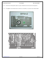
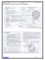
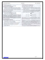
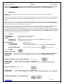
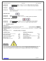
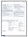
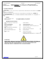
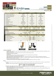
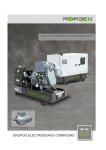
Manual GPM-2 Manuel
31/03/2009
Impr: 02/04/2009
Español ............................................................................................. Pag: 2 - 7
English ............................................................................................. Pag: 8 - 12
Français ........................................................................................... Pag: 13 - 19
www.abamotor.com
REF: 520
Pag:
1
Manual GPM-2 Manuel
31/03/2009
Impr: 02/04/2009
PUESTA EN SERVICIO Y MANTENIMIENTO DEL GRUPO
ELECTROGENO (G.E.) CON CUADRO GPM-2
Recuerde que el automatismo depende exclusivamente de la batería, por lo que hay que
tener muy en cuenta el consumo de los elementos que se conecten a la tarjeta Genalt
GPM-2.
1.º IMPORTANTE: Si por alguna razón la batería que se va a instalar no es nueva,
recuerde que puede estar en mal estado aunque trabajando en vacío la tensión sea la
correcta (12’70V).
2.º Llene completamente el depósito de gasoil.
3.º Si por la razón que fuese no pudiese llenar completamente el depósito, recuerde que
tiene que haber gasoil suficiente para sobrepasar el nivel de salida del combustible.
4.º Llene el motor con la cantidad correcta de aceite (Ver manual motor), y compruébelo
con la varilla (no sobrepasar nunca el nivel máximo indicado en ella).
5.º Conecte la tierra al cuadro en el tornillo situado en la base inferior del mismo.
6.º Si el GE va instalado en una zona urbana resulta muy conveniente la colocación de un
silencioso residual de escape. Solicite información si lo considera necesario.
7.º Compruebe que los fusibles del cuadro automático estén en buen estado. Si están
fundidos la tarjeta detectará el fallo parando el motor.
8.º En caso de interrupción del suministro eléctrico del G.E. sin que la tarjeta nos indique
fallo alguno, compruebe si ha saltado el magnetotérmico montado en el cuadro.
9.º El grupo electrógeno no debe trabajar a la intemperie. Abamotor declinará cualquier
responsabilidad ante anomalías de funcionamiento que puedan derivarse de este hecho.
10.º DEBE REALIZAR UNA PRUEBA QUINCENAL para comprobar el correcto funcionamiento
del grupo electrógeno.
11.º
LEASE LA HOJA DE INTRUCCIONES DEL CUADRO AUTOMATICO.(A continuación)
www.abamotor.com
REF: 520
Pag:
2
Manual GPM-2 Manuel
31/03/2009
Impr: 02/04/2009
12.º
En caso de emergencia pare el grupo mediante la seta roja de emergencia.
13.º
El negativo de la batería es lo último en conectar y lo primero en desconectar.
12VDC
24VDC
24VDC
EINSCHALT.
12VDC
www.abamotor.com
REF: 520
Pag:
3
Manual GPM-2 Manuel
31/03/2009
Impr: 02/04/2009
GPM-2, es un protector de motor programable, ideado para el control y vigilancia de grupos
electrógenos, motores, compresores, motobombas, etc., pudiendo ser utilizado indistintamente
con baterías de 12 y 24Vcc. con posibilidad de alarmas a distancia.
1. FUNCIONAMIENTO
GPM-2 dispone de dos modos de funcionamiento según la posición de la llave: MANUAL y AUTOMATICO.
Accionando el pulsador de arranque, se producirá la correspondiente orden al motor. El arranque se retirará
cuando se apaguen las señales de “BAJA PRESION DE ACEITE”, “ALTER. CARGA DE BATERIAS” ó con frecuencia
superior a
20Hz.
Con la llave en posición “MAN”, se iluminan las indicaciones de “BAJA PRESIÓN DE ACEITE” y “ALTERNADOR
DE CARGA DE BATERÍAS”, caso de no accionar el pulsador de arranque, transcurridos 60seg. , GPM-2 manda
parar, y se activa la señal de bocina durante 120 seg.
Con la llave en posición “AUTO”, y sí las bornas 1 y 2 están cerradas, se iluminan las indicaciones de “BAJA
PRESIÓN DE ACEITE” y “ALTERNADOR DE CARGA DE BATERÍAS” se ordena la marcha automática del grupo,
encendiéndose el led correspondiente (AUTO TEST). Se pueden producir hasta 3 intentos de arranque. Si el
grupo no arranca al tercer intento se ilumina la alarma de “FALLO DE ARRANQUE”. Cuando se abren las bornas
1 y 2, temporiza marcha en vacío, y se ordena la parada del motor. GPM-2 queda desactivado (sin consumo
de batería), quedando disponible para un nuevo servicio.
La línea de potencia y la línea de arranque a distancia deberán ir separadas, así mismo, se recomienda la
colocación de un relé intermedio, repetidor de arranque automático, para distancias iguales o superiores a 20
metros.
2. INDICACIONES
- AUTO TEST:
Verde fijo /Marcha en remoto
- PREIGNICION:
Amarillo fijo / Preignición
- STOP:
Rojo
Led intermitente: Indicación de marcha en vacío durante 60sg. transcurridos los cuales GPM-2
manda
parar.
Led fijo:
Orden de parada, 20sg.
MANTENIMIENTO:
1er mantenimiento:
2º mantenimiento:
RESET MANTENIMIENTO:
Amarillo intermitente
Transcurridas 50 horas de funcionamiento
Transcurridas 150 horas del primer mantenimiento (programable)
Pasar la llave a posición “STOP” y durante el tiempo de parada pulsar
3. ALARMAS
FALLO DE ARRANQUE
Led intermitente: Después de tres intentos fallidos, se activa la señal de bocina. GPM-2 manda parar.
Led fijo:
“Alarma por fallo de tensión ó baja frecuencia”, se activa la señal de bocina. GPM-2
manda parar.
FALLO CARGA BATERIAS (ROTURA DE CORREAS) (Temporizada 20sg.)
Led fijo:
Motor parado (antes del arranque), solo Indicación.
Led intermitente: “Alarma Fallo de carga baterías”, se activa la señal de bocina. GPM-2 manda parar.
www.abamotor.com
REF: 520
Pag:
4
Manual GPM-2 Manuel
31/03/2009
Impr: 02/04/2009
BAJA PRESIÓN DE ACEITE (Temporizada 2º seg)
Led fijo:
Motor parado (antes del arranque), sólo indicación
“Alarma Baja presión de aceite”, se activa la señal de bocina. GPM-2 manda parar.
Led intermitente:
SOBRETEMPERATURA / BAJO NIVEL DE AGUA
“Alarma Bajo nivel de agua” se activa la señal de bocina. GPM-2 manda parar.
Led fijo:
Led intermitente: “Alarma Alta temperatura de agua” se activa la señal de bocina. GPM-2 manda parar.
SOBRECARGA
Led intermitente: “Alarma Sobrecarga” se activa la señal de bocina, y transcurrido el tiempo programado de marcha
en
vacío, GPM-2 manda parar.
BAJO NIVEL DE COMBUSTIBLE
Led fijo:
“Alarma Bajo nivel de combustible” se activa la señal de bocina.
Led intermitente: “Alarma Bajo nivel de combustible” se activa la señal de bocina. GPM-2 manda parar.
PARADA DE EMERGENCIA / SOBREVELOCIADAD
Led intermitente: “Alarma Parada de emergencia” se activa la señal de bocina. GPM-2 manda parar.
Led fijo:
4.
“Alarma Sobrevelocidad” se activa la señal de bocina. GPM-2 manda parar.
DATOS TÉCNICOS
ALIMENTACIÓN
12 y 24Vcc nominal: (máxima 17,5 Vcc y 35 Vcc, respectivamente)
seleccionable mediante “JUMPER J4”.
CEBADO DEL ALTERNADOR: Cebado a 12Vcc. Cebado a 24Vcc. Sin cebado.
seleccionable mediante “JUMPER J2”.
RETIRADA DE ARRANQUE: Por “PRESOSTATO DE ACEITE”, y “SEÑAL ALTERN CARGA BATERÍAS”, ó “frecuencia” >20Hz.
-SALIDAS
Contacto, Arranque y Parada:
Alarma (Bocina):
+Vcc (positivo de batería), 10 A máximo.
-Vcc (negativo de batería), 1 A máximo.
TEMPORIZACIONES STANDARD
Permanencia de alarmas para ser consideradas:
Retardo alarmas diferidas:
Duración de preignición:
Orden de arranque/pausa automático:
Permanencia de la orden de parada:
Duración de la salida de bocina:
Marcha en vacío
Retardo alarma tensión generador.
CONFIGURACIÓN STANDARD
1seg.
20seg.
10seg.
10seg.
20seg.
2min.
1min.
30seg.
Tensión batería:
24Vcc.
Cebado alternador:
SI
Intentos arranque/pausa:
3
Retirada arranque: P. Aceite, alt, Crg.Bat ó Fr>20Hz
Frecuencia generador:
50Hz
Retardo alarma baja frecuencia:
30seg.
Permanencia sobrevelocidad.
½ seg.
Retardo conexión generador:
10 seg.
¡CUIDADO!
DADO QUE LOS GENERADORES DE BATERÍA, EN CASO DE DESCONEXIÓN DE LA BATERÍA CON GRUPO EN MARCHA
GENERAN UNA TENSIÓN DE ENTRE 50 Y 200 VOLTIOS (DESTRUCTIVA PARA LA ELECTRÓNICA), SE DEBEN EVITAR
ABSOLUTAMENTE OPERACIONES EN LAS CONEXIONES CON EL GRUPO EN MARCHA.
www.abamotor.com
REF: 520
Pag:
5
Manual GPM-2 Manuel
31/03/2009
Impr: 02/04/2009
INTERRUPTOR HORARIO DIGITAL PROGRAMABLE
www.abamotor.com
Pag: 6
Manual GPM-2 Manuel
www.abamotor.com
31/03/2009
Impr: 02/04/2009
Pag: 7
Manual GPM-2 Manuel
31/03/2009
Impr: 02/04/2009
STARTING AND MAINTENANCE OF GENERATING SET WITH
AUTOMATIC CONTROL BOARD GPM-2
Remember that the automatic device is depending of the battery. So you have to consider
the consumption of the elements that is connected to the automatic card.
1.º IMPORTANT: If the battery to install isn´t new can be out-of-order although the voltage in
mode no-load operation would be correct (12’70V).
2.º The fuel tank must be filled because the generating set can be working a long time.
3.º Remember that the fuel has to be sufficient to pass the output level.
4.º The oil sump must be with oil sufficient (read the engine manual). Check the oil level with Oil
dipstick. Never override the maximun oil level.
5.º Earth use the screw located on lower base of AUTOMATIC CONTROL BOARD.
6.º If the generator is installed in a city, town, neighbourhood… it could be necessary to install a
special exhaust pipe. Ask information about it.
7.º Check fuses. If these are broken the automatic card will not start the group.
8.º In case of power-supply interrupt and the automatic card don´t display any light signal, check
magnetothermic
9.º The generating set don´t must to work exposure to weather. Abamotor Energía don´t support
any responsibility relate with malfunction of generating set for this assignable cause.
10.º Every 15 days check generating set operation.
11.º
Read carefully the instruction manual of the automatic card.
12.º In case of emergence stop the generating set use the emergency button .
13.º
The negative of the battery is the last to connect and the first to disconnect.
www.abamotor.com
Pag: 8
Manual GPM-2 Manuel
31/03/2009
Impr: 02/04/2009
GPM-2 is a programmable engine protector, designed to control and monitor generators, engines,
compressors and motorised pumps, etc. It can be used with either 12 or 24V DC batteries.
1. OPERATION
GPM-2 has two operating modes, which can be selected by turning the switch to either MANUAL or
AUTOMATIC.
Pressing the start button will send the corresponding command to the engine. Ignition will be deactivated when
the “LOW OIL PRESSURE” or “BATTERY CHARGE ALTERNATOR” pilot lights go off or the frequency exceeds
20Hz.
When the switch is turned to “MAN”, the “LOW OIL PRESSURE” and “BATTERY CHARGE ALTERNATOR” pilot
lights will come on. If the start button has not been pressed after and intervale of 60seconds, the GPM-2 will
stop the process and activate a siren for 120 seconds.
When the switch is turned to “AUTO” and terminals 1 and 2 are both closed, the “LOW OIL PRESSURE” and
“BATTERY CHARGE ALTERNATOR” pilot lights will come on. Automatic operation is enabled and the
corresponding LED pilot light (AUTO TEST) is lit. The device will permit 3 ignition attemps. If the group does not
start after the third attemp, the “START FAILURE” alarm will be triggered. When terminals 1 and 2 are opened,
the system times an off-load running period and then commands the engine to stop. GPM-2 then disconnects
from the battery and is available for a new service.
2. SIGNALS
- AUTO TEST:
- PRE-IGNITION:
- STOP:
Flashing LED:
Constant LED:
Constant green / Remote operation
Constant yellow / Pre-ignition
Red
Off-load running for 60 seconds, after which GPM-2 stops the engine.
Stop command, 20 seconds
MAINTENANCE:
1st maintenance:
2nd maintenance:
RESET MAINTENANCE:
Flashing yellow
After 50 operation hours
150 operating hours after the first maintenance (programmable)
Turn the switch to “STOP” and press
during stop time.
3. ALARMS
START UP FAILURE
Flashing LED:
Constant LED:
command
After three failed attemps, the siren is activated and the GPM-2 send a stop command.
“Low voltage or frequency alarm”, the siren is activated. The GPM-2 sends a stop
BATTERY CHARGE FAILURE (BELTS BROKEN) (Timed: 20sec.)
Constant LED:
Flashing LED:
command
Engine stopped (before start up), signal only.
“Battery charge failure alarm”, the siren is activated. The GPM-2 sends a stop
LOW OIL PRESSURE (Timed: 20 sec)
Constant LED:
Flashing LED:
Engine stopped (before start up), signal only.
“Low oil pressure alarm”, the siren is activated. The GPM-2 sends a stop command
EXCESS TEMPERATURE / LOW WATER LEVEL
www.abamotor.com
Pag: 9
Manual GPM-2 Manuel
31/03/2009
Impr: 02/04/2009
Constant LED:
“Low water level alarm” the siren is activated and GPM-2 sends a stop command.
Flashing LED:
“High water temp alarm” the siren is activated and GPM-2 sends a stop command.
OVERLOAD
Flashing LED:
“Overload alarm”: the siren is activated and, after the programmed off-load running time, the GPM-2
sends a stop command.
LOW FUEL LEVEL
Constant LED:
“Alarm Low fuel level” the siren is activated..
Flashing LED:
“Alarm Low fuel level” the siren is activated and the GPM-2 sends a stop command.
EMERGENCY STOP / EXCESS SPEED
Flashing LED:
“Alarm emergency stop” the siren is activated and the GPM-2 sends a stop command.
Constant LED:
“Alarm excess speed” the siren is activated and the GPM-2 sends a stop command.
4.
TECHNICAL DATA
POWER SUPPLY
12 and 24Vcc nominal: (max 17,5 Vcc and 35 Vcc, respectively)
Can be selected using “JUMPER J4”.
ALTERNATOR PRIMING: Priming at 12V DC.No priming
Can be selected using “JUMPER J2”.
IGNITION DISABLE: Due to “OIL PRESSURE METER , and “BATTERY CHARGE ALTERN SIGNAL”, or “FREQUENCY” >20Hz.
-OUTPUTS
Contact, Start up and Stop:
Alarma (Bocina):
+V DC (battery positive), 10 A maximum
-V DC (bettery negative), 1 A maximum.
STANDARD TIMING
Duration of alarms in order to be noted:
Delay of differed alarms:
Duration of pre-ignition:
Automatic start up/Pause command:
Duration of stop command:
Duration of siren output:
Off-load running:
Generator voltage alarm delay:
STANDARD CONFIGURATION
1sec.
20sec.
10sec.
10sec.
20sec.
2min.
1min.
30sec.
Battery voltage
Alternator priming:
Start up / pause attemps:
Start up disable: L. Oil, Alt, Crg.Battery or
Generator frequency:
Low frequency alarm delay:
Duration excess speed.
Generator connection delay:
24V DC.
YES
3
Fr>20Hz
50Hz
30sec.
½ sec.
10 sec.
BEWARE !
SINCE THE BATTERY CHARGER GENERATORS, IF DISCONNECTED FROM THE BATTERY WHEN THE
UNIT IS RUNNING, GENERATE BETWEEN 50 AND 200 VOLTS (DESTROYS ELECTRONICS), IT IS
ABSOLUTELY ESSENTIAL NOT TO WORK ON THE CONNECTIONS WHEN THE UNIT IS RUNNING.
www.abamotor.com
Pag: 10
Manual GPM-2 Manuel
31/03/2009
Impr: 02/04/2009
CLOCK USERS GUIDE
www.abamotor.com
Pag: 11
Manual GPM-2 Manuel
www.abamotor.com
31/03/2009
Impr: 02/04/2009
Pag: 12
Manual GPM-2 Manuel
31/03/2009
Impr: 02/04/2009
POUR COMMENCER A TRAVAILLER ET LE MAINTENANCE DU
GROUPE AVEC COFFRET GPM-2
Il faut rappeler, que le coffret automatismos travaille grâce à Batterie, il faut prende
attention au consomations des êlément a conecter sur l’automatisme GPM-2
1.º IMPORTANT: Si la batterie n’est pas nouveau vous devez rappeler que c’est possible que
la batterie est mal bien que la tension est correct. (12’70V).
2.º Remplir complètement le réservoir de gasoil
3.º Si ce n’est pas possible remplir complètement le réservoir rappelez-vous que le gasoil
doit surpasser le niveau de sorti du combustible.
4.º Remplir le moteur avec la quantité d’huile correcte (lire le manual du moteur), et
vérifier avec la baleine (ne pas surpasser le limite supérieur de la baleine)
5.º Connecte la terre au tableau sur le vis qui est dans la base inférieur du tableau.
6.º Si le groupe est installe dans une zone urbaine c’est mieux faire la colocation d’un pot
d’échappement résiduel. Demande information si vous avez quelque doute.
7.º Vérifiez-vous que les fusibles sont bien. Si quelque fusible est casse le tableau
électronique trouvera un erreur et le groupe s’arrêtera.
8.º Si le approvisionnement électrique du groupe se coupe sans que le tableau électronique
montre erreur, voir si le magnétothermique a sauté dans le tableau.
9.º Le groupe électrogène ne doit pas travailler au intempérie. Abamotor n’acceptera pas
responsabilité par anomalies de fonctionnement que puissent venir de ce fait.
10.º DEVEZ- VOUS FAIRE UN TEST CHAKE 15 JOURS pour voir le correct fonctionnement
du groupe électrogène
11.º
Lire le manuel de instruction du tableau électronique.
12.º
Pour une émergence arrêtez-vous le groupe avec le bouton rouge d’émergence.
www.abamotor.com
Pag: 13
Manual GPM-2 Manuel
31/03/2009
Impr: 02/04/2009
Le négatif du Batterie est le dernière chose peur et connecter la première en dé connector
12VDC
24VDC
24VDC
EINSCHALT.
12VDC
GPM-2 est un protecteur de moteur programmable, conçu pour le contrôle et la surveillance de
groupe électrògenes, moteurs, compresseurs, motopompes, etc, qui peut être utilisé
indistinctement avec des batteries 12 et 24Vcc.
1. FONCTIONNEMENT
GPM-2 dispose de deux modes de fonctionement selon la position de la clé: MANUEL et AUTOMATIQUE
En actionant le bouton de demarraje, l’ordre correspondant sera donné au moteur. Le demarrage se retire
quand les signaux de “BASSE PRESIÓN HUILE”, “ALTER. CHARGE BATTERIE” s’éteignent ou avec une fréquence
supérieure à 20Hz.
www.abamotor.com
Pag: 14
Manual GPM-2 Manuel
31/03/2009
Impr: 02/04/2009
Avec la clé sur la position “MAN”, les indications “ BASSE PRESSION HUILE” et “ALTERNATEUR DE CHARGE
BATTERIES”, s’allument et si le bouton de démarrage n’est pas enfoncé dans le 60 secondes qui suivent, GPM2 envoie l’ordre d’arrêter et le signal sonore s’active durant 120 secondes.
Avec la clé sur la position “AUTO”, et si les bornes 1 et 2 sont fermées, les indications “BASSE PRESIÓN HUILE”
et “ALTERNATEUR DE CHARGE DES BATTERIES” s’allument, et l’ordre de marche automatique du groupe est
donné, le led correspondant (AUTO RESET) s’allume également. Possibilité de faire 3 tentatives de démarrage.
Si le groupe ne démarre pas à la troisième tentative, l’alarme “DÉFAILLANCE DE DEMARRAGE” s’allume et
l’ordre d’arrêter le moteur est donné, GPM-2 se déconnecte de la batterie et reste disponible pour un nouveau
service.
2. INDICATIONS
- AUTO-TEST :
Vert fixe/Marche à distance
- PRÉIGNITION
Jaune fixe/Pré.ignition
- STOP :
Rouge
Led intermittent : Indication de marche à vide durant 60secondes après lesquelles, GPM-2 donne l’ordre
d’arrêter.
Led fixe : Ordre d’arrêt, 20 secondes.
- MAINTENANCE :
Jaune internittent
1ère maintenance :
Après 50 heures de fonctionnement
2e maintenance :
Après les 150 heures qui suivent la lère maintenance (programmable)
RESET MAINTENANCE : Passer la clé sur la position « STOP » et durant le temps d’arret, appuyer
3. ALARMES
- DÉFAILLANCE DE DÉMARRAGE
Led intermittent :
l’arrêt.
Led fixe :
Après trois tentetives négatives, le signal sonore se déclenche. GPM-2 ordonne
« Alarme par défaillance de tension ou basse fréquence »,le signal sonore s’active.
GPM-2 ordonne d’arrêter.
- DEFAILLANCE CHARGE BATTERIES (RUPTURE DES COURROIES)
(temporisée 20 secondes)
Led fixe :
Led intermittent :
Moteur arrêté avant le démarrage, indication seulement.
« Alarme Défaillance charge batteries », le signal sonore s’active. GPM-2 ordonne
l’arrêt.
- BASSE PRESSION HUILE
(temporisée 20 secondes)
Led fixe :
Led ermitent :
Moteur arrête (avant le démarrage). Indication seulement.
« Alarme Basse pression huile » le signal sonore s’active. GPM-2 ordonne l’arrêt.
- SURCHAUFFE/BAS NIVEAU EAU
Led fixe :
Led intermittent :
l’arrêt
- SURCHARGE
Led intermittent :
« Alarme Bas niveau eau » le signal sonore s’active. GPM-2 ordonne l’arrêt.
« Alarme Température eau élevée » le signal sonore s’active. GPM-2 ordonne
« Alarme surcharge » le signal sonore s’active et quand le temps de marche
programmé s’est écoulé à vide, GPM-2 ordonne l’arrêt.
- BAS NIVEAU COMBUSTIBLE
Led fixe :
Led intermittent :
« Alarme Bas niveau combustible », le signal sonore s’active.
« Alarme Bas niveau combustible », le signal sonore s’active. GPM-2 ordonne l’arrêt.
- ARRÊT D’URGENCE/SURVITESSE
www.abamotor.com
Pag: 15
Manual GPM-2 Manuel
Led fixe :
Led intermittent :
31/03/2009
Impr: 02/04/2009
« Alarme Survitesse » le signal sonore s’active. GPM-2 ordonne l’arrêt.
« Alarme Arrêt d’urgence » le signal sonore s’active. GPM-2 ordonne l’arret.
4. DONNÉES TECHNIQUES
ALIMENTATION :
12/24Vcc nominale : max 17,5Vcc et 35 Vcc, respectivement) selectionable par l’intermédiaire de « JUMPER
J4 »
AMORCE DE L’ALTERNATEUR :
Amorce à 12 Vcc. Amorce à 24Vcc. Sans amorce. Selectionable par l’intermédiaire de « JUMPER J2 »
RETRAIT DE DÉMARRAGE :
Par « PRESSOSTAT AT D’HUILE », et « SIGNAL ALTERNATEUR CHARGE BATTERIES » ou « FREQUENCE » >
20Hz
-
SORTIES
Contact, Démarrage, Arrêt :
Alarme (Sonore) :
-
+ Vcc (Positif de batterie), 10A maximum.
- Vcc (Negatif de batterie), 1A minimum.
TEMPORISATIONS STANDARD
Durée des alarmes pour quélles soient
24Vcc
Prises en considération
Retard alarmes différées :
Durée de pré-ignition
Tension batterie :
1s.
20s.
10s.
Amorce alternateur :
Tentatives Démarrage/pause :
Retrait dámarrage : P.huile, Charge batt, Ele, ou
10s.
Fréquence Générateur :
20s.
2mn
Retard alarme basse fréquence :
Durée survitesse :
1mn
Retard connexion géné :
OUI
3
Fr>20Hz
Ordre démarrage/Pause automatique
50Hz
Durée de l’ordre d’arrêt :
Durée de sortie du signal sonore :
s.
Marche à vide :
10s.
30s.
½
Emergence contact stop :
NC
(selectionable par l’intermédiaire de « JUMPER J5 »)
ATTENTION !!!
ÉTANT DONNÉ QUÉN CAS DE CONNEXION DE LA BATTERIE AVEC LE GROUPE EN MARCHE, LES
GÉNÉRATEURS CHARGEURS DE BATTERIE, GÉNÈRANT UNE TENSION D’ENTRE 50 ET 200VOLTS,
(DESTRUCTIVE POUR L’ÉLECTRONIQUE) IL FAUT ABSOLUMENT ÉVITER TOUTES
OPÉRATIONS DANS LES CONNEXIONS AVEC LE GROUPE EN MARCHE.
www.abamotor.com
Pag: 16
Manual GPM-2 Manuel
31/03/2009
Impr: 02/04/2009
MODE D’EMPLOI:
www.abamotor.com
Pag: 17
Manual GPM-2 Manuel
www.abamotor.com
31/03/2009
Impr: 02/04/2009
Pag: 18
Manual GPM-2 Manuel
www.abamotor.com
31/03/2009
Impr: 02/04/2009
Pag: 19
Manual GPM-2 Manuel
31/03/2009
Impr: 02/04/2009
ABAMOTOR ENERGÍA, S.L.
Astola, 6-C
-
48220 Abadiano (Vizcaya)
España / Spain / Espagne
Telfs: 34 - 94 620 27 17 ---- 34 94 620 27 41
Fax: 34 - 94 620 33 34
E-mail: [email protected]
www.abamotor.com
***** http://www.abamotor.com
Pag: 20