1
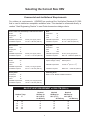
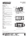
OPERATION AND
INSTALLATION MANUAL
For Models:
IMPORTANT - PLEASE READ THIS
MANUAL BEFORE INSTALLING UNIT
2500IFD
2500EFD
CAUTION
Before installation, careful consideration must be given to
how this system will operate if connected to any other piece
of mechanical equipment, i.e. a forced air furnace or air
handler, operating at a higher static. After installation, the
compatibility of the two pieces of equipment must be
confirmed by measuring the airflow’s of the Heat Recovery
Ventilator (HRV) Energy Recovery Ventilator (ERV) by
using the balancing procedure found in this manual.
It is always important to assess how the operation of any
HRV/ERV may interact with vented combustion equipment
(ie. Gas Furnaces, Oil Furnaces, Wood Stoves, etc.).
NEVER install a ventilator in a situation where its normal
operation, lack of operation or partial failure may result
in the backdrafting or improper functioning of vented
combustion equipment!!!
TO BE COMPLETED BY CONTRACTOR AFTER INSTALLATION
Installing Contractor
Telephone / Contact
Serial Number
Installation Date
Model
* LEAVE FOR HOMEOWNER
NOTE: Due to ongoing research and product development, specifications,
ratings and dimensions are subject to change without notice.
TI-59
1203
Introduction
Table of Contents
These Heat Recovery Ventilators (HRVs) are designed
for commercial and industrial applications to provide
fresh air to a building while exhausting an equal
amount of stale air. During the winter months the
incoming cold fresh air is warmed by utilizing the heat
recovered from the stale air before it is exhausted to
the outdoors. During summer months when the indoor
space is air conditioned, the Heat Recovery Ventilator
will help in cooling the incoming fresh air with the stale
air that is being exhausted.
Introduction .................................................................... 2
Select Correct HRV......................................................... 3
Specifications - Model 2500IFD .................................. 4
Specifications - Model 2500EFD ................................. 5
Options & Accessories ....................... 6
Operation Instructions ................................................... 7
Installation Tips ............................................................. 7
Remote Controls ........................................................... 8
2500
I
F
D
User Adjustable Defrost ................................................ 8
Defrost Control .............................................................. 8
Interior
mount
Fan
Fan Defrost ................................................................. 9
Defrost
Location ...................................................................... 9
Mounting ..................................................................... 9
Drains ......................................................................... 12
2500
E
F
Ducting ......................................................................... 12
D
Return and Supply ....................................................... 13
Exterior
(roof mount)
Fan
Air Flow Balancing ....................................................... 14
Defrost
The Integrated HVAC System ...................................... 15
Electrical Connections ................................................. 15
Maintenance ................................................................ 15
Wiring Diagram ........................................................... 17
Ladder Diagram .......................................................... 18
Warranty .................................................................... 19
2
Selecting the Correct Size HRV
Commercial and Institutional Requirements
For outdoor air requirements, ASHRAE has produced the Ventilation Standard 62-1989
that is used to determine acceptable ventilation rates. This standard is referenced directly or
used as “Good Engineering Practice” in most Code documents or design criteria.
Small restaurants, Donut Shops and Fast food stores
Seats
40
Employees
5
Total
45
ASHRAE requirement
20 cfm (10 L/s) per person
Ventilation required
45 x 20 = 900 cfm (450 L/s)
Bank
Customers
25
Staff
9
Total
34
ASHRAE requirement
Ventilation required
20 cfm (10 L/s) per person
34 x 20 = 680 cfm (320 L/s)
Bar or Tavern
Seats
50
Employees
7
Total
57
ASHRAE requirement
Ventilation required
Bingo Hall
Customers
180
Staff
20
Total
200
ASHRAE requirement
Ventilation required
30 cfm (15 L/s) per person
200 x 30 = 6000 cfm (3000 L/s)
30 cfm (15 L/s) per person
57 x 30 = 1710 cfm (855 L/s)
Classroom and School Portables
Seats
29
Teacher
1
Total
30
ASHRAE requirement
15 cfm (7.5 L/s) per person
Ventilation required
30 x 15 = 450 cfm (255 L/s)
Print Shop, Duplicating
Square footage of shop
2000 square ft
Beauty Salon
Customers
12
Employees
6
Total
18
ASHRAE requirement
Ventilation required
Swimming Pools
Refer to “Pool” Models Installation Manuals.
ASHRAE requirement
0.5 cfm / ft2 (2.5 L/s - m2)
Ventilation required
2000 x 0.5 = 1000 cfm (500 L/s)
25 cfm (12.5 L/s) per person
18 x 25 = 450 cfm (255 L/s)
MAKE UP HEAT REQUIREMENT at 1200 CFM (566L/s)
Outdoor Temp.
C°
F°
0
-10
-20
-30
-40
32
14
-4
-22
-40
Nominal
kW Req. for
20°C (68°F)
Air Delivery
7
10
12
15
17
Nominal
Nominal
kW Req. for
kW Req. for
25°C (77°F)
30°C (86°F)
Air Delivery
Air Delivery
10
14
15
19
21
3
14
17
19
22
24
Model 2500IFD
SPECIFICATIONS
AIR FLOW
2100 cfm (985 L/s) at 1.0"wg ESP
Supply from Outside
PERFORMANCE
Exhaust to Outside
70% effective at 2500 cfm (1172 L/s)
CORE
4" Filters
Modular aluminum sensible heat recovery core.
Plate-to-plate type. Slides out of either side of cabinet for
service.
MOTORS
Motors (2)
Two single shaft PSC, 3-speed, 208/230V,5.1 amps,
Exhaust from Building
1 ph, 1 hp
BLOWERS
Two direct-drive centrifugal blowers, one per air stream.
Heat Exchange Core
FILTERS
Supply to Building
Two 18" X 24" 4-inch pleated filters in each air stream.
Drain Pans (2)
DUCT CONNECTIONS
Four 24" X 16" (610mm X 406mm)
CABINET
Heat
Filter
Electrical
20 gauge powder coated galvanized steel (G60) for
Exchanger
Service
Service
superior corrosion resistance. 16 gauge galvanized
Service
Panel*
Panel*
47"
Panel*
frame, insulated with1.5" fibreglass insulation to prevent
condensation.
DRAIN
Two stainless steel drain pans with 1/2" NPT drain
89.9"
spouts.
SIDE VIEW
MOUNTING
Unit to be set on support brackets hung by threaded rod
*NOTE: Removable service access panels on both sides of 2500IFD cabinet.
type apparatus. Brackets and rod not provided.
CONTROLS
Supply from
24V terminal strip inside electrical box, to connect
outside
2"
optional remote controls (not included), obtain on/off and
38.4"
38.4"
high/low functions.
Exhaust to
24"
24"
DEFROST
outside
Factory set defrost time (user adjustable).
7"
Supply motor is shut off while exhaust air defrosts core.
47"
WARRANTY
Supply to
16"
16"
15 year warranty on heat exchanger, and 2 years
building
on parts.
6"
WEIGHT
Exhaust from
building
700 lbs.
SHIPPING WEIGHT
FRONT VIEW
BACK VIEW
1100 lbs.
All units conform to CSA and UL standards.
DATE: ______________________________________________PROJECT: ______________________________________
MECHANICAL CONTRACTOR: _________________________________________________________________________
4
TI-91I
1203
Model 2500EFD
(ROOFTOP)
SPECIFICATIONS
AIR FLOW
2100 cfm (985 L/s) at 1.0"wg ESP
PERFORMANCE
70% effective at 2500 cfm (1172 L/s)
CORE
Modular aluminum sensible heat recovery core.
Plate-to-plate type. Slides out of either side of cabinet
for service.
MOTORS
Two single shaft PSC, 3-speed, 208/230V,5.1 amps, 1 ph,
1 hp
BLOWERS
Two direct-drive centrifugal blowers, one per air stream.
FILTERS
Two 18" X 24" 4-inch pleated filters in each air stream.
DUCT CONNECTIONS
Four 24" X 16" (610mm X 406mm) to and from the building
under cabinet. Four 28" X 18" (711mm X 457mm) hoods
included on side of cabinet with screens.
CABINET
20 gauge powder coated galvanized steel (G60) for
superior corrosion resistance. 16 gauge galvanized
frame, insulated with 1.5" fibreglass insulation to prevent condensation.
DRAIN
Two stainless steel drain pans with 1/2" NPT drain
spouts.
MOUNTING
Rooftop mounted on optional roof curb (Part No. 532500)
CONTROLS
24V terminal strip inside electrical box, to connect
optional remote controls (not included), obtain on/off
and high/low functions.
DEFROST
Factory set defrost time (user adjustable).
Supply motor is shut off while exhaust air defrosts core.
WARRANTY
15 year warranty on heat exchanger, and 2 years on
parts.
WEIGHT
700 lbs.
SHIPPING WEIGHT
1100 lbs.
OPTIONAL CURB
WEIGHT 50 lbs.
Hoods (2)
c/w Bug Screen
Exhaust
Hoods
Supply Hoods
4" Filters
Motors (2)
Roof Curb
Exhaust Duct
24"x16"
Heat Exchange Core
Supply Duct
24"x16"
Drain Pans (2)
*NOTE: Roof curb is one inch smaller than outside dimensions of cabinet.
Heat
Exchanger
Service
Panel*
Electrical
Service
Panel*
Filter
Service
Panel*
18"
47"
18"
27"
89.9"
SIDE VIEW
*NOTE: Removable service access panels on both sides of 2500EFD cabinet.
44.95"
8"
Hood
8"
44.95"
25"
21.8"
Bottom duct
connections
16" X 24"
12"
8"
8"
Hood
12"
38.4"
28"
12"
Fresh Air
Supply
19.2"
Centre
Point
12"
89.9"
Stale Air
Return
BOTTOM VIEW
All units conform to CSA and UL standards.
DATE: ____________________________________________PROJECT: ________________________________________
MECHANICAL CONTRACTOR: __________________________________________________________________________
5
TI-91E
1203
Performance
AIRFLOWS (Each Air Stream)
HIGH SPEED
AIRFLOW L/s (CFM)
1316 (2800)
1175 (2500)
1034 (2200)
MEDIUM SPEED
893 (1900)
LOW SPEED
752 (1600)
611 (1300)
470 (1000)
329 (700)
188 (400)
47 (100)
25 50 75 100 125 150 175 200 225 250 275 300 325 350 375 400 425 450 475 500 525 550
(0.1) (0.2) (0.3) (0.4) (0.5) (0.6) (0.7) (0.8) (0.9) (1.0) (1.1) (1.2) (1.3) (1.4) (1.5) (1.6) (1.7) (1.8) (1.9) (2.0) (2.1) (2.2)
EXTERNAL STATIC PRESSURE IN PASCALS (in. W.C.)
EFFECTIVENESS
TEMPERATURE EFFECTIVENESS
70%
60%
50%
NOTE: Exhaust Relative Humidity (RH) at 40%
850
944
1039
1133
1228 1322
1416
(1800) (2000) (2200) (2400) (2600) (2800) (3000)
AIRFLOW IN L/s (CFM)
Roof Curb (optional)
Part No. 53-2500
Options and Accessories
Supply air
opening
Duct Collar Supports
99-101: CRANK TIMER
Mechanical timer to activate high speed.
99-116: DEHUMIDISTAT VENTILATION CONTROL (DVC)
Turns unit on/off via slider switch and high/low via built-in
dehumidistat.
Factory installed
perimeter wooden
nailer strip
Return air
opening
99-130: DEHUMIDISTAT
Activates high speed when indoor humidity
rises above set point on control.
8"
99-140: 4" TECHGRILLE
99-141: 5" TECHGRILLE
99-142: 6" TECHGRILLE
99-148: 8" TECHGRILLE
Round, white, step-type diffusers.
8"
12"
25"
21.8"
Bottom duct
connections
16" X 24"
8"
8"
12"
36.5"
Centre
Point
12"
53-2500: OPTIONAL ROOF CURB
Supports HRV on roof and connects
HRV to ducting below.
WEIGHT: 50lbs
12"
Stale Air
Return
Fresh Air
Supply
88.5"
TOP VIEW
Information about design-built electric make-up heat
coils available upon request.
0.7"
14"
SIDE VIEW
6
Operation Instructions
Installation Tips
The LIFEBREATH 2500 series HRV is designed
tobe operated continuously or intermittently to meet
the requirements of the application.
1. Whichever method is chosen to operate the
2500, keep in mind that Air-to Air exchangers
in general are not "booster fans" and are
normally sized to ventilate at a steady rate.
Continuous Operation
To achieve optimum performance from the
2500, the desired ventilation rate (speed of
the system) should be reached before the
contaminant to be removed has reached
its maximum.
For continuous operation, a simple jumper across
the ON/OFF and COMMON jumper terminals is
needed. HIGH/LOW speed selection requires
another jumper across HIGH/LOW and COMMON;
select as required (see below and wiring diagram).
EXAMPLE: A bingo hall opening at 7:00PM that is
sized for 5000 cfm should have at least this amount
of air exchange by that time. If the unit is not turned
on or set to its designated speed until after the contaminant has reached an uncomfortable level, then
it may result in a number of hours
passing before the system could catch up.
T3 - On/Off
ON/OFF
T2 - High/Low
2. It is highly recommended that back draft
dampers be installed in the supply and
exhaust duct work to the outside, to prevent
air from entering in through the HRV when the
unit is off. Failure to install back draft
dampers may result in damage to HVAC
equipment and/or other building components.
HIGH/LOW
T1 - Common
Low Voltage-24VAC
Internittent Operation
Due to variance in the times in which buildings are
occupied and equipment or machinery operated,
intermittent ventilation may be the preferred
method.
Dry contacts located inside the electrical panel
enable this unit to turn ON and OFF, and/or jump
between HIGH and LOW speeds when optional low
voltage controls are connected (see above and
pg. 9).
Optional Remote Controls
Basic controls such as dehumidistats, mechanical
crank timers, 24-hour timers or toggle switches can
be used to control the unit (see pg. 9).
7
Optional Remote Controls
AT
DEHUMIDIST
DEHUMIDISTAT VENTILATION CONTROL*
LOCATION: Spa or pool area, anywhere that humidity
is a concern. (connect 1/unit only)
• Ventilation control turns HRV system OFF and ON.
• Dehumidistat increases ventilation when required
• High speed override switch
Red - common / Black - hi/low / Orange - on/off
PART NO. 99-116 c/w 3 wire cable 60' (18m)
ON
OFF
HIGH
REMOTE DEHUMIDISTAT
LOCATION: Spa or pool area, anywhere that humidity
is a concern.
• Provides high speed ventilation when humidity level
exceeds selected setting.
PART NO. 99-130
istat
Dehumid
to
Relative
Setting
ns
Conditio
Outside
WINTER:
midistat
Set dehu to 40%.
30%
between
is too dry,
If home
ng.
higher setti
adjust to too humid,
is
ng.
If home
lower setti
adjust to
:
SUMMER
midistat
Set dehu
to OFF.
Off
10
20
30
60
50
Supplied
and Installed
by Contractor
LOW
CRANK TIMER
• Provides high speed ventilation as required.
Crank Timer - 60 minute
PART NO. 99-101
ON/OFF
40
HIGH/LOW
COMMON
User Adjustable Defrost
Defrost timer device
Yellow
(see wiring diagram
for location)
III
II
IIIIIII
0.6
0.8
0.2
0
ON
Orange (center dial)
adjusts time spent in
defrost mode
(ON cycle)
I
II
I
Orange
0.4
OFF
II
II
II
IIII
IIIII
II
II
IIIIIIIIIII
ON
Yellow (outer dial)
adjusts length of time
between defrost cycles
(OFF cycle)
II
OPERATION
Once the snap disk senses temperatures below
-3˚C (27˚F), it will activate the defrost mode,
which begins with the Defrost OFF cycle, and
then continues into the Defrost ON cycle.
1.0
hrs
OFF
Factory pre-set dial positions
DO NOT ADJUST
Factory pre-set defrost
cycle and time are:
DEFROST ON
=.15 HR. (10 mins)
EXAMPLES OF DEFROST CYCLES
32ºF (0ºC)
No defrost required
13ºF (-11ºC)
10 mins. defrost ON - 30 mins. defrost OFF
-40ºF (-40ºC)
15 mins. defrost ON - 30 mins. defrost OFF
DEFROST OFF
=.50 HR. (30 mins)
8
Fan Defrost
If the air temperature is too low the defrost time may
need to be increased. The unit must be mounted level
(horizontal) to obtain proper drainage of water from the
heat exchange cores and drip pans.The warranty will be
void if these conditions are not met.
The Models 2500IFD and 2500EFD are equipped with
an electronically controlled fan defrost system to remove
frost that collects on the warm air side of the aluminum
heat transfer surfaces of the heat exchanger core.
When the outside temperature drops below 27˚F(-3˚C),
a defrost timer is activated which provides for an automatic defrost cycle. During the automatic defrost cycle,
the fresh air supply is shut off while the exhaust fan
continues to operate. Both the times between defrost
cycles and the length of time spent in defrost are
adjustable (see pg. 9 for details). This allows warm
inside air to flow over the heat exchanger core, melting
any frost accumulation. After the defrost period, the
fresh air supply fan automatically returns to the normal
speed and fresh outside air continues to be drawn into
the building. Water from the melted frost collects in the
bottom drip pans and drains out through the bottom
drain connections. The defrost cycle repeats automatically until the air temperature rises above 27°F (-3°C).
Typically, the HRV is positioned close to an outside wall or
the roof to simplify the connections and keep the length of
insulated ducting to a minimum.
A minimum clearance of 40 in. (1 m) on one side of the
HRV is recommended to service the heat exchanger
cores and the filters.
Mounting
The 2500EFD is designed to be mounted on a roof curb.
When assembling the curb, note position of cross
members which provide duct support. Note access
through the roof will be required.
It is also important to ensure that the perimeter of the
curb is insulated, but the interior of the curb is not. This
allows heat from the building to prevent freezing of the
drain lines and pans.
Location
The 2500EFD is designed to be mounted outdoors, usually fastened to a roof curb assembly. Special care and
attention should be given to positioning the cross members of the roof curb, so that they line up exactly with the
duct openings on the HRV (see pg. 7). The 2500IFD
must be located in a heated space where the surrounding
air temperature does not fall below freezing point. The
exhaust air temperature must be above 60˚F (16˚C) for
proper defrost operation.
The 2500IFD should be hung by a threaded rod
type assembly which provides a cradle for the unit
(see pg. 11). Note that 2X4's should sit under the unit to
avoid damage to the lip of the cabinet. The HRV may
also be mounted on an equipment platform provided that
the drain hoses are clear and there is sufficient space for
service access.
CORE
BLOWER
FRESH AIR
FROM OUTSIDE
STALE AIR
TO OUTSIDE
MOTORS
FILTERS
STALE AIR
FROM INSIDE
FRESH AIR
TO INSIDE
DRAIN PANS
BLOWER
P-TRAP
9
Mounting the 2500
2500IFD
Saddle mount (not provided)
Threaded rods
* NOTE: When installing your
Lifebreath® HRV, flexible
duct connectors should be
installed between the HRV
and the galvanized ductwork
2500IFD
Platform mount (not provided)
2 X 4 under unit and
on top of hanging bracket
to prevent weight of unit from
being put on lip of cabinet
U channels
Lip
Hang unit with threaded rods and U channel members.
2500EFD
Roof mount
Vibration isolators
May be anchored to floor,
leaving space for drain connections.
Mount unit on wooden or metal support
assembly. Unit must be raised an adequate height
for installation and slope of drain lines.
Roof curb
NOTE: Roof curb is one inch smaller than outside
dimensions of cabinet
10
Roof Curb Assembly Instructions
FRAME ASSEMBLY
Roof Curb Assembly
1. Take one end piece (locking tabs) and one side
piece (slots). Stand both pieces vertically on the floor
or roof. See Figure 1.
Figure 1
2. Raise slightly the corner of the end piece (locking
tabs) and mate with side piece (slots), ensuring that
lower locking tab with leading edge is through slot
opening. See Figure 2.
3.Push down on top edge of end piece. Ensure that all
3 of the locking tabs are feeding into each corresponding slot. Once both pieces are flush, the process is
complete. See Figure 3.
side piece
end piece
slot for tab
locking tab
4. Drive one spike provided into wood nailer strips at
each corner. See Figure 3.
Figure 2
FRAME APPLICATION AND LOCATION
This roof mounting frame provides necessary support
when the unit is installed. The frame can be installed
directly on deck having adequate structural strength or
on roof supports under deck.
wood nailer strip
wood nailer strip
SECURING THE FRAME
side piece
To ensure proper mating with unit, it is critical that
mounting frame be squared to the roof, as follows:
slot for tab
end piece
locking tab
1. With frame situated level in desired location on roof
trusses, tack weld one corner of frame.
2. Measure frame diagonally from one corner to the
opposite corner. Repeat with the remaining two corners. These dimensions must be equal for the frame
to be square.
Figure 3
3. It is extremely important to sight frame from all corners to ensure that the frame is not twisted across top
side. Shim frame under any low sides.
wood nailer strips
spike
4. After frame has been squared, straightened and
shimmed, weld or attach frame securely to roof.
MAX. SLOPE TOLERANCE: 1/16" per linear
tabs through slots
foot in any direction.
Note specification of duct location on bottom of
HRV when positioning cross members (duct cavity).
11
Drains
NOTE: It is extremely important to design and install
the fresh air intake in an area where the hoods will
gather the freshest air, free from restriction.
Recommended:
• no less than 10 ft. (3 m) apart from each other
• at least 18 in. (46 cm) above ground level
• away from sources of contaminants, such as
automobile exhaust fumes, gas meters,
garbage containers, cooling towers, etc.
• not exposed to prevailing winds, whenever
reasonably possible.
The outside perimeter of the weatherhood must be
caulked to prevent leakage into the building.
Connect the stainless steel drain pans in the bottom of
the HRV to a drain line fastened to the holes provided.
See pg.10 for location of the drain pans and the drain
connections. Create a "P" trap to prevent odours from
being drawn through. Make sure the drain line slopes
down to drain properly and if this is not possible a condensate pump will be required for removal of the water.
Note that stagnant water is a leading cause of indoor
air quality problems; confirm drainage after installation
by pouring water into trays. Drain line must be installed
where it will not freeze.
The design and size of the weatherhoods or louvers
chosen by the installer must allow for adequate free
area. Water and snow penetration of the system is minimized when the airflow does not exceed 750 FPM
(3.81m/s) free area velocity.
The Ductwork System
A well designed ducting system will allow the HRV to
operate at its maximum efficiency. Avoid the use of
undersized ducting and sharp radius bends and tees
which can significantly increase the system pressure
drop and reduce the air flows.
Ducting from the Weatherhoods
NOTE: Fully insulated ducting with an integral vapour
barrier must be used on all runs passing
through unheated areas in order to avoid
condensation problems and energy losses
from the air streams.
* Consult local Codes
Galvanized sheet metal ducting with sufficient cross
section with an integral single piece vapour barrier
should be used to connect the HRV to the weatherhoods. All ducting must meet ULC Class 1 Fire Rating.
A minimum R value of insulation should be equal to 4
(RSI 0.75), or as stated in local codes.
To minimize pressure drop and noise, galvanized metal
ducts sized for 1200 fpm (6.09 m/s). (maximum
velocity) are recommended. Keep ducting as short as
possible and use a minimum of elbows and tees.
Connecting sections and shorter runs may be flexible
ducting one size larger than the metal duct. Use
flexible duct connectors at the HRV to avoid noise
transmission.
A good bead of high quality caulking (preferably
acoustical sealant) and taping with a high quality aluminum foil tape is recommended to seal the duct to
both the HRV and the weatherhood.
Warmside Ducting - General
All duct joints must be secured with screws, rivets or
duct sealant and sealed with aluminum duct tape to
prevent leakage.
Ducting from the HRV to different areas within the
building should be galvanized metal whenever
possible.
Outside Weatherhoods
To minimize airflow losses in the ductwork system, all
ducts should be as short as possible and with as few
bends or elbows as possible. 45˚ elbows are preferred
to 90˚ elbows, whenever possible. Use Y tees instead
of 90˚ tees whenever possible.
The 2500EFD is shipped with 2 weatherhoods inside
the cabinet which attach to the outer ends of the cabinet using bolts provided. The 2500IFD requires hoods
to be built elsewhere and provided by the contractor.
All duct joints must be fastened securely and wrapped
with a quality duct tape to prevent leakage. We recommend aluminum foil tape.
The 2500EFD has built-in screens to prevent foreign
objects from entering into the ductwork through the outside hoods.
12
Stale Air Return System
Fresh Air Supply System
The stale air return system is used to draw air from the
points in the building where the worst air quality problems occur. Balancing dampers and/or adjustable
grilles are recommended on all return air lines which
are used during installation to help balance the "draw"
from different areas of the building. Note that the
installation schematics show balancing dampers
and/or adjustable grilles on all return air lines coming
back to the unit.
The fresh air supply ductwork from the HRV may be
directly connected to the return air duct of the forced
air system. When directly connected it is recommended that the air handler blower be in constant operation
to move the fresh air about the building (see
Installation Warning under "The Integrated HVAC
System" on page 16). Also, it is advisable to include
a short length of fabric flex duct or other non-metallic
connector in this hard ducted line in order to keep the
HRV acoustically isolated and separately grounded
(electrically) from the air handler. This will avoid a
possible shock hazard to service people if a short to
ground develops in one of the devices. It may be necessary to install a separate fresh air supply ductwork
system if the heating is other than forced air.
Alternately, the stale air may be drawn directly from the
return air duct. When this system is used the air handler's blower will need to operate constantly when ventilation is required. The exhaust takeoff connection
must be at least a meter from a directly connected
HRV supply duct if both are connected to the same
duct run.
When installing an HRV, the designer and installer
should be aware of local codes that may require
smoke detectors and/or firestats in the HVAC or HRV
ductwork. Because an HRV is designed to bring fresh
air into the building, structures may require a supply
voltage interrupt when smoke or flame sensors are
triggered or central fire alarm system is activated.
NOTE: See the INSTALLATION WARNING under
"The Integrated HVAC System" on page 16
A damper located just prior to the HRV is required to
balance the stale air exhausted with the fresh air
supply entering the building.
Return air suction points should be located at the
opposite side of the room to the fresh air inlet. The
inlets may be located in the ceiling or high on the walls
and fitted with inlet grilles.
Supply air grilles may be ceiling or high wall mounted.
Avoid locating incoming fresh air grilles that could
cause a direct draft on the occupants as the incoming
air may be below room temperature. A reheat duct
heater can be installed to improve occupant comfort.
Information on electric or hydronic heaters is available
through Nutech.
Many commercial activities produce air contaminants
in the form of dusts, fumes, mists, vapours and gases.
Contaminants should be controlled at the source so
that they are not dispersed through the building nor
allowed to increase to toxic concentration levels. The
heat recovery ventilator allows for economical operation of the HVAC system while effectively removing
contaminants from the space. In designing the exhaust
portion of the system the exhaust grilles are placed so
as to remove the contaminants while not allowing them
to enter the breathing zone of the occupants.
The use of balancing dampers or adjustable grilles as
supply air diffusers and air exhaust grilles are recommended. TECHGRILLES™ are round, efficient,
sound absorbing devices available in 4", 5", 6" and 8"
(100, 125, 150 and 200mm).
For contaminants that are lighter than air, grilles
should be located high on the wall. If contaminants are
heavier than air, a lower placement of the grilles will be
required. Information on a contaminants specific
gravity and toxicity should be available from the
chemical data sheets.
AIR FLOW
SUPPLY
TECHGRILLE
(optional)
schematic
13
AIR FLOW
EXHAUST
PITOT TUBE AIR FLOW BALANCING - “Commercial”
It is necessary to have balanced air flows in an HRV. The volume of
air brought in from the outside must equal the volume of air exhausted by
the unit. If the air flows are not properly balanced, then;
• The HRV may not operate at its maximum efficiency
• A negative or positive air pressure may occur in the house
• The unit may not defrost properly
• Failure to balance HRV properly may void warranty
typical reading. Repeat this procedure in the other (supply or return)
duct. Determine which duct has the highest airflow (highest reading on
the gauge). Then damper that airflow back to match the lower reading
from the other duct. The flows should now be balanced. Actual airflow
can be determined from the gauge reading. The value read on the
gauge is called the velocity pressure. The Pitot tube comes with a
chart that will give the air flow velocity based on the velocity pressure
indicated by the gauge. This velocity will be in either feet per minute or
metres per second. To determine the actual airflow, the velocity is multiplied by the cross sectional area of the duct being measured.
Excessive positive pressure may drive moist indoor air into the external walls of the building where it may condense (in cold weather) and
degrade structural components. May also cause key holes to freeze up.
This is an example for determining the airflow in a 6" duct.
The Pitot tube reading was 0.025 inches of water.
From the chart, this is 640 feet per minute.
Excessive negative pressure may have several undesirable effects.
In some geographic locations, soil gases such as methane and radon
gas may be drawn into the home through basement/ground contact
areas. Excessive negative pressure may also cause the backdrafting of
vented combustion equipment.
Read the Application Warning on the front of this manual!
The 6" duct has a cross sectional area of = [ 3.14 x (6"÷12)2] ÷4
= 0.2 square feet
The airflow is then:
640 ft./min. X 0.2 square feet = 128 cfm
Prior to balancing, ensure that:
1.
2.
3.
4.
5.
All sealing of the ductwork system has been completed.
All of the HRV's components are in place and functioning properly.
Balancing dampers are fully open.
Unit is on HIGH speed.
Air flows in branch lines to specific areas of the house should be
adjusted first prior to balancing the unit. A smoke pencil used at the
grilles is a good indicator of each branch line's relative air flow.
6. After taking readings of both the stale air to the HRV duct and
fresh air to the house duct, the duct with the lower CFM ([L/s]
velocity) reading should be left alone, while the duct with the higher
reading should be dampered back to match the lower reading.
7. Return unit to appropriate fan speed for normal operation
For your convenience, the cross sectional area of some common
round duct is listed below:
DUCT DIAM. (inches)
5
6
7
CROSS SECTION AREA (sq. ft.)
0.14
0.20
0.27
The accuracy of the air flow reading will be affected by how close to
any elbows or bends the readings are taken. Accuracy can be
increased by taking an average of multiple readings as outlined in the
literature supplied with the Pitot tube.
BALANCING PROCEDURE
Pitot tube and gauge
The following is a method of field balancing an HRV using a Pitot tube,
advantageous in situations when flow stations are not installed in the ductwork. Procedure should be performed with the HRV on high speed.
DUCT
AIR FLOW
The first step is to operate all mechanical systems on high speed, which
have an influence on the ventilation system, i.e. the HRV itself and the
forced air furnace or air handler if applicable. This will provide the maximum pressure that the HRV will need to overcome, and allow for a more
accurate balance of the unit.
Pitot Tube Air Flow
Balancing Kit
Pitot tube
c/w magnehelic gauge,
Pitot tube, hose and
carry case.
PART NO. 99-167
Magnehelic gauge
ELIC
MAGNEH
Drill a small hole in the duct (about 3/16"), three feet downstream of
any elbows or bends, and one foot upstream of any elbows or bends.
These are recommended distances but the actual
installation may limit the amount of straight duct.
The Pitot tube should be connected to a magnehelic
gauge or other manometer capable of reading from 0
to 0.25 in. (0-62 Pa) of water, preferably to 3 digits of
resolution. The tube coming out of the top of the pitot
is connected to the high pressure side of the gauge.
The tube coming out of the side of the pitot is connected to the low pressure or reference side of the
gauge.
Outdoors
Note: Duct connections may vary,
depending on model.
Insert the Pitot tube into the duct; pointing the tip into
the airflow.
Pitot
tube
Magnehelic
gauge
For general balancing it is sufficient to move the pitot
tube around in the duct and take an average or
MAGNEHELIC
Pitot
tube
Magnehelic
gauge
MAGNEHELIC
14
Place pitot tube a minimum of
18" from blower or elbows
The Integrated HVAC System
Maintenance
WARNING: The 2500 is a quiet, efficient, low
pressure system. Special care and attention
should be given if connecting this unit to any
other air handler that may draw more air than
the 2500 is designed to accommodate.
As with any mechanical system, a dedicated
maintenance program will prolong the life of the
equipment, and maintain its optimum performance.
We recommend at least two (2) full inspections and
cleanings per year under nor mal operating
conditions, and more if circumstances warrant it.
The HRV has become an integral component of the
HVAC system. Figure 4 shows an HRV unit providing fresh air directly to the return air plenum of a
Rooftop heat/cool unit.
Service should include:
Many buildings have a ceiling return air plenum
as in Figure 5. Fresh air from the HRV can be introduced directly into the ceiling space near the air
handler’s intake.
• Cleaning of screens protecting outside hoods.
• Cleaning of core.
To access core, remove service panels and
slide core halfway out. Wash core protruding
from cabinet with water and/or a mild cleaning
solution. Push core through to the other side of
the cabinet and repeat procedure to clean the
other side of the core. In many cases, only a
vacuuming of the core surface is required.
In installations where it is satisfactory to provide
general exhaust from the space, the air to be
exhausted may be taken directly from the return air
plenum to the HRV as it is drawn back to the air
handler. Fresh air supplied by the HRV is then introduced directly into the return air plenum but at a
location closer to the air handler. The air handler
would have a constant running blower to effectively
distribute the fresh air and remove the stale air.
Balancing dampers would be located in both the
HRV supply and exhaust ducts between the return
air plenum and the HRV.
• Inspect filters and replace as necessary.
• Wipe down drain pans and inside of cabinet,
using a mild disinfectant.
• Ensure condensate drain has free flow of
moisture.
Electrical Connections
• Inspect blowers and electrical panel.
System is 208/230V, 1 phase, 60 Hz. This unit
meets all local codes and requirements.
• Confirm operation.
It is STRONGLY recommended that an electrical
disconnect be installed prior to the HRV, and that it
is turned off and locked out before servicing the
unit.
All electrical connections should be made by a
qualified electrician.
Two (2) knock-outs are provided. One is to be used
for line voltage, and the other one for 24V control
wires.
15
The Integrated HVAC System
Check design static pressure
of air handler to ensure it is
compatible with HRV
ROOFTOP
HEAT/COOL UNIT
FRESH AIR TO BUILDING
SUPPLY DUCT
FRESH AIR
SUPPLY
RETURN
AIR DUCT
DAMPERS OR
ADJUSTABLE GRILLES
STALE AIR
EXHAUST
B
A
HRV UNIT
EXHAUST
TO HRV
BALANCING
DAMPERS
Figure 4
ROOFTOP
HEAT/COOL UNIT
ROOF DECK
CEILING RETURN AIR PLENUM
FRESH AIR
INTAKE
SUPPLY DUCTWORK
HRV UNIT
STALE AIR
EXHAUST
A
B
HRV FRESH
AIR SUPPLY
STALE AIR
EXHAUST DUCT
BALANCING
DAMPERS
Figure 5
BALANCING DAMPERS
A - Fresh Air Supply
B - Stale Air Exhaust
16
2500 WIRING DIAGRAM
BROWN
BROWN
BROWN
CAP
SUPPLY
RED - LOW
BLUE - MID
BLACK - HIGH
YELLOW - COM
EXHAUST
MOTOR
RED - LOW
BLUE - MID
BLACK - HIGH
YELLOW - COM
SUPPLY
MOTOR
EXHAUST
C1
C2
C3
C4
HIGH
LOW
HIGH
LOW
R1
NO
R2
NC
CAP
BROWN
NO
R3
NO
NC
R4
NC
NO
NC
TIMER
COM
SNAP
DISK
COM
COM
COM
T6
T5
24V
240V
T4
F1
ON/OFF
ON/OFF
F2
T3
HIGH/LOW
T2
COMMON
T1
F3
MAX
15A
HIGH/LOW
XFRM1
COMMON
5 AMP
24 VAC
24 VAC
MAX
15A
L1 L2
240 VAC
15 AMPS
TI-109
07/97
17
2500 LADDER DIAGRAM
240 Volt
L1
L2
15A
C1-1
1
SM
Blk
High
Yel
Com
C2-1
2
C2-2
SM
Red
Low
Yel
Com
C3-1
3
C3-2
EM
Blk
High
Yel
Com
C4-1
4
15A
C1-2
C4-2
EM
Red
Low
Yel
Com
XFMRI
5
L1
L2
6
24v
5A
ON/OFF
7
R2
HIGH/LOW
8
R3
SNAP DISK
9
TM1
TM1-1
10
R1
11
R4
R2-1
12
C1
13
C2
14
C3
15
C4
R1-1
R3-1
R4-1
R3-1
R3-1
R3-1
18
EM
Exhaust Motor
SM
Supply Motor
COMMERCIAL LIFEBREATH®
HEAT RECOVERY VENTILATORS
• Two Year Limited Warranty • 15 Year Core Warranty
NUTECH BRANDS INC. ® (NUTECH) warrants to the purchaser of the Commercial
LIFEBREATH® model and accessories referred to below, to be free from manufacturing defects.
This Warranty is personal to NUTECH® and is in effect from the date of the original purchase for a period of two years, save and except that a 15 YEAR WARRANTY is given to the
LIFEBREATH® core should it develop a condensation leak or become perforated due to corrosion
caused by normal use.
Damage resulting from all other causes, including but not limited to: lighting, hurricane,
tornado, earthquake or any other acts of God; improper installation, modification, alteration or misuse
of the LIFEBREATH® or its operation in a manner contrary to the instructions accompanying the unit
at the time of sale; accidental or intentional damage, neglect, improper care, or other failure by the
owner to provide reasonable and necessary maintenance of the product; any attempt at repair by an
unauthorized service representative or not in accordance with this warranty; or any other causes
beyond the control of NUTECH®, are excluded from this warranty.
If you feel that the LIFEBREATH® you purchased is not free from manufacturing defects,
please contact NUTECH BRANDS INC.®, 511 McCormick Blvd., London, Ontario N5W 4C8, 519457-1904 or fax 519-457-1676 to find the name of your nearest dealer in order to repair the product.
The labour required to install any replacement part(s) shall be dealt with at the option of the customer in either of the following ways:
(a) the customer may supply labour at their own expense: or
(b) if the product was purchased from a dealer, then the dealer
will supply labour at cost to the customer.
NUTECH® reserves the right to replace the entire unit or to refund the original purchase
price in lieu of repair.
NUTECH® MAKES NO EXPRESS WARRANTIES, EXCEPT FOR THOSE THAT ARE SET FORTH
HEREIN AND SHALL NOT BE LIABLE FOR ANY INCIDENTAL, SPECIAL OR CONSEQUENTIAL
DAMAGES WITH RESPECT TO LIFEBREATH® COVERED BY THIS WARRANTY. NUTECH’S
COMPLETE LIABILITY AND THE OWNER’S EXCLUSIVE REMEDY BEING LIMITED TO REPAIR
OR REPLACEMENT ON THE TERMS STATED HEREIN. ANY IMPLIED WARRANTIES,
INCLUDING BUT NOT LIMITED TO THE IMPLIED WARRANTY OF MERCHANTABILITY AND
OF FITNESS FOR ANY PARTICULAR PURPOSE, ARE EXPRESSLY EXCLUDED.
NO PERSON IS AUTHORIZED TO CHANGE THE WARRANTY IN ANY WAY OR GRANT ANY
OTHER WARRANTY UNLESS SUCH CHANGES ARE MADE IN WRITING AND SIGNED BY AN
OFFICER OF NUTECH®.
MODEL NO.:_____________________________________________________________________
UNIT SERIAL NO.: ________________________________________________________________
INSTALLED BY:__________________________________________________________________
DATE: __________________________________________________________________________
TI-38