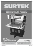
1
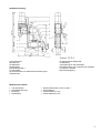
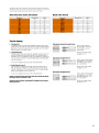
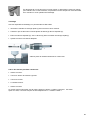
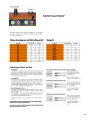
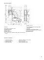
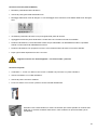
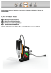
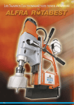
Bedienungsanleitung / Operation Manual / Mode d’emploi / Istruzioni per l’uso ALFRA ROTABEST 100 RL – E Metallkernbohrmaschine Metal Core Drilling Machine Perceuse ROTABEST à socle magnétique Carotatore a base elettromagnetica Artikel-Nr. 18634 / Prod.-No. 18634 / Réf. 18634 / N. articolo 18634 1 Inhaltsverzeichnis / Contents / Table des matières / Indice Sicherheitshinweise, Bestimmungsgemäße Verwendung, Technische Daten, Mitgeliefertes Zubehör, Gerätebeschreibung, Ein- und Ausschalten, Arbeiten mit Kernbohrer, Arbeiten mit Vollbohrer, Reinigen und Pflegen, Warten und Reparieren, EG-Konformitätserklärung, Explosionszeichnung, Ersatzteilliste Safety instructions, Specified Conditions of Use, Technical Data, Scope of supply, Description, Switching on and off, How to work with annular cutters, How to work with twist drills, Cleaning and care, Maintenance and repair, CE Declaration of conformity, Exploded drawing, Spare part list Consignes de sécurité, Conditions d’utilisation, Détails techniques, Accessoires fournis avec l’appareil, Description de l’appareil, Mise en marche et arrêt de la perceuse, Pour des travaux avec des fraises, Pour des travaux avec des forets hélicoïdaux, Nettoyage et entretien, Révision et réparation, Déclaration de Conformité CE, Vue éclatée, Nomenclature des pièces de rechange Avvertenze sulla sicurezza, Uso appropriato, Dati tecnici, Accessori forniti, Descrizione dell’apparecchio, Ascensione e spegnimento, Lavorare con punte cave, Lavorare con punte piene, Pulizia e cura, Manutenzione e riparazione, Dichiarazione di conformità CE, Vista esplosa, Lista dei ricambi Vor Inbetriebnahme lesen und aufbewahren! Seite 3 Please read and save these instructions! Page 12 À lire avant la mise en service puis à conserver ! Page 21 Leggere attentamente prima della messa in funzione e conservare! Pagina 30 2 Sicherheitshinweise Bei Bohren an Wänden und Decken muss die Metallkernbohrmaschine durch den mitgelieferten Sicherheitsgurt abgesichert werden. Die Magnethaftkraft bleibt bei einer Stromunterbrechung nicht erhalten. Der ausgebohrte Kern wird automatisch vom Auswerferstift ausgestoßen. Der Auswerferstift kann bei unsachgemäßer Handhabung brechen. Nur unbeschädigte Anschlussleitungen und Verlängerungsleitungen verwenden und regelmäßig auf Beschädigung überprüfen. Sonst besteht die Gefahr eines elektrischen Schlages. Netzspannung und Spannungsangaben am Gerät müssen übereinstimmen. Beim Arbeiten mit diesem Gerät folgende Schutzausrüstung tragen: Schutzbrille, festes Schuhwerk, Gehörschutz, Haarnetz (bei langen Haaren), Handschuhe, ggf. auch Schürze und Helm. Die Aufstellfläche für den Magnetfuß muss eben, sauber und rostfrei sein. Lack- und Spachtelschichten entfernen. Keine Elektro-Schweißarbeiten an dem Werkstück ausführen, auf dem die Metallkernbohrmaschine zum Einsatz kommt. Vor allen Arbeiten Kühlmitteleinrichtung zur Unterstützung der Kühlung montieren. Bestimmungsgemäße Verwendung Dieses Gerät ist bestimmt zum Bohren, von Materialien mit magnetisierbarer Oberfläche, mit Kernbohrern, Vollbohrern und zum Schneiden von Gewinden. Es ist bestimmt für den gewerblichen Einsatz in Industrie und Handwerk. Das Gerät lässt sich waagrecht, senkrecht und über Kopf einsetzen. 3 Technische Daten Art.-Nr.: 18634 Bezeichnung: ROTABEST 100 RL - E Leistungsaufnahme: 2500 Watt / 230 V Lastdrehzahl: 50-110/75-175/105-245/165-385 -min Werkzeugaufnahme: MK 3 Spannung: (je nach Typenschild) 230 V 50/60 Hz Magnethaftkraft: 20000 N Bohr Ø max. in Stahl: - Kernbohrer - Spiralbohrer 100 mm 32 mm Schnitttiefe: 50 mm Hubbereich: 245 mm Magnetfußgröße: 80 x 230 mm 2200 Watt / 110 V 1 110V 50/60Hz 4 Gerätebeschreibung A) Antriebsmotor B) Drehkreuz C) Bedienfeld D) Magnetfuß E) Bohrspindel MK 3 F) Tiefenskala G) Inbusschrauben für Hubbereichseinstellung des Antriebmotors H) Spannhebel für Magnetfuß I) Abstützung J) Aussparung für Sicherheitsgurt K) Stellschrauben zum Justieren des Schlittens L) Taster für Linkslauf M) Drehzahlregelung Mitgeliefertes Zubehör Transportkasten Kühlmitteleinrichtung Bohrspray Spänehaken Zahnkranzbohrfutter 3-16 mm, MK 3 Sicherheitsgurt Inbusschlüssel 2,5 mm Inbusschlüssel 6,0 mm 5 Ein- und Ausschalten Zuerst Kabel und Stecker auf Beschädigung prüfen. Die Taste MAGNET ON betätigen, damit der Magnet haftet und der Halt des Bohrständers gewährleistet wird. Für eine bessere Positionierung den Spannhebel lösen. Jetzt ist der Bohrständer 30° nach links oder rechts schwenkbar, bzw. 10 mm nach vorne und nach hinten zu verschieben. Für nicht magnetisierbare Materialien verwenden Sie bitte die ROTABEST Vacubest Vakuumanlage (Artikel - Nr. 18150). Bei Arbeiten an Wänden und Decken die Bohreinheit mit dem Sicherheitsgurt sichern. Wir empfehlen bei diesen Arbeiten das Kühlen durch ein Spray (ALFRA BIO 4000, Artikel Nr. 21040). Antriebsmotor durch Betätigen der Taste MOTOR ON einschalten. Das Ausschalten erfolgt in umgekehrter Reihenfolge MOTOR OFF und dann MAGNET OFF. MPI-System Bei Funktion „Magnet an“ stehen von Beginn an 100 % der Magnetleistung zur Verfügung. Gleichzeitig wird ein sogenanntes Zeitglied aktiviert, voreingestellt auf 60 Sekunden. Wird nach „Magnet an“ der Motor nicht zugeschalten, so blinkt die LED der Magnetschaltertaste auf der Folientastatur und es ertönt gleichzeitig ein Summton. Diese zeitgesteuerte Warnfunktion wird auch aktiviert, wenn nach dem Bohren und Abschalten des Motors der Magnet nicht abgeschaltet wird. Eine Funktionsprüfung der LED und des Summers wird durchgeführt, wenn die Maschine über das Stromkabel über das Stromnetz verbunden wird (kurzes LED Blinken und kurzer Summton). Damit kann man vor Ort schnell und einfach das verwendete Modell bzw. die verwendete Schaltung gegenprüfen. Die neuen Leiterplatten sind 100 % kompatibel mit Maschinen älterer Baureihen, d.h. im Reparaturfalle kann problemlos Ersatz bzw. Austausch erfolgen. Einstellen der Drehzahl Die Maschine verfügt über ein Getriebe mit vier mechanischen Getriebestufen und einer Vollwellenelektronik. Stellen Sie zuerst die richtige mechanische Einstellung ein und passen anschließend mit der elektronischen Drehzahlregulierung die genaue Drehzahl ein. Nach Möglichkeit immer die Einstellung mit niedriger Getriebeabstufung und hoher Motorendrehzahl wählen. Somit ist der Motor mit hohem Drehmoment eingestellt und vor Überhitzung bei starker Belastung geschützt. Thermoschutz Der Thermoschutz schaltet den Motor bei Überhitzung automatisch ab. Danach den Motor mit hoher Drehzahl im Leerlauf ca. 2 min. zum Abkühlen laufen lassen. 6 Arbeiten mit Kernbohrer (Weldonschaft) Werkzeughalter AMK 3 in Bohrspindel montieren Auswerferstift (Zentrierstift) durch den Kernbohrerkopf schieben. Montage der ALFRA ROTABEST Kernbohrer nach Zeichnung. Gewindestift muß Mitnehmerfläche am Kernbohrer mittig treffen. Fest anziehen. Zuerst den Kernbohrer mit Auswerferstift auf einen angekörnten Punkt oder Anriss ausrichten und aufsetzen. Den Kernbohrer aufsetzten und Werkstück anbohren bis die ganze Schnittfläche als Kreisring ausgebildet ist. Das Bohren mit ALFRA ROTABEST Kernbohrern erfordert keinen großen Kraftaufwand. Während des Bohrvorgangs sollte der Kernbohrer ständig gekühlt werden. Optimale Kühlung ist durch unsere Kühlmitteleinrichtung mittels Innenkühlung möglich. Während des Bohrens den Antriebsmotor nicht abschalten. Nach dem Bohrvorgang Kernbohrer bei laufendem Motor zurückziehen. Nach jedem Bohren Späne und Kern entfernen. Späne mit Spänehaken entfernen. Nicht mit bloßer Hand anfassen. Verletzungsgefahr! Arbeiten mit Vollbohrer Das Zahnkranzbohrfutter 3-16 mm mit MK 3 Schaft ist nur zum Bohren mit Spiralbohrern geeignet. Bohrfutter mit Adapter in die Bohrspindel einsetzen. Spiralbohrer in Bohrfutter einsetzen und mit Bohrfutterschlüssel fest spannen. Spiralbohrer mit MK 3 Schaft können direkt in die Bohrspindel eingesetzt werden. 7 Durch Lösen der Zylinderschrauben lässt sich der Antriebsmotor auf dem Schlitten stufenlos verstellen (für maximale Hubvergrößerung beim Einsatz mit Spiralbohrern, Bohrfuttern oder zum Gewindeschneiden). Gewindeschneiden Mit den Gewindeschneidschnellwechselfuttern besteht die Möglichkeit, Gewinde von M3 bis M 30 zu schneiden. Das Schnellwechselfutter (1) in die Bohrspindel der Maschine einführen. Auf festen Sitz achten. Anschließend Gewindebohrer (3) in Schnellwechseleinsatz (2) montieren. Jetzt den Schnellwechseleinsatz (2) mit Gewindebohrer (3) in Schneidfutter (1) einsetzen. Den Motor auf die entsprechende Schnittgeschwindigkeit einstellen. Beim Bohren darauf achten, dass der Gewindebohrer auf dem Kernloch aufgesetzt wird. Bei Beendigung der Vorwärtsbewegung wie folgt vorgehen: Den Motor ausschalten. Taster Linkslauf betätigen. Motor anschalten. Den Gewindebohrer zurückführen. Den Motor ausschalten. Der Motor dreht nur in Linksrichtung nach Betätigung des Tasters Linkslauf. D. h. nach Anhalten des Motors wird immer automatisch der Rechtslauf aktiviert. 8 9 Reinigen und Pflegen Vor Pflegearbeiten immer zuerst den Netzstecker ziehen, sonst droht Verletzungsgefahr durch unbeabsichtigtes Einschalten der Maschine. Motorraum von außen mit trockener Druckluft ausblasen. Anschlussleitungen auf Beschädigungen kontrollieren. Alle Gleitflächen regelmäßig reinigen und ölen. Sollte sich trotzdem durch Abnutzung an der Schwalbenschwanzführung Seitenspiel einstellen, kann dies durch Nachstellen von seitlich angebrachten Gewindestiften (K) ausgeglichen werden. Nach ca. 250 Betriebsstunden sollten die Kohlebürsten ausgetauscht werden. Nach Arbeitsbeendigung empfehlen wir, die Metallkernbohrmaschine in dem Transportkoffer liegend aufzubewahren. Warten und Reparieren Warten, prüfen und reparieren dürfen nur Elektrofachkräfte nach den im jeweiligen Land gültigen Vorschriften. Nur Original ALFRA Ersatzteile verwenden. Ersatzteilübersicht am Ende dieser Bedienungsanleitung. Die Metallkernbohrmaschinen ALFRA ROTABEST sollten nach ca. 250 Betriebs-stunden von unserer ALFRA Werkstatt oder Vertragspartnern gewartet werden. Das Getriebeöl Lubcon Turmogearoil PE 150 300 ml sollte ebenso wie die Kohlebürsten erneuert werden. 10 EG-Konformitätserklärung Hiermit erklären wir, Alfred Raith GmbH 2. Industriestr. 10 68766 Hockenheim dass die Metallkernbohrmaschine ALFRA Rotabest 100RL-E folgenden Richtlinien entspricht: Maschinenrichtlinie: 2006/42/EG Niederspannungsrichtlinie: 2006/95/EG Elektromagnetische Verträglichkeit (EMV): 2004/108/EG RoHs-Richtlinie: 2011/65/EU Folgende Normen oder normative Dokumente wurden angewandt: Maschinenrichtlinie: EN 12348:2000+A1:2009 EN 61029-1:2009 Niederspannungsrichtlinie: EN 60204-1:2006+A1:2009 EN 60034-1:2010 EN 60034-5:2001+A1:2007 EMV- Richtlinie: EN 55014-1:2006+A1:2009+A2:2011 EN 55014-2:1997+A1:2001+A2:2008 EN 61000-3-2:2006+A1:2009+A2:2009 EN 61000-3-3:2008 RoHs-Richtlinie: EN 50581:2012 Bevollmächtigt für die Zusammenstellung der Unterlagen: Alfred Raith GmbH 2. Industriestr. 10 68766 Hockenheim, DE Hockenheim, 18.06.2013 Markus A. Döring (Geschäftsführer) 11 Safety instructions During drilling operations on walls and ceilings, the Metal Core Drilling Machine must be safeguarded with the included safety belt. The magnetic adhesion is not maintained in case of a failure of circuit. The cut core will be ejected automatically by the ejector pin. The ejector pin could possibly break in case of improper use. Only use undamaged power cord and extension cords and regularly check on damages. Danger of an electric shock! Power supply and voltage details at the device must correspond. When working with this device, wear the following protection equipment: Safety goggles, appropriate footwear, ear protection, hair net (for long hair), gloves, possibly also apron and safety helmet. The place of installation for the magnet foot must be clean and rustfree. Remove lacquer and filler. Do not execute any electric welding on the workpiece on which the Metal Core Drilling Machine is used. Prior to all operations mount coolant unit. Specified conditions of use This device is destined to cut material with magnetisable surface with core cutters, twist drills and to tap threads in sheltered environment for commercial use industry and craft. The device is suitable for drilling vertical, horizontal and overhead. 12 Technical Data Prod.-No.: 18634 Name: ROTABEST 100 RL-E Input: 2500 Watt / 230 V Load RPM: 50-110/75-175/105-245/165-385 RPM Tool Holder: MT 3 Voltage: (see nameplate) 230 V 50/60 Hz Magnetic Adhesion: 20000 N Boring Ø max. in steel: - Core Drills - Twist Drills 100 mm 32 mm Cutting Depth: 50 mm Stroke: 245 mm Size of Magnet Foot: 80 x 230 mm 2200 Watt / 110 V 110V 50/60Hz 13 Description A) Motor B) Spindle C) Control panel D) Magnet foot E) Arbor MK3 F) Depth scale G) Hexagon screw for the adjustment of the motors stroke range H) Clamping lever for clamping the magnet foot I) Rear support J) Recess for safety belt K) Adjusting screws for adjusting the slide L) Push button for left hand rotation M) Rotation speed control Mitgeliefertes Zubehör Transport case Coolant unit Coolant spray Safety belt Chip remover Drill chuck 3-16 mm, MK 3 Inbusschlüssel 2,5 mm Inbusschlüssel 6,0 mm 14 Switching on and off Check connecting line and plug on damages first. Push button MAGNET ON, in order to initiate the magnet and the magnetic adhesion is guaranteed. For better positioning loosen the clamping lever. Now the drill base can be pivoted 30° to the left or to the right, respectively it can be slid 10 mm forwards or backwards. For non-magnetizable materials, please use the ROTABEST Vacubest (Prod.-No. 18150). When working on walls and ceilings, secure machine with safety belt. For these operations we recommend cooling with our spray ALFRA BIO 4000, Prod.- No. 21040. Push the button MOTOR ON to start the Motor. To switch off the machine proceed in reverse order, first MOTOR OFF, then MAGNET OFF. MPI-System At function „magnet on“, 100% of the mangnet power is available right from the beginning. Simultaneously a timing relay will be activated which is preset to 60 seconds. If the motor will not be switched on after “magnet on” the LED of the magnet switch on the key pad is flashing and a buzzer sounds at the same time. This time-controlled alarm will be also activated after drilling is done and the motor is switched off but the magnet is still on. A functional check of the LED and of the buzzer is carried out if the machine will be connected to the mains with the electric cable (short flashing of the LED and short buzzing). With it it it’s possible to test the model in use respectively the control in use fast and easily on site. The new PCBs are 100% compatible with machines of older type series, i.e. in case of repair they can be replaced respectively exchanged without problems. Adjustment of the rotation speed The machine has one gear with 4 mechanical reduction stages and a full-wave electronic. At first you need to adjust the correct mechanical adjustment. Afterwards you need to adapt the rotation speed with the help of the electrical rotation speed regulator. If it’s possible always choose the adjustment with low gear shifting and high engine speed. Then the motor is set at a high torque and therefore it’s protected against overheating due to high load. Thermo protection The thermo protection stops the motor when it’s overheated automatically. Afterwards you need to let it run with a high rotation speed at the idle speed for about two minutes. 15 How to work with annular cutters (Weldon shank) Mount Tool Holder AMK 3 in arbor. Push ejector pin (center pin) through head of annular cutter. Mounting of ROTABEST cutter according to drawing. The setscrew must be positioned in the center of the lateral flat side of the Weldon shank. Fix tightly. First place annular cutter with ejector pin on a marked center or marking. Spot-drill until the entire cut edge is formed as a circle. Drilling with ALFRA ROTABEST cutters does not require much expenditure of force. During the drilling process the cutter should be cooled permanently. Optimal Cooling is possible by internal cooling with our coolant unit. Do not stop the motor during the drilling process. After the process draw the cutter back with running motor. Remove chips and core after each drilling. Remove chips with chip-remover. Do not touch with bare hands. Danger of injury! How to work with twist drills The drill chuck 3-16 mm with MT 3 shank is only to be used with twist drills. Insert drill chuck with adaptor in the arbor. Insert twist drill in drill chuck and tighten drill chuck key. Twist drills with MT 3 shank can be inserted directly into the arbor. 16 The motor can be continuously adjusted on the slide by releasing the Allan screw (for a maximum enlargement of the stroke when using twist drills, drill chucks and tapping attachments). Tapping With the Quick Change Tapping Adaptor, there is the possibility to tap threads from M3 up to M 30. Insert the Quick Change tapping Adaptor (1) in the arbor of the machine. Pay attention to a tight fit. Subsequently mount the tap (3) in the tap collet (2). Now insert the tap collet (2) with tap (3) in the Quick Change Tapping Adaptor (1). Adjust the motor to the corresponding cutting speed. It must be ensured that the tap is placed on the drill hole. When stopping the forward motion proceed as follows: Switch off motor. Push button „Left-hand rotation“. Switch on motor. Lead back the tap. Switch off the motor after tap is completely led back. Left–hand rotation is only activated when corresponding button was pushed which means that after stopping the motor automatically the right–hand rotation is activated. Speed Control Left-hand rotation 17 18 Cleaning and care Pull plug prior to cleaning to avoid injuries by unintentional switching on. Clean the outside of the motor with dry compressed air. Check connecting lines on damages. Clean and grease sliding surfaces regularly. Should lateral play arise by wear of the dovetail guide this can be adjusted by adjusting the laterally positioned set screws (K). Carbon brushes should be replaced after appr. 250 hours running time. After the work is finished we recommend to store the Metal Core Drilling Machine in the transport case in a lying position. Maintenance and repair Maintenance, check and repairs are only to be made by electronics specialists according to the valid regulations of the respective country. Only use genuine ALFRA spare parts. Spare part list at the end of this operation manual. The Metal Core Drilling Machine ALFRA ROTABEST should be serviced after appr. 250 hours running time by our ALFRA workshop or appointed dealers. The gear oil (Lubcon, Turmogearoil PE 150 300ml) should be exchanged as well as the brushes. 19 CE Declaration of Conformity Herewith we Alfred Raith GmbH 2. Industriestr. 10 68766 Hockenheim declare that the metal core drilling machine ALFRA Rotabest 100RL-E corresponds to the following standards: Machine standard: 2006/42/EG Low-voltage standard: 2006/95/EG Electro-magnetic compatibility (EMC): 2004/108/EG RoHs-standard: 2011/65/EU Following standards or standard documents were applied: Machine standard: EN 12348:2000+A1:2009 EN 61029-1:2009 Low-voltage standard: EN 60204-1:2006+A1:2009 EN 60034-1:2010 EN 60034-5:2001+A1:2007 EMC-standard: EN 55014-1:2006+A1:2009+A2:2011 EN 55014-2:1997+A1:2001+A2:2008 EN 61000-3-2:2006+A1:2009+A2:2009 EN 61000-3-3:2008 RoHs-standard: EN 50581:2012 Authorized for the compilation of the documents: Alfred Raith GmbH 2. Industriestr. 10 68766 Hockenheim, DE Hockenheim, 18.06.2013 Markus A. Döring (Managing Director) 20 Consignes de sécurité Pendant des opérations de perçage de murs ou de plafonds, l’appareil doit impérativement être maintenu avec la courroie de sécurité fournie avec la machine car l’appareil perd son dhérence magnétique dès que l’alimentation en courant est interrompue. Le noyau est libéré automatiquement par la tige d’éjection. Si la tige est mal utilisée, elle peut casser. Assurez vous que les fiches, prises et fils électriques que vous utilisez sont en bon état. Vérifiez les régulièrement. Danger d’électrocution! La tension du réseau d’alimentation électrique doit être identique avec celle de la machine. Pendant les travaux avec cette machine, nous recommandons à leurs utilisateurs de porter des lunettes de sécurité, des chaussures adéquates, une protection acoustique, une protection pour les cheveux (surtout s’ils sont longs), gants, un casque et une blouse de travail. La surface de l’élément où le socle magnétique sera posé doit être plane, propre, sans rouille. Eliminez les couches de peinture ou de mastic auparavant. N’effectuez en aucun cas des travaux d’électro-soudure sur l’élément sur lequel la perceuse sera employée. Avant tous travaux fixer le dispositif de lubrification pour que le refroidissement soit assuré. Conditions d’utilisation Cet appareil est conçu pour des travaux de caractère industriel ou artisanal pour percer des trous dans des matériaux dont la surface est magnétisable avec des fraises à carotter et des forets et pour procéder à des opérations de taraudage.Il peut être utilisé horizontalement, verticalement ou à bras levés. 21 Détails techniques Numéro d’article: 18634 Description: ROTABEST 100 RL-E Puissance: 2500 Watt / 230 V Vitesse sous charge: 50-110/75-175/105-245/165-385 -min Porte-outil: MK 3 Tension: (se référer à la plaque de fabrication) 230 V 50/60 Hz Adhérence magnétique: 20000 N 2200 Watt / 110 V 1 110V 50/60Hz Diamètre de percage maximum dans l’acier: - fraise à carotter - foret helicoidal 100 mm 32 mm Profondeur de coupe: 50 mm Course: 245 mm Dimensions du socle magnétique: 80 x 230 mm 22 Description A) B) C) D) E) F) G) Moteur de commande Tourniquet Tableau de commande Socle magnétique Broche de perçage MK 3 Graduation de profondeur Vis à 6 pans creux pour le réglage de course du moteur H) I) J) K) L) M) Levier de serrage du socle magnétique Èlement d’appui postérieur Passe pour la courroie de sécurité Vis d’ajustage du glissoir Touche pour la rotation à gauche Régulation de vitesse Accessoires fournis avec l’appareil Malette de transport Bombe de lubrifiant Dispositif de lubrification Crochet pour retirer les copeaux Mandrin de couronne dentée 3-16 mm, MK 3 Courroie de sécurité Clé pour vis à 6 pans creux 2,5 mm Clé pour vis à 6 pans creux 6,0 mm 23 Mise en marche et arrêt de la perceuse Aimant Moteur Assurez vous du bon état des fiches, prises et fils électriques ! Appuyez sur la touche MAGNET ON (Aimant) pour que le socle adhère et que la stabilité de l’appareil soit garantie. Pour un meilleur positionnement relâcher le levier de serrage (H). On peut alors incliner le socle magnétique de 30° vers la gauche ou la droite, également l’avancer ou le reculer de 10 mm. Si vous travailler des matériaux non magnétisables, utilisez notre système à vide ROTABEST Vacubest (article 18150). Pour des travaux sur murs et plafonds, attachez la perceuse avec la courroie de sécurité. Pour des travaux sur murs ou plafonds nous conseillons le refroidissement avec une bombe de lubrifiant ALFRA BIO 4000 - article 21040. Mettez le moteur en marche avec la touche MOTOR ON. La mise an arrêt se fait alors dans le sens contraire, c’est-à-dire d’abord MOTOR OFF puis MAGNET OFF. Système MPI La fonction « Aimant activé » permet d'exploiter la puissance de l'aimant à 100 % dès le départ. Simultanément, un relais dit de temporisation est activé avec un préréglage de 60 secondes. Si le moteur n'est pas mis en marche après activation de la fonction « Aimant activé », la DEL de la touche de commutateur magnétique s'allume sur le clavier à effleurement et un signal sonore retentit simultanément. Cette fonction d'avertissement temporisée est également activée lorsque l'aimant n'est pas désactivé après le perçage et la mise hors tension du moteur. Le système effectue un contrôle du fonctionnement des DEL et du ronfleur lorsque le câble de la machine est branché sur l'alimentation secteur (clignotement bref de la DEL et signal sonore bref). Ceci permet d'effectuer sur place un contrôle rapide et simple du modèle et du circuit qui sont utilisés. Les nouveaux circuits imprimés sont 100 % compatibles avec la série de machines anciennes. En cas de réparation, le remplacement ou l'échange ne posent aucun problème. Réglage de la vitesse La machine dispose d’un engrenage à deux vitesses mécaniques et d’un système électronique à onde pleine. Ajustez tout d’abord la fonction mécanique et réglez ensuite la vitesse nécessaire à l’aide de la touche de régulation de vitesse. Choisir dans la mesure du possible un réglage de l’engrenage à basse vitesse et une vitesse élevée du moteur. Ainsi celui-ci est réglé à une vitesse élevée et protégé contre un surchauffement en cas de haute sollicitation. Protection thermique La protection thermique arrête le moteur automatiquement en cas de surchauffement. Faire ensuite tourner le moteur en marche à vide à vitesse élevée pendant environ 2 minutes pour qu’il refroidisse. 24 Pour des travaux avec des fraises (à tige Weldon) Enclencher le porte-outil AMK 3 dans la broche de perçage. Passer la pointe de centrage (tige d’éjection) à travers la tête de la fraise. Introduire la fraise ROTABEST selon le schéma. Veiller à placer le piton au centre de la surface plane de la tige de la fraise. Serer. Tout d’abord placer la fraise avec la pointe de centrage et la tige d’éjection sur un point déjà amorcé au pointeau ou fissuré. Placer la fraise et percer la pièce de travail jusqu’à ce que toute la surface à couper soit amorcée. Le perçage avec les fraises ALFRA ROTABEST ne demande pas d’efforts particuliers. Pendant le perçage la fraise doit être continuellement refroidie. Un refroidissement optimal est assuré avec le dispositif de lubrification par refroidissement intérieur. Ne pas arrêter le moteur pendant le perçage. Une fois le perçage terminé, retirez la fraise pendant que le moteur est encore en marche. Après chaque opération de perçage, enlever le noyau et les copeaux. Retirez les copeaux avec le crochet fourni avec la machine. Ne jamais essayer de les enlever avec les doigts. Danger de blessure! Travaux avec des forets Le mandrin à couronne dentée 3-16 mm avec une tige MK3 est uniquement adéquat pour percer avec des forets hélicoïdaux. Ajuster le mandrin avec l’adaptateur dans la broche de perçage. Ajuster le foret dans le mandrin et le fixer avec la clé. Les forets hélicoïdaux à tige MK3 peuvent ètre fixés directement dans la broche de perçage 25 En désserrant la vis à 6 pans creux on peut monter ou descendre le moteur à volonté pour atteindre une course maximum, en particulier lors de l’emploi d’un foret hélicoïdal, d’un mandrin ou d’une opération de taraudage. Taraudage Avec les dispositifs de taraudage, on peut tarauder de M3 à M22. Introduire le mandrin de serrage rapide (1) dans la broche de la machine. S’assurer qu’il est bien serré. Ensuite ajuster le taraud (3) dans le dispositif (2). Enfin introduire le dispositif (2) avec le taraud (3) dans le mandrin de serrage rapide(1). Ajuster le moteur à la vitesse adéquate. Veiller à placer le taraud exactement sur l’avant-trou. A la fin des travaux procéder comme suit: Arrêter le moteur. Tourner le bouton de rotation à gauche. Tourner le moteur. Le taraud remonte. Arrêter le moteur Le moteur tourne uniquement vers la gauche lorsque le bouton « rotation à gauche » est activé. Après son arrêt, il se remet toujours et automatiquement en « rotation à droite » 26 Drehzahlregler = compte-tours Linkslauf = rotation à gauche 27 Nettoyage et entretien Débranchez l’appareil avant tout nettoyage de l’appareil. Dépoussiérer la partie extérieure du moteur à l’air comprimé. Contrôler l’état du fil d’alimentation électrique. Nettoyez et lubrifiez régulièrement les surfaces lisses. Si par l’usure on observe un certain jeu latéral, on peut y remédier en ajustant les vis sans tête (K) situées sur le coté. Les charbons doivent être changés après environ 250 heures d’emploi de la machine. Nous recommandons de stocker la perceuse dans la malette de transport en position horizontale après l’emploi. Révision et réparation Seuls les spécialistes sont aptes à contrôler, réviser ou réparer ces appareils. Des réparations faites de façon impropre peuvent causer des dommages et dangers considérables pour leurs utilisateurs. Utilisez exclusivement les pièces de rechange de la marque ALFRA. Liste des pièce détachées à la fin de ce manuel. Après environ 250 heures de travail les perceuses ALFRA ROTABEST doivent être révisées à l’atelier ALFRA ou par un atelier agréé par ALFRA. L'huile de boîte de vitesse (Lubcon, Turmogearoil PE 150 300 ml) ainsi que les charbons devraient être renouvelés. 28 Déclaration de Conformité CE Nous Alfred Raith GmbH 2. Industriestr. 10 D - 68766 Hockenheim déclarons que la perceuse ALFRA Rotabest 100RL-E correspond aux recommandations suivantes : Recommandations de la machine: 2006/42/EG Recommandations de la basse tension: 2006/95/EG Compatibilité électromagnétique: 2004/108/EG Recommandations de la RoHs: 2011/65/EU Les normes ou documents normatifs suivants ont été appliqués: Recommandations de la machine: EN 12348:2000+A1:2009 EN 61029-1:2009 Recommandations de la basse tension: EN 60204-1:2006+A1:2009 EN 60034-1:2010 EN 60034-5:2001+A1:2007 Compatibilité électromagnétique: EN 55014-1:2006+A1:2009+A2:2011 EN 55014-2:1997+A1:2001+A2:2008 EN 61000-3-2:2006+A1:2009+A2:2009 EN 61000-3-3:2008 Recommandations de la RoHs: EN 50581:2012 Autorisé pour l’élaboration des documents: Alfred Raith GmbH 2. Industriestr. 10 68766 Hockenheim, DE Hockenheim, 18.06.2013 Markus A. Döring (Directeur) 29 Indicazioni di sicurezza Per forare in verticale e capovolto, il trapano deve essere fissato mediante la cintura di sicurezza in dotazione. La forza magnetica è disattivata in caso d’interruzione di corrente. Il nocciolo forato viene espulso automaticamente dall’espulsore. Attenzione! La punta guida si può rompere se maneggiata senza cura. Utilizzare esclusivamente prese e prolunghe non danneggiate e verifcare regolarmente lo stato delle stesse. La tensione di corrente deve essere la stessa del trapano. Indossare i seguenti indumenti di sicurezza per lavorare con questo apparecchio: occhiali di sicurezza, scarpe antinfortunistiche, protezioni per orecchie, rete per i capelli (con capelli lunghi), guanti, ed eventualmente anche casco e grembiule. La superficie d’appoggio della base magnetica deve essere piana, pulita e senza ruggine. Rimuovere vernici ed altre sostanze. Non effettuare saldature sul pezzo in cui viene fissato il trapano. Prima di effettuare qualunque lavoro, montare il sistema di raffreddamento. Condizioni di utilizzo dell’apparecchio Utilizzare in luoghi chiusi, nell’industria e nell’artigianato, per forare con frese e punte e per filettare con maschi, materiali con una superficie magnetizzabile. L’apparecchio si può utilizzare in posizione orizzontale, verticale e capovolto. 30 Dati tecnici Articolo: 18634 Modello: ROTABEST 100 RL - E Potenza assorbita in Watt: 2500 Watt / 230 V Velocità giri/min.: 50-110 / 75-175 / 105-245 / 165-385¹-min Attacco utensile: Cono Morse 3 Alimentazione: 230 V 50/60 Hz Forza elettromagnetica: 20000 N Ø max. foratura in acciaio: - Frese - Punte 100 mm 32 mm Profondità max. foratura per frese: 50 mm Corsa: 245 mm Base magnetica: 80 x 230 mm 2200 Watt / 110 V 110V 50/60 Hz 31 Descrizione trapano A) Motore B) Dispositivo di regolazione corsa C) Pannello di controllo D) Base magnetica E) Attacco CM3 F) Scala di escursione G) Vite esagonale per regolazione della guida di scorrimento del motore H) Leva posizionamento e bloccaggio della base magnetica I) Appoggio J) Passaggio per cintura di sicurezza K) Viti per il posizionamento della cremagliera L) Tasto giro a sinistra M) Regolatore di giri Accessori in dotazione Cassetta di trasporto Dispositivo refrigerante Refrigerante spray Gancio per truccioli Mandrino imbiettato 3-16 mm, MK 3 Cintura di sicurezza Chiave esagonale 2,5 mm Chiave esagonale 6,0 mm 32 Accensione e spegnimento Controlla la rete elettrica e le spine prima di creare Danni. Premi il pulsante MAGNET ON per iniziare ad attivare il magnete e per verificare l’adesione magnetica. Per migliorare il posizionamento della macchina allentare la leva di bloccaggio. Ora la base del trapano può essere ruotata di 30° a sinistra o destra, rispettivamente può essere fatta scorrere di 10 mm avanti e indietro. Per materiali non magnetizzabili, utilizzare ROTABEST Vacubest (codice prodotto 18150). Quando si lavora su pareti o soffitti, assicurare la macchina con la cintura di sicurezza. Per queste operazioni consigliamo di raffreddare con lo spray ALFRA BIO 4000 (codice prodotto 21040). Premere il pulsante MOTOR ON per azionare il motore. Per spegnere la macchina procedere in senso inverso, prima premere il pulsante MOTOR OFF, poi il pulsante MAGNET OFF. Sistema MPI All’accensione del pulsante “MAGNET ON” il 100% della potenza del magnete è disponibile fin da subito. Contemporaneamente un temporizzatore preimpostato a 60 secondi si attiva. Se il motore non si attiva dopo aver premuto il pulsante “MAGNET ON” il LED (indicatore della adesione magnetica) comincia a lampeggiare e nello stesso tempo si attiva anche un segnalatore acustico. Questo controllo sonoro a tempo si attiva anche dopo aver forato e il motore è spento ma il magnete è ancora acceso. Un controllo funzionale del LED e del suono può essere fatto se si collega la macchina alla presa elettrica con il cavo elettrico (si attiva un lieve lampeggiamento del LED e viene emesso un breve segnale sonoro). In questo modo si può testare il modello in modo facile e veloce sul posto. Le nuove schede elettroniche sono al 100% compatibili con tutte le macchine delle serie più vecchie, e quindi in caso di riparazione di queste ultime possono essere sostituite con queste nuove senza nessun problema. Regolazione della velocità di rotazione La macchina ha una sola coppia conica con 4 marce e un controllo ad onda piena. Per prima cosa è necessario trovare la corretta regolazione meccanica. Poi occorre adattare la velocità di rotazione con l’ausilio del regolatore di velocità. E’ possibile sempre scegliere la regolazione a basso cambio marcia e alto numero di giri del motore. In questo modo il motore viene regolato ad alta tensione e perciò viene protetto contro surriscaldamento da sovratensione. Protezione termica Dopodichè occorre lasciare che il motore funzioni al minimo per circa due minuti. La protezione termica arresta il motore automaticamente quando vi è surriscaldamento del motore. 33 Lavorare con frese (attacco Weldon) Montare il portautensili CM3 nell’attacco Inserire la punta guida nella testa della fresa Montaggio della fresa come da disegno. La vite di fissaggio deve centrare la cava Weldon della fresa. Stringere forte. Innanzitutto posizionare la fresa con la punta guida sulla parte da lavorare. Appoggiare le fresa sul pezzo da lavorare e forare finché si é formato un anello sul materiale. Durante la lavorazione, la fresa dovrebbe essere sempre raffreddata. Un raffreddamento ottimo é possibile tramite il nostro sistema di raffreddamento interno. Durante la lavorazione non spegnere il motore. A fine foratura estrarre la fresa con il motore azionato. Dopo ogni foratura asportare il truciolo e nocciolo. Togliere il truciolo con utensili appositi – non a mani nude – pericolo! Lavorare con punta Il mandrino 3 – 16 mm con attacco cono morse 3 é adatto solo per forare con punte cilindriche. Inserire il mandrino con il CM3 nell’attacco. Inserire la punta e serrare il mandrino. Punte con attacco cono morse 3 possono essere montate direttamente. Svitando la vite a testa cilindrica, il motore di comando può essere spostato in continuo sulla slitta (per un aumento massimo della corsa in caso di utilizzo con punte elicoidali e pinze portapunta). 34 Maschiare Con il mandrino a cambio rapido si ha la possibilità di filettare da M3 fino a M22. Inserire il mandrino (1) nell’attacco della macchina. Assicurasi della presa. Successivamente montare il maschio (3) nell'innesto a cambio rapido (2) e inserirlo nel mandrino. Impostare il motore alla velocità richiesta per la lavorazione. Nel filettare, prestare particolare attenzione che il maschio sia centrato sul foro. A fine rotazione in avanti procedere come segue: Spegnere il motore, premere il tasto d’inversione – ora il maschio può essere estratto dal foro, quindi spegnere il motore. Il motore gira a sinistra solamente dopo aver premuto il tasto giro a sinistra. Dopo avere spento il motore, viene attivato automaticamente sempre la rotazione a destra. 35 Maschiatura Maschi a macchina: il maschio da utilizzare si deve scegliere in base al foro da filettare. Seguire le seguente tabella ISO per la scelta giusta. Tabella fori metrica per filetti ISO Misura Passo Ø preforo M3 0,5 2,9 M4 0,7 3,3 M5 0,8 4,2 M6 1 5 M8 1,25 6,8 M10 1,5 8,5 M12 1,75 10,2 M14 2 12 M16 2 14 M18 2,5 15,5 M20 2,5 17,5 Passo fine Misura M8x1 M10x1 M12x1 M12x1,5 M14x1 M14x1,5 M16x1 M16x1,5 M20x1 M20x1,5 Passo 1 1 1 1,5 1 1,5 1 1,5 1 1,5 Ø preforo 7 9 11 10,5 13 12,5 15 14,5 19 18,5 Maschiatura Valori consigliati (tolleranze secondo ISO 2 6H) Valori consigliati per l’impiego di maschi a macchina con maschiatrici su trapani con base magnetica 1. Foro passante Per fori passanti consigliamo i maschi descritti a fianco che spingono il truciolo verso l’uscita del foro. Il particolare taglio assicura un inserimento sicuro quando si estrae il maschio con rotazione sinistra. Espulsione truciolo verso il basso 2. Foro cieco Espulsione truciolo verso l’alto Per fori ciechi consigliamo i maschi descritti a fianco. Il truciolo viene espulso dal foro in direzione opposta al senso di taglio. E’ importante che il maschio non giunga a fine corsa, affinché l’espulsione automatica venga garantita. E’ importante calcolare un preforo più profondo. Se non si rispetta questo particolare si deve estrarre il maschio manualmente 3. Foro cieco fino a 1,5 x D Espulsione truciolo verso l’alto Si adattano anche i maschi DIN 371 con gambo rinforzato forma B, con imbocco 3,5 fino a 5 filetti DIN 376 con gambo maggiorato, profondità filetto 3xD DIN 371 a scana- lature a spirale con gambo rinforzato, spirale destra a 35°, Forma punta C, ca. 3 filetti DIN 376 con gambo maggiorato, profondità filetto 2,5xD 36 raffigurati a fianco.Il truciolo viene espulso dal foro in direzione opposta al senso di taglio. E’ importante che il maschio non giunga a fine corsa, affinché l’espulsione automatica venga garantita. E’ importante calcolare un preforo più profondo. DIN 371 con gambo rinforzato, scanalatura destra a 17°, Forma punta C Ca. 2 fino 3 filetti DIN 376 con gambo maggiorato, profondit à filetto 2,5 x D Se non si rispetta questo particolare si deve estrarre il maschio manualmente Oltre ai maschi con attacco rinforzato, si possono utilizzare maschi DIN 376. Utilizzre sempre liquido refrigerante a sufficienza seguendo le direttive dei produttori di maschi. Pulizia e cura Prima dei lavori di manutenzione e cura staccare sempre la spina. In caso contrario esiste il pericolo di lesioni dovute a un inserimento involontario della macchina. Pulire dall’esterno il vano motore con aria compressa asciutta. Controllare se le linee di collegamento sono danneggiate. Pulire e oliare regolarmente tutte le superfici di scorrimento. Le spazzole di carbone dovrebbero essere sostituite dopo ca. 250 ore di funzionamento. Al termine dei lavori consigliamo di custodire orizzontalmente il carotatore a base elettromagnetica nella valigia di trasporto. Manutenzione e riparazione I lavori di manutenzione, riparazione e controllo devono essere eseguiti solo da elettricisti specializzati in conformità con le norme vigenti nel relativo Paese. Usare solo ricambi originali ALFRA. Elenco dei ricambi alla fine di queste istruzioni per l’uso. Dopo ca. 250 ore di funzionamento, i carotatori AlfraRotabest dovrebbero essere sottoposti a manutenzione presso la nostra officina AlFRA o altri partner contrattuali. Anche l’olio per ingranaggi (Lubcon, Turmogearoil PE 150 300 ml) dovrebbe essere cambiato come le spazzole di carbone. 37 Dichiarazione di conformità CE Con la presente noi, la Alfred Raith GmbH 2. Industriestr. 10 D-68766 Hockenheim dichiariamo che il carotatore a base elettromagnetica ALFRA Rotabest 100RL- E è conforme alle seguenti direttive: direttiva sulle macchine: 2006/42/CE direttiva sulla bassa tensione: 2006/95/CE compatibilità elettromagnetica (CEM): 2004/108/CE direttiva sulle RoHs: 2011/65/EU Sono stati applicati le seguente norme o documenti normativi: direttiva sulle macchine: EN 12348:2000+A1:2009 EN 61029-1:2009 direttiva sulla bassa tensione: EN 60204-1:2006+A1:2009 EN 60034-1:2010 EN 60034-5:2001+A1:2007 direttiva CEM: EN 55014-1:2006+A1:2009+A2:2011 EN 55014-2:1997+A1:2001+A2:2008 EN 61000-3-2:2006+A1:2009+A2:2009 EN 61000-3-3:2008 direttiva sulle RoHs: EN 50581:2012 Autorizzato alla compilazione dei documenti: Alfred Raith GmbH 2. Industriestr. 10 68766 Hockenheim, DE Hockenheim, 18.06.2013 Markus A. Döring (Amministratore delegato) 38 Ersatzteile / Spare Parts / Pièces de rechange 39 Pos. Stck. Art.-Nr. Beschreibung Description Description 1 2 3 3 5 6 7 8 9 10 11 12 13 1 1 1 1 1 1 3 2 1 2 1 1 1 189852110 189852101 189412127.230V 189412127.110V 189501072 189852102 189601074 189852103 189852115.100RLE 189501076 189601101 189501078 189501084 Ständergehäuse Schlitten Magnetfuß 230 V (kompl.) Magnetfuß 110 V (kompl.) Ritzelwelle Zahnstange Speichen kpl. Mess.Führungsschiene Typenschild R100 Befestigungsstein Flanschstück Schieber Rahmendichtung housing slide magnetic base 230V magnetic base 110V pinion shaft rack spoke brass guide rail, type plate R100 motor fixing part flange piece slide frame seal 14 15 16 17 1 1 1 1 Schild (Sicherheitshinweis) Rändelmutter Stütze Linsenkopfschraube plate (safety instructions) knurled nut support lens head screw 18 5 Flachrundschraube mushroom head screw vis à tête plate 19 5 14 set screw -Tuflokhexagon socket screw M5x12 21 1 Gewindestifte -TuflokInbusschrauben M5x12 DIN 6912 Gewindestifte DIN 913 M5x16 vis filetée sans tête -Tuflok- 20 set screw DIN 913 M5x10 vis filetée sans tête M5 x 16 22 1 189480001A 189301079 189852105 DIN7500-M4X10 ISO7380-M4X1010.9 DIN913-M5X1045H-TF DIN6912-M5X128.8 DIN913-M5X1645H DIN915-M5X1645H chassis glissoir socle magnétique 230V socle magnétique 110V arbre de pignon crémaillère moyeux lardon de glissière, plaque de fabrication R100 fixation pour le moteur raccord à bride coulissoir joint d'assemblage plaquette de conseils de sécurité écrou moleté support vis à tête goutte-de-suif Gewindestift DIN 915 M5x16 vis filetée sans tête M5 x 16 23 6 DIN912-M6x20-8.8 24 25 26 27 28 29 30 2 1 4 1 1 2 1 hexagon socket screw knurled nut tapping screw 5,5 x 16mm lock washer washer plain bearing resilient thrust piece vis à tête DIN 912 M8x80 écrou moleté vis 5,5 x 16 mm clip d'arrêt 19 mm rondelle palier lisse membre de pression à ressorts 31 33 34 35 36 37 38 39 40 41 42 4 2 1 1 2 1 1 1 9 2 1 DIN912-M8X80-8.8 189601079 DIN7981-M5,5X16 DIN6799-D19,0 DIN988-25X35X2,0 189490503 189301080 DIN913-M12X1045H 189601096 189412071 189490604 189490605 189301081 189490608 189480010 DIN1476-M2,0X5,0 189160416 189491010 Inbusschrauben M5x40 Inbusschrauben DIN 912 M8x80 Rändelmutter Blechschrauben 5,5 x 16 Sicherungsscheibe 19 mm Passscheiben Gleitlager Federndes Druckstück set screw DIN 915 M5x16 hexagon socket screw M5 x 40 set screw knurled screw supply cable 230 V protection sleeve threaded joint flexible cable guiding seal scale grooved drive stud dowel pin 4x16 key pad printed circuit board 110 Volt printed circuit board 230 Volt set of flexible cord coolant unit complete Motor AHB 36/4 RL-E Motor AHB 36/4 RL-E shackle lock washer vis filetée sans tête vis moletée câble et prise 230 V fils d'allimentation moteur presse-étoupe gaine cannelée joint graduation clou cannelé goupille 4 x 16 clavier à effleurement 43 43 44 45 46 46 47 48 1 1 1 1 1 4 Gewindestifte Rändelschraube Anschlussleitung Knickschutz Verschraubung gerade Elast. Kabelführung Dichtung Skala Kerbnagel Spannstifte 4x16 Folientastatur 189411081.110 Leiterplatte 110 Volt 189411081 189852109 18104 18039 18039.110 189852108 DIN7980-5-ST Leiterplatte 230 Volt Satz Litze Kühlmittelbehälter kompl. Motor AHB 36/4 RL-E Motor AHB 36/4 RL-E Schäkel Federring vis à tête M5x12 vis à tête M5 x 40 carte électronique 110 V carte électronique 230 V fils d'allimentation moteur réservoir de produit réfrigérant moteur AHB 36/4 RL-E moteur AHB 36/4 RL-E manille rondelle élastique 40 49 50 52 53 55 56 61 62 63 64 65 65 66 67 68 70 71 73 74 6 1 1 1 1 1 2 2 2 2 1 1 1 1 1 1 2 1 1 DIN7980-6-ST DIN7980-12-ST 189412069 189490607 DIN911-6 189480021 DIN7985-M4X8-8.8 189411080-B 189411080-C 189411080-D 189412127.230V 189412127.110V 189601105 189601109 189601110 DIN5406-MB4 DIN981-KM4 189601106 DIN912-M8X35-8.8 Federring Federring Kabelhalter Kabelbinder Sechskant-Stiftschlüssel Plastik clip Gewindeschraube U Scheibe Abstandshalter Abstandshalter PVC Magnetfuß 230V Magnetfuß 110V Zwischenplatte Keilplatte Keil Sicherungsscheibe Nutmutter Verstellbarer Klemmhebel Zylinderschraube 76 77a 77b 77c 78 79 1 1 1 1 1 1 189491701 189612023 189491702 189491703 189491704 189491705 Taster für Linkslauf Drehwiderstand Knopf Abdeckung für Knopf Skal. Scheibe Kappe lock washer lock washer cable fixture lacing cord hexagon wrench key plastic clip schoulder bolt U-disk spacer spacer PVC magnet foot 230V magnet foot 110V intermediate plate key plate key lock washer groove nut adjustable clamp lever socket cap screw push button for lefthand rotation pre-set potentiometer knob Cover for knob scale cap rondelle élastique rondelle élastique élément de fixation de câble attache de câble clé mâle normale clip en plastique vis filetée rondelle douille d'écartement douille d'écartement en C.P.V. socle magnétique 230V socle magnétique 110V plaque intermédiaire clavette clavette rondelle de sécurité écrou cylindrique à gorge levier de fixation réglable vis cylindrique interrupteur pour rotation gauche résistance commutateur revêtement d'interrupteur graduation capuchon 41 Description Beschreibung Description Pos. Art.Nr. Stk 1 189852119 1 Läufer, kpl. 230V armature, compl. 230 V Induit compl. 230 V 1 189852119.110 1 Läufer, kpl. 110V armature, compl. 110 V Induit compl. 110 V Roulement à bille 6000.2Z 2 189622011 1 Rillenkugellager 6000 2Z deep groove ball bearing 3 189622013 1 Lagerkappe bearing cap Chapeau roulement fan shroud Carter du ventilateur field, compl. 230 V Stator complet 230 V 4 189813081 1 5 189852120 1 Luftleitring Feld 230 V 5 189852120.110 1 Feld 110 V field, compl. 110 V Stator complet 110 V 6 189622005 2 Kohlebürstenhalter carbon brush holder Support du charbon 7 189622012 2 Kohlebürsten 230V carbon brush 230V Charbon 230V carbon brush 110V Charbon 110V 8 189622012.110 2 Kohlebürsten 110V 8 189502065 1 Entstörkondensator anti-interference capacitor Condensateur d'antiparasitage spring discs Rondelle à ressort 9 189622009 4 Federscheibe B4 gewellt 10 189622010 4 Gewindefurchschraube screws Vis taraudeuse 11 189612015 1 Leiterplatte printed circuit board Circuit imprimé printed circuit board Circuit imprimé 11 189612015.110 1 Leiterplatte 230 Volt 12 189813050 1 Motorgehäuse, kpl. motor housing, compl. Carcasse de moteur 2 Blechschraube HF3,9x9,5 screw 3,9 x 9,5 Vis à tôle 3,9 x 9,5 13 189601008 42 14 189813051 1 Motorkappe cap for motor housing Couvercle du moteur screw 4,8 x 45 Vis à tôle 4,8 x 45 15 189622018 4 Blechschraube HC 4,8x45 16 189813080 1 bearing ring Rondelle de retenue 17 189502087 1 Lagerring Wellendichtring KEIV 15x21x3 rotary shaft seal Joint à lèvre avec ressort 18 189813077 1 Getriebelagerschild gear box flange Couvre-engrenage 19 189813082 1 Sicherungsring 12/1 retaining ring Circlip extérieur Roulement à bille 20 189852121 1 Rillenkugellager 6201 LUZ deep groove ball bearing 21 189813083 1 Sicherungsring 32/1,2 retaining ring Circlip extérieur Boite de vitesse 22 189813061 1 Getriebegehäuse gear box 23 189813075 4 Blechschraube HC 5,5x100 tapping screw 5,5 Vis 5,5 24 189813062 1 Kupplungsbolzen 2, kpl. coupling bolt 2 Boulon de mise au point 2 25 189813063 1 Kupplungsbolzen 1, kpl. coupling bolt 1 Boulon de mise au point 1 26 189813064 2 Hülse bush Manchon hexagon socket screw washer for needle bearing Vis à six pans creux Rondelle pour roulement ä aiguille 27 189813065 2 Innensechskantschraube M4x16 28 189812030 1 Scheibe für Nadellager 29 189812031 1 Nadellager RNA 4900 needle bearing 4900 Roulement à aiguille 4900 30 189601049 1 Steckkerbstift 5x16 dowel pin Goupille cannelée Broche 31 189812038 1 Arbeitsspindel motor spindle 32 189812043 1 Passfeder B6x6x20 feather key Clavette parallèle retaining ring Circlip extérieur Rondelle pour roulement à bille 33 189812034 1 34 189812033 1 Sicherungsring 55/2 Scheibe für Kugellager 6006 35 189812032 1 Rillenkugellager 6006 2RS 36 189601035 2 Rillenkugellager 6000 37 189601020 3 Nadelhülse HK 0810 washer for ball bearing deep groove ball bearing 6006.2RS deep groove ball bearing 6000 needle bearing 38 189813044 1 Kupplung, kpl. coupling, cpl. Accouplement complet Arbre intermédiaire 1 Roulement à bille 6006.2RS Roulement à bille 6000 Roulement à aiguilles 39 189813039 1 Zwischenwelle 1 intermediate shaft 1 40 189601040 1 Passfeder feather key Clavette parallèle Pignon d'accouplement 41 189813045 1 Kupplungsrad coupling gear 42 189601041 1 Kupplungshälfte coupling half Pendant d'accouplement 43 189601043 4 Tellerfeder 28/12,2x1 disk spring Rondelle-ressort Rondelle de rappel 44 189611051 1 Druckscheibe 1 pressure washer 45 189622052 1 Passscheibe 12x0,5 washer Rondelle Clip d'arrêt 46 189601022 1 Sicherungsscheibe retaining washer 47 189812047 1 Zwischenwelle 2 intermediate shaft 2 Arbre intermédiaire 2 48 189622055 1 Passfeder A5x5x28 feather key Clavette parallèle 49 --- - 50 189812050 1 --Zahnradblock 1 gear block 1 Pignon 1 intermediate shaft 3 Arbre intermédiaire 3 feather key Clavette parallèle gear block 2 Pignon 2 rotary shaft seal Joint à lèvre avec ressort 51 189812044 1 Zwischenwelle 3 52 189812046 1 Passfeder 53 189812045 1 Zahnradblock 2 A6x6x40 54 189813073 1 Wellendichtring 30x42x7 55 189812039 1 Rillenkugellager 6005.2RS deep groove ball bearing S Roulement à bille 6005.2RS washer Rondelle spindel gear Roue dentée retaining ring Circlip extérieur 56 189812040 1 Passscheibe 25x0,1 57 189812041 1 Spindelrad 58 189812042 1 Sicherungsring 24/1,2 59 189601023B 1 Druckscheibe pressure washer Rondelle de rappel 60 189813066 1 O-Ring 106x2 o-ring Joint torique gear shift knob Interrupteur de commande 61 189852123 2 Schaltknopf 62 189813068 2 Federndes Druckstück spring-loaded thrust pad Membre de poussée à ressort o-ring Joint torique CIRCLIP Circlip extérieur 63 189813069 2 O-Ring 36x1,5 64 189813070 2 Seeger-Sprengring SB42 43 65 189852124 2 Schalterlitze power wire Fil électrique 66 189852125 2 Reglerlitze 67 189813072 1 Füllstück resistance wire filling part Fil électrique de résistance Pièce intercalaire 68 189852126 1 Kohlehalterlitze carbon brush wire File électrique pour support du charbon 69 189852127 1 Kohlehalterlitze carbon brush wire File électrique pour support du charbon 70 189852128 1 Dichtring 10x14x1 pressure washer Rondelle de rappel Magnetscheibe ring magnet Aimant torique 71 189852129 1 44 45 46 47 Tel. 06205-3051-0 Fax 06205-3051-150 Internet: www.alfra.de E-Mail: [email protected] 08/2015 Alfred Raith GmbH 2. Industriestr. 10 D-68766 Hockenheim 48