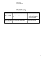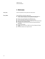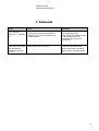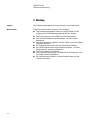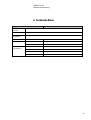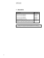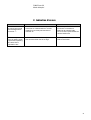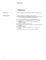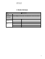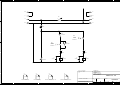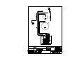
1
PdM-Force-20 Instruction Manual Gebrauchsanweisung Mode d’emploi Manual No.: 15237001 Date of Release .0.20 PdM-Force-20 Instruction Manual Instruction Manual Table of Contents Page User’s Guide ...................................................................................... 1 Reference Guide ................................................................................ 7 Always state Serial No and Voltage/frequency if you have technical questions or when ordering spare parts. You will find the Serial No. and Voltage on the type plate of the machine itself. We may also need the Date and Article No of the manual. This information is found on the front cover. The following restrictions should be observed, as violation of the restrictions may cause cancellation of Struers legal obligations: Instruction Manuals: Struers Instruction Manual may only be used in connection with Struers equipment covered by the Instruction Manual. Service Manuals: Struers Service Manual may only be used by a trained technician authorised by Struers. The Service Manual may only be used in connection with Struers equipment covered by the Service Manual. Struers assumes no responsibility for errors in the manual text/illustrations. The information in this manual is subject to changes without notice. The manual may mention accessories or parts not included in the present version of the equipment. The contents of this manual is the property of Struers. Reproduction of any part of this manual without the written permission of Struers is not allowed. All rights reserved. © Struers 2010. Struers A/S Pederstrupvej 84 DK-2750 Ballerup Denmark Telephone +45 44 600 800 Fax +45 44 600 801 PdM-Force-20 Instruction Manual PdM-Force-20 Safety Precaution Sheet To be read carefully before use 1. The operator(s) should be fully aware of the use of the machine according to the Instruction Manual. 2. The machine must be placed in an adequate working position. 3. If you observe malfunctions or hear unusual noises - stop the machine and call technical service. The equipment should only be used for its intended purpose and as detailed in the Instruction Manual. The equipment is designed for use with consumables supplied by Struers. If subjected to misuse, improper installation, alteration, neglect, accident or improper repair, Struers will accept no responsibility for damage(s) to the user or the equipment. Dismantling of any part of the equipment, during service or repair, should always be performed by a qualified technician (electromechanical, electronic, mechanical, pneumatic, etc.). PdM-Force-20 Instruction Manual Disposal Equipment marked with a WEEE symbol contain electrical and electronic components and must not be disposed of as general waste. Please contact your local authorities for information on the correct method of disposal in accordance with national legislation. PdM-Force-20 Instruction Manual User’s Guide Table of Contents Page 1. Getting Started Checking the Contents ....................................................................... 2 Getting Acquainted with PdM-Force-20 ............................................ 2 PdM-Force-20 mounted on RotoPol-35 (accessory) ................ 2 Setting up PdM-Force-20 ................................................................... 3 Electrical Connection ......................................................................... 3 Mounting the Drip Lubricator (accessory) .......................................... 3 Changing the Lubricator Tube .................................................. 3 2. Operation Mounting the Specimen Mover Plate ................................................. 4 Removing the Specimen Mover Plate ....................................... 4 Inserting a Specimen ......................................................................... 4 Adjusting the Force ............................................................................ 4 Coarse Adjustment ................................................................... 4 Fine Adjustment ........................................................................ 4 Operating PdM-Force-20 ................................................................... 5 Forced Rotation of Specimens ........................................................... 5 Operating the Drip Lubricator ............................................................. 6 Changing Lubricant ................................................................... 6 1 PdM-Force-20 Instruction Manual 1. Getting Started Checking the Contents In the packing box you should find the following parts: 1 PdM-Force-20 1 Allen-key 5 mm for securing PdM-Force-20 on RotoPol-35 1 Nylon tube 4 mm dia., 300 mm long 1 Instruction Manual Getting Acquainted with PdM-Force-20 Take a moment to familiarise yourself with the location and names of the PdM-Force-20 components. PdM-Force-20 mounted on RotoPol-35 (accessory) 2 Thrust pad on adjustment column Release knob Force adjustment column Height adjustment screw Drip lubricator (Accessory) Specimen mover plate PdM-Force-20 Instruction Manual Setting up PdM-Force-20 PdM-Force-20 is designed to be mounted on Struers’ grinding/polishing machine RotoPol-35 only. Please Note For instructions on how to set up and connect RotoPol-35, please see the RotoPol-35 Instruction Manual. Remove the black plastic lid from the pre-punched hole on RotoPol-35. Lead the PdM-Force-20 column through the hole, and position the head of PdM-Force-20 over the turntable of RotoPol-35. Remove the two light grey caps from the left hand side of RotoPol-35. Tighten the two screws with the enclosed allen-key. Move the handle on the left hand side of PdM-Force-20 up, to allow the head to move to the uppermost position. Mount a specimen mover plate on PdM-Force-20. Mount a grinding/polishing disc on RotoPol-35. Press the head down and adjust the distance between preparation disc and specimen mover plate to about 2 mm by turning the black knob on top of PdM-Force-20. Electrical Connection Connect PdM-Force-20 to the female plug on the back of RotoPol35, marked specimen mover. Mounting the Drip Lubricator (accessory) A drip lubricator provides the necessary lubricant during the preparation process. Remove the drip lubricator from its box. Loosen the finger screw underneath PdM-Force-20. Guide the bottom plate of the drip lubricator onto the finger screw and the positioning pin underneath the PdM-Force-20, and retighten the finger screw. Hold the lubricant bottle with one hand and remove the lid. Fill the bottle with lubricant. Replace the lid and the drip lubricator is ready to use. Changing the Lubricator Tube To apply the lubricant to exactly the right spot on the preparation disc, a different length of lubricator tube may be necessary. 300 mm of spare tube is supplied with PdM-Force-20. To remove the present tube from the drip lubricator press back the retaining ring and pull out the tube. To insert the new tube simply press it into the hole in the retaining ring. Use a pair of scissors to cut to the correct length. 3 PdM-Force-20 Instruction Manual 2. Operation Mounting the Specimen Mover Plate Unlock PdM-Force-20 and let it move into top position. Turn PdM-Force-20 to the left over the edge of RotoPol-35. Place the specimen mover plate under the column, align the pin and the slot and press it upwards. Move PdM-Force-20 back into position, press it down and lock the handle. Removing the Specimen Mover Plate As specimens must fit the holes in the specimen mover plate quite accurately, the specimen mover plate must be changed when samples of another size are prepared. To remove a specimen mover plate, turn the plate clockwise to release it. Inserting a Specimen Lift the thrust pad on the adjustment screw to make room for the specimen. Place the specimen in one of the holes of the specimen mover plate and lower the thrust pad. Adjusting the Force Coarse Adjustment There are two ways to adjust the force. Press the release knob and move the column up or down to approximately the correct force. Fine Adjustment Adjust the force by turning the column . The marks on the spring loaded column correspond to the actual force in Newton as stated below: Indication Force 0 0N 1 — 2.5 N 2 – 5N 3 — 7.5 N – 10 N 4 5 — 6 – 7 — 8 – — Thin mark – Black mark 12.5 N 15 N 17.5 N 20 N WARNING Make sure that the pressure feet not in use do not touch the preparation surface. If necessary, press the release button and move the pressure feet not in use upwards. 4 PdM-Force-20 Instruction Manual Operating PdM-Force-20 Press PdM-Force-20 down and turn into the correct position over the preparation disc. Important The specimens should run close to the edge of the preparation disc. The distance should be about 2 mm. Secure PdM-Force-20 in that position by locking the handle Insert the specimens in the specimen mover plate. Important To turn the specimen mover disc use the start and stop keys of PdM-Force-20. Do not turn the specimen mover disc manually. Adjust the force. Adjust the amount of lubricant on the drip lubricator. Press START on RotoPol-35, then press START on PdMForce-20. Perform the preparation step and press STOP on PdM-Force-20, then press STOP on RotoPol-35. Close the valve on the drip lubricator. Forced Rotation of Specimens To avoid directional abrasion of the specimens during preparation PdM-Force-20 is equipped with the ability to carry out forced rotation of the specimens. Simply move the angled stainless steel pin down and press it into the clips on the left hand side of PdM-Force-20. If forced rotation is no longer required move the pin back into the upper position and secure. Steel pin 5 PdM-Force-20 Instruction Manual Operating the Drip Lubricator Changing Lubricant 6 Position the dosing nozzle in the correct position over the preparation disc. Open the valve and adjust the amount of lubricant. After completion of the preparation step close the valve to stop lubricant dosing. Remove the drip lubricator from PdM-Force-20. Hold the lubricant bottle firmly and remove the lid. Pour out the lubricant, and fill the bottle with a mild soap solution. Open the valve to clean the tube. Exchange the soap solution with clean water and repeat the above procedure. Empty the lubricator. Put the lubricator back on PdM-Force-20 and tighten the finger screw. Refill with lubricant and replace the lid. PdM-Force-20 Instruction Manual Reference Guide Table of Contents Page 1. Accessories ............................................................................. 8 2. Trouble-Shooting .................................................................... 9 3. Maintenance Every Day ......................................................................................... 10 Every Week ...................................................................................... 10 4. Technical Data ...................................................................... 11 7 PdM-Force-20 Instruction Manual 1. Accessories Specification Cat. No: Specimen holder plates for 8 x ø 25 mm specimens 05236901 for 8 x ø 30 mm specimens 05236902 for 4 x ø 40 mm specimens 05236903 for 4 x ø 60 mm specimens 05236904 for 8 x specimens 20 x 30 mm 05236905 Drip lubricator Additional drip lubricator for quick changing between different lubricant types 05216908 Remember... Struers offers a comprehensive range of consumables for lapping, grinding and polishing. Please ask for separate leaflets. 8 PdM-Force-20 Instruction Manual 2. Trouble-Shooting Error Cause Action The machine does not operate when the start switch is pressed. - RotoPol-35 is switched off or not connected - Make sure that RotoPol-35 is to the power supply working correctly - PdM-Force-20 is not connected to RotoPol- - Connect the plug from PdM35 Force-20 to the female plug at the back of RotoPol-35 The force adjustment screw is rotating when a specimen is passing the centre of the preparation disc. The friction between the force adjustment screw and the rubber foot is too high Add a drop of oil in the rubber foot to reduce the friction. 9 PdM-Force-20 Instruction Manual 3. Maintenance Every Day Clean the specimen mover plate with a damp cloth. Every Week Clean PdM-Force-20 with a damp cloth. Remove the specimen mover plate and thoroughly clean the column and the coupling on the specimen mover plate. 10 Remove the drip lubricator from PdM-Force-20. Hold the lubricant bottle firmly and remove the lid. Pour out the lubricant, and fill the bottle with a mild soap solution. Open the valve to clean the tube. Exchange the soap solution with water and repeat the above procedure. Empty the lubricator. Put the lubricator back on PdM-Force-20 and tighten the finger screw. Refill with lubricant and replace the lid. PdM-Force-20 Instruction Manual 4. Technical Data Subject Specifications Safety standards Please refer to the Declaration of Conformity Noise level Approx. 45 dB(A) at idle running at a distance of 1.0 m/39.4” from the machine Surrounding temperature 5-40°C / 41-104°F Humidity Non condensing 0-95%RH Supply Power Directly from RotoPol-35 Voltage 24 V Width 140 mm / 5.5” Depth 355 mm / 14.0” Height 315 mm / 12.4” Weight 12 kg / 27 lbs Dimensions and weight 11 PdM-Force-20 Gebrauchsanweisung Gebrauchsanweisung Inhaltsverzeichnis Seite Benutzerhandbuch ............................................................................. 1 Referenzhandbuch ............................................................................. 9 Geben Sie bitte bei technischen Anfragen oder bei der Bestellung von Ersatzteilen immer die Seriennummer und die Spannung/Frequenz an. Diese Angaben finden Sie auf dem am Gerät angebrachten Typenschild. Datum und Artikelnummer der Bedienungsanleitung sind uns u.U. ebenfalls mitzuteilen. Diese Information finden Sie auf dem Deckblatt der Bedienungsanleitung. Beachten Sie bitte die nachstehend genannten Einschränkungen. Zuwiderhandlung kann die Haftung der Firma Struers beschränken oder aufheben: Bedienungsanleitung: Eine von der Firma Struers veröffentlichte Bedienungsanleitung darf nur in Zusammenhang mit den Struers Geräten benutzt werden, für die diese Bedienungsanleitung ausdrücklich bestimmt ist. Wartungshanbuch: Ein von der Firma Struers veröffentlichtes Wartungshandbuch darf nur von ausgebildeten Technikern benutzt werden, die von Struers dazu berechtigt wurden. Das Wartungshandbuch darf nur in Zusammenhang mit dem Struers Gerät benützt werden, für das dieses Wartungshandbuch ausdrücklich bestimmt ist. Struers übernimmt für Irrtümer in Text und Bild der Veröffentlichungen keine Verantwortung. Wir behalten uns das Recht vor, den Inhalt der Bedienungsanleitungen und Wartungshandbücher jederzeit und ohne Vorankündigung zu ändern. In den Bedienungsanleitungen und Wartungshandbüchern können Zubehör und Teile erwähnt sein, die nicht Gegenstand oder Teil der laufenden Geräteversion sind. Inhalt von Bedienungsanleitungen/Wartungshandbücher ist Eigentum der Firma Struers. Kein Teil dieser Veröffentlichungen darf ohne schriftliche Genehmigung von Struers reproduziert werden. Alle Rechte vorbehalten. © Struers 2010. Struers A/S Pederstrupvej 84 DK-2750 Ballerup Dänemark Telefon +45 44 600 800 Fax +45 44 600 801 PdM-Force-20 Gebrauchsanweisung PdM-Force-20 Sicherheitshinweise Vor Gebrauch sorgfältig lesen 1. Der Benutzer sollte sich anhand der Bedienungsanleitung mit dem Gebrauch des Gerätes ausgiebig vertraut machen. 2. Das Gerät muß in einer passenden Arbeitsposition angebracht sein. 3. Das Gerät stoppen; falls es ungewöhnliche Geräusche erzeugt oder falsch funktioniert, und den Kundendienst anrufen. Das Gerät darf nur für seinen vorgesehenen Anwendungszweck und wie in der Gebrauchsanweisung beschrieben verwendet werden. Für die Benutzung der Geräte bzw. der Maschinen sind die Verbrauchsmaterialien von Struers vorgesehen. Falls unzulässiger Gebrauch, falsche Installation, Veränderung, Vernachlässigung, unsachgemäße Reparatur oder ein Unfall vorliegt, übernimmt Struers weder die Verantwortung für Schäden des Benutzers, noch für solche am Gerät. Die für Kundendienst und Reparatur erforderliche Demontage irgendwelcher Teile des Gerätes bzw. der Maschine sollte immer nur von qualifiziertem Fachpersonal (Elektromechanik, Elektronik, Pneumatik usw.) vorgenommen werden. PdM-Force-20 Gebrauchsanweisung Entsorgung Das WEEE-Symbol auf Ihrem Gerät weist darauf hin, dass es sich um ein WEEE-relevantes Gerät handelt, dass entsprechend getrennt entsorgt werden muss. Nähere Informationen über das Recycling dieses Produkts erhalten Sie bei der zuständigen Verwaltungsbehörde. PdM-Force-20 Gebrauchsanweisung Benutzerhandbuch Inhaltsverzeichnis Seite 1. Zu Beginn Packungsinhalt überprüfen ................................................................ 2 PdM-Force-20 kennenlernen ............................................................. 2 PdM-Force-20 auf RotoPol-35 montiert (Zubehör) ................... 2 Aufstellen von PdM-Force-20 ............................................................. 3 Anschluß von PdM-Force-20 ............................................................. 3 Montieren der Tropfvorrichtung (Zubehör) ......................................... 4 Auswechseln des Dosierschlauchs........................................... 4 2. Grundzüge der Bedienung Montierung der Probenbewegerplatte ................................................ 5 Entfernung der Probenbewegerplatte ....................................... 5 Probe einsetzen ................................................................................. 5 Einstellen der Andruckkraft ................................................................ 6 Grobeinstellen ........................................................................... 6 Feineinstellen ............................................................................ 6 Bedienung von PdM-Force-20 ........................................................... 7 Gezwungene Rotation der Proben ..................................................... 7 Bedienung der Tropfvorrichtung ......................................................... 8 Schmiermittel auswechseln ...................................................... 8 1 PdM-Force-20 Gebrauchsanweisung 1. Zu Beginn Packungsinhalt überprüfen Die Verpackung sollte folgende Teile enthalten: 1 PdM-Force-20 1 Inbus-Schlüssel 5 mm zur Sicherung des PdM-Force-20 auf dem RotoPol-35 1 Nylonschlauch 4 mm dia., 300 mm lang 1 Bedienungsanleitung PdM-Force-20 kennenlernen Nehmen Sie sich einen Augenblick Zeit, um die Lage und Bezeichnung aller Teile des PdM-Force-20 kennenzulernen. PdM-Force-20 auf RotoPol-35 montiert (Zubehör) 2 Hebering auf der Einstellsäule Auslöseknopf Krafteinstellssäule Höheneinstellschraube Tropfvorrichtung (Zubehör) Probenbewegerplatte PdM-Force-20 Gebrauchsanweisung Aufstellen von PdM-Force-20 PdM-Force-20 ist nur dafür vorgesehen, auf der Struers Schleif/Poliermaschine RotoPol-35 montiert zu werden. ACHTUNG! Für das Aufstellen und den Anschluß von RotoPol-35, sehen Sie bitte die RotoPol-35 Bedienungsanleitung. Anschluß von PdM-Force-20 Stromanschluß Die schwarze Plastikkappe von der vorgefertigten Montageöffnung auf dem RotoPol-35 entfernen. Die PdM-Force-20 Säule in die Öffnung einführen, und den Kopf des PdM-Force-20 über dem Drehteller des RotoPol-35 anbringen. Die zwei hellgrauen Deckel von der linken Seite des RotoPol-35 entfernen. Die zwei Schrauben mit dem beigelegten Inbus-Schlüssel anziehen. Den Handgriff auf der linken Seite des PdM-Force-20 lösen, so daß der Kopf sich in die oberste Position bewegen kann. Eine Probenbewegerplatte auf dem PdM-Force-20 montieren. Eine Schleif-/Polierscheibe auf dem RotoPol-35 anbringen. Den Kopf nach unten drücken und den Abstand zwischen Präparationsscheibe und Probenbewegerplatte durch Drehen des schwarzen Knopfes oben auf dem PdM-Force-20 auf ca. 2 mm justieren. Den Stecker des PdM-Force-20 in die Steckdose auf der Rückseite des RotoPol-35 stecken. Die Steckdose ist mit einem Schild “Probenhalter” gekennzeichnet. 3 PdM-Force-20 Gebrauchsanweisung Montieren der Tropfvorrichtung (Zubehör) Eine Tropfvorrichtung sorgt während des Präparationsvorgangs für ausreichende Schmierung. Die Tropfvorrichtung aus der Verpackung nehmen. Die Fingerschraube auf der Unterseite des PdM-Force-20 lösen. Die Bodenplatte der Tropfvorrichtung über die Fingerschraube und den Positionsstift unten am PdM-Force-20 führen, und die Fingerschraube anziehen. Die Schmiermittelflasche mit einer Hand festhalten, und den Deckel entfernen Die Flasche mit Schmiermittel auffüllen. Den Deckel wieder auf die Flasche setzen, die Tropfvorrichtung ist jetzt betriebsbereit. Um den Lubrikanten genau an der richtigen Stelle aufbringen zu können, kann es notwendig sein einen Schlauch in anderer Länge anzubringen. Ein zusätzlicher Schlauch, 300 mm lang, ist beigefügt. Auswechseln des Dosierschlauchs 4 Zum Entfernen des Schlauchs den Haltering am Lubrikator eindrücken und den Schlauch herausziehen. Der neue Schlauch wird einfach in die Öffnung des Halteringseingedrückt und anschliessend mit einer Schere auf die richtige Länge abgeschnitten. PdM-Force-20 Gebrauchsanweisung 2. Grundzüge der Bedienung Montierung der Probenbewegerplatte PdM-Force-20 entriegeln und in die höchste Position gleiten lassen. PdM-Force-20 nach links über den Rand der RotoPol Maschine hinausdrehen. Die Probenbewegerplatte unter der Säule anbringen, den Stift und die Ausfräsung ausrichten und die Platte nach oben drücken. PdM-Force-20 in Position zurückbringen, nach unten drücken und den Handgriff verriegeln. Entfernung der Probenbewegerplatte Da die Proben ziemlich genau in die Öffnungen der Probenbewegerplatte passen müssen, ist diese gegen eine geeignete Platte auszuwechseln, wenn Proben anderer Größe zu präparieren sind. Die Probenbewegerplatte durch Drehen im Uhrzeigersinn lösen und entfernen. Probe einsetzen Um Platz für die Probe zu schaffen, die Krafteinstellsäule nach oben bewegen. Die Probe in eine der Öffnungen der Probenbewegerplatte legen, und die Krafteinstellsäule absenken. 5 PdM-Force-20 Gebrauchsanweisung Einstellen der Andruckkraft Es gibt zwei Möglichkeiten, die Kraft einzustellen. Grobeinstellen Der Auslöseknopf drücken und die Säule nach oben oder nach unten bewegen, bis die Kraft ungefähr richtig eingestellt ist. Feineinstellen Die Kraft durch Drehen der Säule einstellen. Die Markierungen auf der durch eine Feder gespannten Säule entsprechen den untenstehenden Kräften in Newton: Anzeige Kraft 0 0N 1 — 2.5 N 2 – 5N 3 — 7.5 N 4 – 10 N 5 — 12.5 N 6 – 15 N 7 — 17.5 N 8 – 20 N — Dünne Markierung Schwarze Markierung – Warnung Es muß darauf geachtet werden, daß die Druckfüße nicht die Präparationsscheibe berühren. Wenn notwending, den Auslöseknopf drücken und die Druckfüße, die nicht in Betrieb sind, nach oben bewegen. 6 PdM-Force-20 Gebrauchsanweisung Bedienung von PdM-Force-20 PdM-Force-20 nach unten drücken, und über der Schleif- oder Polierscheibe in die richtige Arbeitsposition bringen. WICHTIG Die Proben sollten nahe am Rand der Präparationsscheibe laufen. Der Abstand sollte etwa 2 mm betragen PdM-Force-20 in dieser Lage durch Verriegeln des Handgriffs arretieren Die Proben in die Probenbewegerplatte einlegen. WICHTIG Das drehen der Probenbewegerplatte geschieht durch drücken der Start und Stopknöpfe. Die Probenbewegerplatte darf nicht von Hand gedreht werden. Gezwungene Rotation der Proben Die Andruckkraft einstellen. Die Schmiermittelmenge an der Tropfvorrichtung einstellen START am RotoPol-35, und dann START am PdM-Force20 drücken. Nach Beendigung der Stufe STOP am PdM-Force-20 drücken, und dann auf STOP am RotoPol-35 drücken. Schließen Sie das Schraubventil der Tropfvorrichtung Um einen gerichteten Abtrag der Proben während der Präparation zu verhindern, ist PdM-Force-20 mit der Möglichkeit, die Proben während der Präparation gezwungen zu rotieren, ausgestattet. Nehmen Sie einfach den gewinkelten Stift aus rostfreiem Stahl und drücken Sie ihn in die Klemmen an der linken Seite des PdM-Force20 ein. Wenn gezwungene Rotation nicht mehr nötig ist, wird der Stift wieder in die obere Position gebracht und festgemacht. Stift 7 PdM-Force-20 Gebrauchsanweisung Bedienung der Tropfvorrichtung Schmiermittel auswechseln 8 Den Dosierschlauch über der Präparationsscheibe in korrekter Position anbringen. Das Ventil öffnen und die gewünschte Schmiermittelmenge einstellen. Nach Beendigung der Präparationsstufe den Schmiermittelzufluß durch Schließen des Ventils stoppen. Die Tropfvorrichtung vom PdM-Force-20 abschrauben Die Schmiermittelflasche gut festhalten und den Deckel abnehmen. Das Schmiermittel ausgießen, und die Flasche mit einer milden Seifenlösung füllen. Zur Reinigung des Schlauchs das Schraubventil öffnen Das Seifenwasser durch reines Wasser ersetzen, und den beschriebenen Vorgang wiederholen. Die Tropfvorrichtung ausleeren. Die Tropfvorrichtung wieder am PdM-Force-20 anbringen, und die Fingerschraube festziehen. Ein Schmiermittel einfüllen, und den Deckel wieder auf die Flasche schrauben. PdM-Force-20 Gebrauchsanweisung Referenzhandbuch Inhaltsverzeichnis Seite 1. Zubehör ................................................................................... 10 2. Fehlersuche ........................................................................... 11 3. Wartung Täglich .............................................................................................. 12 Wöchentlich ...................................................................................... 12 4. Technische Daten................................................................. 13 9 PdM-Force-20 Gebrauchsanweisung 1. Zubehör Spezifikation Kat. Nr. Probenbewegerplatte für 8 x ø 25 mm Proben 05236901 für 8 x ø 30 mm Proben 05236902 für 4 x ø 40 mm Proben 05236903 für 4 x ø 60 mm Proben 05236904 für 8 x Proben 20 x 30 mm 05236905 Tropfvorrichtung Zusätzliche Tropfvorrichtung zum schnellen Auswechseln unterschiedlicher Schmiermitteltypen. 05216908 Denken Sie daran... Struers führt ein umfangreiches Programm von Verbrauchsmaterialien zum Schleifen/Polieren. Fordern Sie Einzelprospekte und Informationsmaterial an. 10 PdM-Force-20 Gebrauchsanweisung 2. Fehlersuche Fehler Grund Maßnahme Die Maschine läuft - RotoPol-35 ist ausgeschaltet oder nicht an nicht, wenn der die Stromversorgung angeschlossen Startknopf gedrückt - PdM-Force-20 ist nicht an RotoPol-35 angeschlossen ist. - Beachten Sie, daß das RotoPol35 korrekt funktioniert - Den Stecker des PdM-Force-20 in die Steckdose auf der Rückseite des RotoPol-35 einstecken. Die Krafteinstellsäule Die Reibung zwischen der Krafteinstellsäule rotiert wenn eine Probe und dem Gummifuβ ist zu hoch. über die Mitte der Präparationsscheibe kommt. Nehmen Sie den Gummifuβ ab und ölen Sie die Verbindung zwischen Gummifuβ und Säule. Setzen Sie den Gummifuβ wieder auf. 11 PdM-Force-20 Gebrauchsanweisung 3. Wartung Täglich Die Probenbewegerplatte mit einem feuchten Tuch abwischen. Wöchentlich PdM-Force-20 mit einem feuchten Tuch reinigen: Die Probenbewegerplatte entfernen und die Säule und die Kupplung der Probenbewegerplatte gründlich reinigen. 12 Die Tropfvorrichtung vom PdM-Force-20 abschrauben. Die Schmiermittelflasche gut festhalten, und den Deckel abnehmen. Das Schmiermittel ausgießen, und die Flasche mit einer milden Seifenlösung füllen. Zur Reinigung des Schlauchs das Schraubventil öffnen. Das Seifenwasser durch reines Wasser ersetzen , und den beschriebenen Vorgang wiederholen. Die Tropfvorrichtung aus leeren. Die Tropfvorrichtung wieder am PdM-Force-20 anbringen, und die Fingerschraube festziehen. Ein Schmiermittel einfüllen, und den Deckel wieder auf die Flasche schrauben. PdM-Force-20 Gebrauchsanweisung 4. Technische Daten Gegenstand Spezifikationen Sicherheitsnormen Bitte sehen Sie die Konformitätserklärung Geräuschpegel Ca. 45 dB(A) beim Leerlauf bei einem Abstand von 1.0 m/39.4” von der Maschine Umgebungstemperatur 5-40°C / 41-104°F Feuchtigkeit Nicht-kondensierend 0-95%RH Versorgung Stromversorgung Direkt von RotoPol-35 Spannung 24 V Breite 140 mm Tiefe 355 mm Höhe 315 mm Gewicht 12 kg Abmessungen und Gewicht 13 PdM-Force-20 Mode d'emploi Mode d'emploi Table des matières Page Guide de l'utilisateur ........................................................................... 1 Guide de référence ............................................................................ 9 Toujours mentionner le n° de série et la tension/fréquence de l'appareil lors de questions techniques ou de commandes de pièces détachées. Vous trouverez le n° de série et la tension de l'appareil indiqués soit sur la page de garde du mode d'emploi, soit sur une étiquette collée ci-dessous. En cas de doute, veuillez consulter la plaque signalétique de la machine elle-même. La date et le n° de l'article du mode d'emploi peuvent également vous être demandés. Ces renseignements se trouvent sur la page de garde. Les restrictions suivantes doivent être observées. Le non respect de ces restrictions pourra entraîner une annulation des obligations légales de Struers: Mode d'emploi: Le mode d'emploi Struers ne peut être utilisé que pour l'équipement Struers pour lequel il a été spécifiquement rédigé. Manuels de maintenance: Un manuel de service de Struers ne peut être utilisé que par un technicien spécialiste autorisé par Struers. Le manuel de service ne peut être utilisé que pour l'équipement Struers pour lequel il a été spécifiquement rédigé. Struers ne sera pas tenu responsable des conséquences d'éventuelles erreurs pouvant se trouver dans le texte du mode d'emploi/illustrations. Les informations contenues dans ce mode d'emploi pourront subir des modifications ou des changements sans aucun avis préalable. Certains accessoires ou pièces détachées ne faisant pas partie de la présente version de l'équipement peuvent cependant être mentionnés dans le mode d'emploi. Le contenu de ce mode d'emploi est la propriété de Struers. Toute reproduction de ce mode d'emploi, même partielle, nécessite l'autorisation écrite de Struers. Tous droits réservés. © Struers 2010. Struers A/S Pederstrupvej 84 DK-2750 Ballerup Danemark Téléphone +45 44 600 800 Téléfax +45 44 600 801 PdM-Force-20 Mode d'emploi PdM-Force-20 Feuille de sécurité A lire attentivement avant utilisation 1. L'opérateur doit être parfaitement instruit dans l'usage de la machine, selon le Mode d'emploi. La machine doit être correctement montée sur la machine de prépolissage/polissage. 2. S’assurer que la machine est placée dans une position de travail adéquate. 3. En cas de mauvais fonctionnement ou de bruits inhabituels - arrêter la machine et appeler un technicien spécialisé. L’équipement ne devra servir qu’à l’usage auquel il est destiné et ainsi que décrit en détails dans le Mode d’emploi. La machine est conçue pour être utilisée avec des articles consommables fournis par Struers. En cas de mauvais usage, d'installation incorrecte, de modification, de négligence, d'accident ou de réparation impropre, Struers n'acceptera aucune responsabilité pour les dommages causés à l'utilisateur ou à la machine. Le démontage d'une pièce quelconque de la machine, en cas d'entretien ou de réparation, doit toujours être assuré par un technicien qualifié (en électromécanique, électronique, mécanique, pneumatique, etc.). PdM-Force-20 Mode d'emploi Élimination Les équipements marqués d’un symbole WEEE contiennent des composants électriques et électroniques et ne doivent pas être jetés avec les ordures ménagères. Veuillez contacter les autorités locales pour toutes informations sur la procédure correcte d’élimination à suivre selon la législation nationale. PdM-Force-20 Mode d'emploi Guide de l'utilisateur Table des matières Page 1. Installation Vérifier le contenu de l'emballage ...................................................... 2 Se familiariser avec PdM-Force-20 .................................................... 2 PdM-Force-20 enrobé sur RotoPol-35 (accessoire) ................. 2 Installer PdM-Force-20 ....................................................................... 3 Branchement électrique ..................................................................... 3 Monter le lubricateur compte-gouttes (accessoire) ............................ 4 Changer le tube du lubrificateur ................................................ 4 2. Opération Monter la plaque porte-échantillons ................................................... 5 Changer la plaque porte-échantillons ....................................... 5 Insérer un échantillon ......................................................................... 5 Régler la force .................................................................................... 6 Réglage approximatif ................................................................ 6 Réglage fin ................................................................................ 6 Fonctionnement de PdM-Force-20 ................................................... 7 Rotation forcée des échantillons ........................................................ 7 Fonctionnement du lubrificateur compte-gouttes ............................... 8 Changement de lubrifiant .......................................................... 8 1 PdM-Force-20 Mode d'emploi 1. Installation Vérifier le contenu de l'emballage Dans l'emballage se trouvent les pièces suivantes: 1 1 1 1 Se familiariser avec PdM-Force-20 PdM-Force-20 Clé hexagonale de 5 mm pour fixer PdM-Force-20 sur RotoPol-35 Tube en nylon de 4 mm dia. et de 300 mm de longueur. Mode d’emploi Prendre le temps de se familiariser avec l'emplacement et les noms des composants de LaboForce-1. PdM-Force-20 enrobé sur RotoPol-35 (accessoire) 2 Sabot sur la colonne de réglage Bouton de desserrage Colonne de réglage de la force Vis de réglage de la hauteur Lubrificateur compte-gouttes (accessoire) Plaque porte-échantillons PdM-Force-20 Mode d'emploi Installer PdM-Force-20 PdM-Force-20 est conçu pour être monté seulement sur la machine de prépolissage/ polissage de Struers, RotoPol-35. Veuillez noter Pour des instructions concernant l’installation et le branchement de PdM-Force-20 sur RotoPol-35, veuillez consulter le mode d’emploi de RotoPol-35. Branchement électrique Retirer le couvercle noir en plastique de l'orifice prédécoupé sur RotoPol-35. Guider la colonne de PdM-Force-20 à travers l'orifice. Positionner la tête de PdM-Force-20 au dessus de la plaque rotative de RotoPol-35. Retirer les deux bouchons gris du côté gauche de RotoPol-35. Serrer les deux vis avec la clé hexagonale ci-jointe. Lever la poignée sur le côté gauche de PdM-Force-20 pour que la tête puisse arriver en position haute. Monter une plaque porte-échantillons sur PdM-Force-20 Monter un disque de prépolissage/polissage sur RotoPol-35 Presser la tête vers le bas et régler la distance entre le disque de préparation et la plaque porte-échantillons à environ 2 mm en faisant tourner le bouton noir en haut de PdM-Force-20. Brancher PdM-Force-20 à la prise femelle au dos de RotoPol-35, marqué porte-échantillons. 3 PdM-Force-20 Mode d'emploi Monter le lubricateur comptegouttes (accessoire) Un lubrificateur compte gouttes assure l'alimentation nécessaire en lubrifiant pendant le processus de préparation. Changer le tube du lubrificateur 4 Retirer le Lubrificateur compte-gouttes de sa boîte. Desserrer la vis moletée sur le dessous de PdM-Force-20. Guider la plaque inférieure du lubrificateur compte-gouttes sur la vis moletée et la tige de positionnement sous PdM-Force-20, et serrer à nouveau la vis moletée. Tenir d'une main la bouteille de lubrifiant et retirer le couvercle supérieur. Remplir la bouteille de lubrifiant. Placer le couvercle sur la bouteille, et le lubrificateur comptegouttes est prêt à l'emploi. Pour appliquer le lubrifiant à l’endroit exact sur le disque de préparation, il peut s’avérer nécessaire de modifier la longueur du lubrificateur. Un tube de rechange de 300 mm est inclut avec PdMForce-20. Pour retirer le tube présent au lubrificateur compte-gouttes, presser en arrière la bague de retenue, et enlever le tube. Pour insérer le nouveau tube, il suffit de la presser dans l’orifice de la vis moletée. Utiliser une paire de ciseaux pour le raccourcir à la longueur appropriée. PdM-Force-20 Mode d'emploi 2. Opération Monter la plaque porteéchantillons Débloquer PdM-Force-20 et le laisser monter en position supérieure. Faire tourner PdM-Force-20 vers la gauche au dessus du bord de RotoPol-35. Placer la plaque porte-échantillons au dessous de la colonne, aligner la tige et la fente et pousser la plaque porte-échantillons vers le haut. Faire tourner PdM-Force-20 dans sa position initiale, abaisser PdM-Force-20 et bloquer la poignée. Changer la plaque porteéchantillons Comme la taille des échantillons doit correspondre à la taille des orifices de la plaque porte-échantillons, la plaque porteéchantillons doit être changée lorsque des échantillons d'une taille doivent être préparés. Pour changer la plaque porte-échantillons, faire tourner la plaque dans le sens des aiguilles d’une montre pour la débloquer. Insérer un échantillon Soulever le sabot de la colonne de réglage de la force pour donner la place nécessaire à l'échantillon. Placer l'échantillon dans l'un des orifices de la plaque porteéchantillons et abaisser le sabot. 5 PdM-Force-20 Mode d'emploi Régler la force Il y a deux manières de régler la force. Réglage approximatif Presser le bouton de desserrage et faire monter ou descendre la colonne à environ la force correcte. Réglage fin Régler la force en tournant la colonne . Les lignes indiquées sur le barillet de ressort correspondent à la force utilisée indiquée en Newton comme mentionné ci dessous: Indication Force 0 0N 1 — 2.5 N 2 – 5N 3 — 7.5 N 4 – 10 N 5 — 12.5 N 6 – 15 N 7 — 17.5 N 8 – 20 N — ligne fine ligne noir – AVERTISSEMENT S’assurer que les sabots de pression n’étant pas utilisés, ne touchent pas le support de préparation. Si nécessaire, presser le bouton de desserrage, et guider les sabots de pression (non utilisés) vers le haut. 6 PdM-Force-20 Mode d'emploi Fonctionnement de PdM-Force-20 Presser PdM-Force-20 vers le bas et le faire tourner en position correcte au dessus du disque de préparation. Important Les échantillons doivent se déplacer à proximité du bord du disque de préparation. La distance doit être d'environ 2 mm. Fixer PdM-Force-20 dans cette position en bloquant la poignée. Insérer les échantillons dans la plaque porte-échantillons. Important Pour pouvoir tourner la plaque porte-échantillons, utiliser les touches de démarche et d’arrêt sur PdM-Force-20. Ne pas tourner la plaque porteéchantillons manuellement. Rotation forcée des échantillons Régler la force. Régler la quantité de lubrifiant sur le lubrificateur comptegouttes. Appuyer sur MARCHE sur RotoPol-35, et puis appuyer sur MARCHE sur PdM-Force-20. Effectuer l’étape de préparation et appuyer sur STOP sur PdM-Force-20, puis appuyer sur STOP sur RotoPol-35. Fermer la vis du lubrificateur compte-gouttes. Pour éviter l’abrasion directionnelle des échantillons lors de la préparation, il est possible avec PdM-Force-20 de forcer les échantillons à tourner. Il suffit de faire descendre la tige en acier inoxydable et la presser dans les attaches sur le côté gauche de PdM-Force-20. Si la rotation forcée n’est plus nécessaire, il suffit de placer la tige en position supérieure et de la fixer. Tige 7 PdM-Force-20 Mode d'emploi Fonctionnement du lubrificateur compte-gouttes Changement de lubrifiant 8 Positionner le tube de dosage en position correcte sur le disque de préparation. Ouvrir la soupape et régler la quantité de lubrifiant. Une fois l’étape de préparation terminée, refermer la vis pour arrêter le dosage du lubrifiant. Retirer le lubrificateur compte-gouttes de PdM-Force-20. Tenir fermement la bouteille de lubrifiant et ôter le couvercle supérieur. Vider le lubrifiant et remplir la bouteille d'une solution savonneuse légère. Devisser la vis et nettoyer le tube. Remplacer l'eau savonneuse avec de l'eau propre et répéter la procédure ci-dessus. Vider le lubrificateur. Replacer le lubrificateur sur PdM-Force-20 et serrer la vis moletée. Remplir de lubrifiant et monter le couvercle supérieur. PdM-Force-20 Mode d'emploi Guide de référence Table des matières Page 1. Accessoires ........................................................................... 10 2. Indication d’erreurs ............................................................. 11 3. Maintenance Quotidienne ...................................................................................... 12 Hebdomadaire .................................................................................. 12 4. Données techniques ............................................................ 13 9 PdM-Force-20 Mode d'emploi 1. Accessoires Spécification No. de cat. Plaques porte-échantillons pour 8 x ø 25 mm échantillons 05236901 pour 8 x ø 30 mm échantillons 05236902 pour 4 x ø 40 mm échantillons 05236903 pour 4 x ø 60 mm échantillons 05236904 pour 8 x échantillons 20 x 30 mm Lubrificateur compte-gouttes Lubrificateur compte-gouttes supplémentaire pour un changement rapide entre différents types de lubrifiant 05236905 05216908 Se rappeler... Struers offre un large choix de consommables pour le rodage, le prépolissage et le polissage. Veuillez demander les brochures séparées. 10 PdM-Force-20 Mode d'emploi 2. Indication d’erreurs Erreur Cause Action La machine ne fonctionne pas quand la touche de marche est activé . - RotoPol-35 est éteint ou n’est pas branchée sur l’alimentation en courant. - PdM-Force-20 n’est pas branché sur RotoPol-35 - S’assurer que RotoPol-35 fonctionne correctement - Brancher la prise de PdMForce-20 sur la prise femelle au dos de RotoPol-35 The force adjustment screw is rotating when a specimen is passing the centre of the preparation disc. The friction between the force adjustment screw and the rubber foot is too high Add a drop of oil in the rubber foot to reduce the friction. 11 PdM-Force-20 Mode d'emploi 3. Maintenance Quotidienne Nettoyer la plaque porte-échantillons à l'aide d'un chiffon humide. Hebdomadaire Nettoyer PdM-Force-20 à l’aide d’un chiffon humide. Retirer la plaque porte-échantillons et nettoyer à fond la colonne et l’accouplement sur la plaque porte-échantillons. 12 Retirer le lubrificateur compte-gouttes de PdM-Force-20. Tenir fermement la bouteille de lubrifiant et ôter le couvercle supérieur. Vider le lubrifiant et remplir la bouteille d'une solution savonneuse légère. Devisser la vis pour nettoyer le tube. Remplacer l'eau savonneuse par de l'eau et répéter la procédure ci-dessus. Vider le lubrificateur. Remettre le lubrificateur sur LaboForce-1 et serrer la vis moletée. Remplir de lubrifiant et monter le couvercle supérieur. PdM-Force-20 Mode d'emploi 4. Données techniques Sujet Spécifications Standards de sécurité se référer à la Déclaration de conformité Niveau de bruit Environ 45 dB(A) en marche à vide, à une distance de 1.0 m/39.4” de la machine Température environnante 5-40°C / 41-104°F Humidité Pas de condensation 0-95%RH Alimentation en courant Puissance Directement de RotoPol-35 Tension 24 V Largeur 140 mm / 5.5” Profondeur 355 mm / 14.0” Hauteur 315 mm / 12.4” Poids 12 kg / 27 lbs Dimensions et poids 13 PdM-Force-20 Spare Parts and Diagrams Spare Parts and Diagrams Table of contents Drawing Drawings PdM-Force-20, complete ................................................... 15230010C Sample Mover Carrousel, complete ..................................... 15230040 Pressure Foot assembly ...................................................... 15230050 Lubricator, complete ...........................................................15210051E Diagrams Circuit diagrams, PdM-Force-20 .................... 15233100D/15233200A Wiring Diagrams, ................................................................15233450B Some of the drawings may contain position numbers not used in connection with this manual. 1 PdM-Force-20 Spare Parts and Diagrams Drawing Pos. 15230010 2 Spare Part Part No. PdM-Force-20, complete 10 Chassis w. shaft and bearings R5230102 35 Drive pin, 5x30 A4 DIN 7 (5 pcs) RZS11530 40 Ball bearing 6004-2RSR 314MP071 60 Ball bearing 6203-2RSR 2BK00033 80 Locking mechanism, complete 15230055 90 Column 15230130 100 V-ring VS-0040 RIV00040 110 Locking ring, A40 DIN 471 (10 pcs) RZL10400 120 2GF10145 130 Pressure spring, ø16.0 x ø2.0 Lo=145 Guide pin for spring 140 Bridge with screws R5230140 175 Cable W1 190 Elesa button AP B.193/15P-M4X10 2GH00160 230 Gear wheel with key etc. R5230200 260 Gear motor, complete R5230020 300 Capacitor, MK450.30µF450V 359MP075B 350 Sample mover, complete R5230040 380 Front cabinet w. touch pad keyboard 15232902 390 PCB, PdM-Force-20 15233001 420 Adjustment knob 15230060 430 Fixture for stop pin (3 pcs) 15232904 450480 Stop pin for sample rotation 15232903 15270115 PdM-Force-20 Spare Parts and Diagrams Drawing Pos. 15230040 Spare Part Part No. Sample Mover Carrousel, complete 10 Carrousel 15230280 20-30 Locking prawl & spring R5230290 40 Pressure foot, complete 15230050 50 Star Wheel (8 pcs) + Omnifit 50M R5230230 15230050 Pressure Foot, complete 25 O-ring ø5.00-1.00 70 NBR (32 pcs) RIO10006 30 Pressure spring, ø12.5 x ø1 Lo=36.5 (8 pcs) RGF10114 50-60 Lifting disc and locking ring (8 pcs) R5270242 80 Rubber foot (Thrust pad) 249MP015 15210051 Lubricator, complete * O-rings for lubricator 15210055 030 O-ring 6.07-1.78 120 O-ring 2.00-1.00 10 Lubricator bracket 15218503 40 Flow regulator, complete w. tube 15232905 60 Lupo bottle R4820028 70 Lid for Lupo R4820056 140 Tube ø4 mm (5 m) RNU17025 3 12050390- A1 X11A X12A 1 1 M24 1C 9 9 BU 2 2 T1 2C 8 8 BN C1 40µF/450VAC W1 To RotoPol Specimen mover Plug. BK 5 BN 3 3 T2 3M 7 7 RD 4 BU 4 4 N24 2M 6 6 YE 1M 5 5 BK 3 2x1mm² Control Board 2 X12E X11E BK 1 5233200- X1A BK BK YE RD M 2~ PE M1 PE1 BOTTOM ALL WIRINGS 0,75², EXCEPT OTHERWISE MARKED. COLOR CODES: CHASSIS YE/GN BK = BLACK BN = BROWN RD = RED OG = ORANGE GN = GREEN BU = BLUE PE2 PE1 VT = VIOLET GY = GREY WH = WHITE STRUERS A/S PEDERSTRUPVEJ 84 DK-2750 BALLERUP DENMARK Rev.B: FTH 19-11-2009 PHONE: +45 44 600 800 New motor and wire colors + new C1 value Rev.C: AKR 09-03-2010 CIRCUIT DIAGRAM: Wires between A1 and M1 renamed. Rev.D: AKR 20-05-2010 YE and RD wires between A1 and M1 swapped. Rev. A.: Text change ! Side 1 of 2 -> Side 1 of 1. YE = YELLOW FRONT BOTTOM PLATE CHASSIS Size CAGE Code PdM-Force - 20: Thursday, May 20, 2010 Rev DWG NO 15233100 A3 Scale D Sheet 16 Sep. 97 / DEM 1 of 1 5 4 3 2 1 D D M24 2C T1 3M K1B 1 3 T2 2 2M RV1 S10K35 RP 420024 N24 1M V1 1N4007 2 C 1 C K2B RP 420024 3 S2 STOP 4 S1 5 MOTOR OFF K1C RP 420024 START 6 MOTOR ON R2 360R 360R V2 1N4007 K1A RP 420024 B 2200µF/50V V3 1N4007 K2A RP 420024 B C2 + B A R1 A B STRUERS A/S VALHOEJSALLE 176 DK-2610 ROEDOVRE DENMARK PHONE: +45 3670 3500 Rev. A.: Text change ! Side 2 of 2 -> Side 1 of 1. A A1 A2 A3 A4 CIRCUIT DIAGRAM: TEKST TEKST 2050390-.: PCB, 2-Layer. 5020390-.: Drilldrawing. TEKST 5022390/A.: Assembly, Comp. side. 4 PdM-Force - 20: TEKST 5022390/B.: Assembly, Solder side. Size Main File.: 5233100-.DSN 3 CAGE Code DWG NO A3 Wednesday, August 30, 2000 5 A 2 Scale 16 Sep. 97 / DEM Rev 15233200 Sheet 1 1 A of 1 523 PdM-Force-20 31.01.2011 523A_2011 Dansk Overensstemmelseserklæring Fabrikant Struers A/S Pederstrupvej 84 DK-2750 Ballerup, Danmark Telefon 44 600 800 erklærer herved, at Produktnavn: Type nr.: Maskintype: PdM-Force-20 523 Prøvebevæger er i overensstemmelse med følgende EU-direktiver: Maskindirektivet 2006/42/EF efter følgende norm(er): EN ISO 12100-1:2005, EN ISO 12100-2:2005, EN 60204-1:2006/A1:2009. EMC-direktivet 2004/108/EF efter følgende norm(er): EN 61000-6-4:2007EN 61000-6-1:2007, EN 61000-6-3:2007. Lavspændingsdirektivet 2006/95/EF efter følgende norm(er): EN 60204-1:2006/A1:2009. Supplerende oplysninger Endvidere overholdes de amerikanske normer: UL508 Ovenstående overensstemmelse(r) er erklæret iflg. den globale metode, modul A Christian Skjold Heyde, Vice President, Udvikling og Produktion, Struers A/S Dato: 31.01.2011 English Declaration of Conformity Manufacturer Struers A/S Pederstrupvej 84 DK-2750 Ballerup, Denmark Telephone +45 44 600 800 Herewith declares that Product Name: Type No: Machine Type: PdM-Force-20 523 Specimen mover is in conformity with the provisions of the following directives: Safety of Machinery 2006/42/EC according to the following standard(s): EN ISO 12100-1:2005, EN ISO 12100-2:2005, EN 60204-1:2006/A1:2009. EMC-Directive 2004/108/EC according to the following standard(s): EN 61000-6-4:2007EN 61000-6-1:2007, EN 61000-6-3:2007. Low Voltage Directive 2006/95/EC according to the following standard(s): EN 60204-1:2006/A1:2009. Supplementary Information The equipment complies with the American standards: UL508. The above has been declared according to the global method, module A Date: 31.01.2011 Christian Skjold Heyde, Vice President, R& D and Production, Struers A/S Deutsch Konformitätserklärung Hersteller Struers A/S Pederstrupvej 84 DK-2750 Ballerup, Danmark Telefon +45 44 600 800 erklärt hiermit, daß Produktname: Typennr.: Maschinenart: PdM-Force-20 523 Probenbeweger konform ist mit den einschlägigen EG-Richtlinien Sicherheit der Betriebsanlage 2006/42/EG gemäß folgender Normen: EN ISO 12100-1:2005, EN ISO 12100-2:2005, EN 60204-1:2006/A1:2009. EMC-Direktive 2004/108/EG gemäß folgender Normen: EN 61000-6-4:2007EN 61000-6-1:2007, EN 61000-6-3:2007. Niederspannungs Direktive 2006/95/EG gemäß folgender Normen: EN 60204-1:2006/A1:2009. Ergänzungs-information Die Maschine entspricht ebenfalls den amerikanischen FCC Normen: UL508 Die obenstehende Konformität ist in Folge der globalen Methode, Modul A erklärt Christian Skjold Heyde, Stellvertretender Geschäftsführer, Entwicklung und Produktion, Struers A/S Datum: 31.01.2011 Français Déclaration de conformité Fabricant Struers A/S Pederstrupvej 84 DK-2750 Ballerup, Denmark Téléphone +45 44 600 800 Déclare ci-après que Nom du produit: Type no: Type de machine: PdM-Force-20 523 Porte échantillon est conforme aux dispositions des Directives CE suivantes: Sécurité des machines 2006/42/CE conforme aux normes suivantes: EN ISO 12100-1:2005, EN ISO 12100-2:2005, EN 60204-1:2006/A1:2009. Directive EMC 2004/108/CE conforme aux normes suivantes: EN 61000-6-4:2007EN 61000-6-1:2007, EN 61000-6-3:2007. Directive de basse tension 2006/95/CE conforme aux normes suivantes: EN 60204-1:2006/A1:2009. Informations supplémentaires L’équipement est conforme aux standards américains: UL508. La déclaration ci-dessus a été faite d’après la méthode globale, module A Date: 31.01.2011 Christian Skjold Heyde, Vice- President, R& D et Production, Struers A/S