1
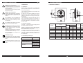
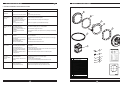
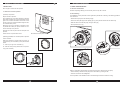
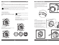
KIT DE NAGE À CONTRE-COURANT
Instructions d’emploi et de maintenance
NAGE BOOSTER
F
0. TABLE DES MATIÈRES.
1. SÉCURITÉ.
1. Sécurité.
1.1. Conseils de base pour la sécurité et la prévention de dommages.
Avertissement pour la sécurité des personnes et des
objets.
2. Généralités.
2.1. Introduction.
2.2. Fonctions principales.
2.3. Caractéristiques techniques.
2.4. Composants principaux.
3. Installation.
3.1. Piscines en structure panneau.
3.2. Piscines en polyester.
3.3. Piscines en maçonnerie.
3.4. Montage de la plaque frontale.
3.5. Montage du tuyau d’air.
3.6. Montage de l’interrupteur de pression.
3.7. Montage de la pompe.
3.8. Mise en marche.
4. Mode d’emploi.
4.1. Marche/Arrêt de la pompe.
4.2. Régulateur d’air.
4.3. Régulateur de débit.
5. Réparation et maintenance.
5.1. Généralités.
5.2. Hivernage.
6. Problèmes possibles, causes et solutions.
7. Dimensions et poids.
8. Déclaration de conformité.
36
Manuel d’instructions
Les symboles suivants
accompagnant
un paragraphe indiquent la possibilité d’un danger si les
recommandations suivantes ne sont pas respectées.
DANGER
La non observation de cette
risque
précaution peut entraîner un risque
d'électrocution d’électrocution.
DANGER
La non observation de cette
précaution peut entraîner un risque
de lésion pour les personnes.
ATTENTION
La non observation de cette
précaution peut endommager
l’appareil ou l’installation.
1.1. Conseils de base pour la sécurité et la prévention de dommages.
ATTENTION lire attentivement les instructions.
Lire attentivement les instructions (14) avant
d’installer ou d’utiliser cet appareil.
MANUEL D’INSTRUCTIONS
F
2. GÉNÉRALITÉS.
DANGER risque d’électrocution.
Prendre toutes les précautions nécessaires
en manipulant l’appareil, car il est branché sur
le secteur et contient de l’eau (très bonne conductrice d’électricité).
Avant toute intervention sur la pompe, il faut la
débrancher du secteur.
INSTRUCTION MANUAL
GB
7. DIMENSIONS AND WEIGHTS.
2.1. Introduction.
L’unité de nage à contre-courant est un appareil pour
piscines permettant d’obtenir un courant d’eau au travers d’une électropompe.
Il est à employer principalement pour la pratique de la
nage à contre-courant.
DANGER câble d’alimentation.
Installer le câble d’alimentation de manière à
éviter de marcher dessus, de le perforer ou de
l’endommager avec un objet situé dans les
environs.
En option, avec un tuyau de massage (non fourni), il
peut diffuser des milliers de petites bulles procurant à
l’utilisateur les bienfaits d’un massage aux effets hydrothérapeutiques.
Il est disponible avec une plaque au design rond ou
carré et peut également disposer d’un accessoire de
coffret mural de commande de la pompe en trois versions selon l’alimentation ou la puissance de l’électropompe à installer.
Pour l’installation, suivre les indications de
sécurité pour piscines et les indications particulières de la pompe à installer (non fournie
avec l’appareil).
Pour l’installation de l’appareil, il faut respecter les normes de sécurité en vigueur.
2.2. Fonctions principales.
INTERDICTION de manipuler ou de réparer.
Les manipulations ou les réparations ne doivent être effectuées que par des services
techniques officiels.
L’utilisateur ne devra faire que les manipulations indiquées dans le manuel.
Le fabricant décline toute responsabilité en
cas de manipulations non indiquées effectuées par l’utilisateur.
MODEL
b) Blower : il comprend le contrôle de bulles par l’étranglement du passage de l’air qui, par un effet venturi, est
diffusé simultanément avec le jet d’eau.
KIT NCR
X
KIT NCRM
X
KIT NCRT1
X
KIT NCRT2
X
c) Interrupteur de Marche/Arrêt Pompe : pour la sécurité électrique, il dispose d’un bouton pneumatique qui
commande à distance l’interrupteur pneumatique du
coffret de commande. Pour mettre en marche ou arrêter l’électropompe.
ATTENTION nettoyage.
Toujours nettoyer avec un chiffon humide et
une solution de savon neutre. Ne pas utiliser
de produits contenant des dissolvants ou des
acides.
2.3. Caractéristiques techniques.
Débit maximum admissible
80 m3/h
Débit minimum recommandé
40 m3/h
Connexions hydrauliques
Ne pas laisser fonctionner la pompe à vide,
l’eau de la piscine doit recouvrir toute la
façade.
Connexions électriques
CONTROL CABINET
PLATE
a) Hydrojet : il comprend la fonction de réglage manuel
du débit et l’orientation du jet d’eau.
ROUND
1~ 230V
<2,2kW
SQUARE
X
X
KIT NCC
X
KIT NCCM
X
KIT NCCT1
X
KIT NCCT2
X
X
X
X
Ø 63 intérieur
NC_M 1 ~ 230 V
NC_M 16A
NC_T1 6.3A
NC_T2 10A
2
35
A
WEIGHT
(Kg)
314
4
314
4.7
314
4.7
314
4.7
3kW
X
NC_T_ 3 ~ 400 V
Intensité maximale
admissible
3~ 400V
340
4
340
4.7
340
4.7
340
4.7
INSTRUCTION MANUAL
GB
MANUEL D’INSTRUCTIONS
F
6. POSSIBLE PROBLEMS, CAUSES AND SOLUTIONS.
2.4. Composants principaux.
PROBLEMS
– Water flow is
insufficient
SOLUTIONS
CAUSES
– Recirculation of water.
– Maximum flow of the pump is small.
1
– Check correct fitting of components, and particularly that the gasket has been
fitted.
– Check correct pump dimensioning.
2 x3
– No air bubbles
emerge
– The pump does not
start
– The filter (9) fitted in the hose is
dirty and air does not pass.
– Air passage at the front plate (6) is
obstructed by insects or foreign
bodies.
– The air regulator is closed.
– Clean the filter (9) and remove impurities.
– The capillary pipe (7) is
disconnected or has leaks.
– There is no electricity supply to the
installation.
– Incorrect pressure microswitch
operation.
– Check that the capillary pipe (7) is correctly installed.
– The pump thermal cut-out switch
activates.
– The motor-protection cut-out on the
panel throws.
– The installation’s differential circuitbreaker switch triggers
– Electrical connection failure.
– Check that the premises is correctly ventilated and that air passage of the pump
fan is not obstructed.
– Check that the pump ampere rating is less than or equal to the cut-out trigger
rating.
– Check for insulation or shunt-off faults.
– The pump is not primed.
– The suction pipes are not sealed
and the pump takes in air.
– The suction piping is long and the
pump is higher than the swimming
pool level.
– Pool water level insufficient and air
is being taken in.
– Fill the suction body up to the level of the suction connection.
– Repair leaks.
– Bleed air from the pump.
– A check valve without spring pressure must be mounted in the suction pipes to
prevent water draining during suction.
– Condenser defective.
– Check that the condenser is of the correct capacity.
– Replace if faulty.
– The motor shaft must rotate slightly.
– If not, the pump must be repaired by the technical service centre.
– Clean and ensure that air is passing to the discharge pipe.
3
– When the air regulator is opened bubbles should emerge.
4
5
– Wait for electricity supply to be restored.
– Check electrical continuity at the pressure switch by activating and deactivating
the button.
7
– The pump stops
running
– The pump does not
take in water
– The motor
protection switch
triggers
– Noise.
– Pump blocked by obstruction of the
turbine.
– Air is entering the equipment.
– Noise from bearings.
– Foreign bodies in the pump.
6
– Check that electrical connections are correct.
8
*
9 x2
– Raise the water level of the pool to at least 10 cm above the plate.
14
10 x2
– Stop leaks.
– The pump must be repaired by the technical service centre.
– Remove them as explained in the pump maintenance manual.
34
11 x12
1
2
3
4
5
6
7
8
9
10
11
12
13
14
15
PIÈCE/MODÈLE
Contrebride fixation
Joint mousse
Corps arrière
Plaque de protection
Bride fixation
Facade
Tube capillaire
Coffret électrique (optionnel)*
Filtre mousse
Clip fixation
Vis DIN7982 Ø 4,8 x 45
Vis DIN965 M 5 x 30
Vis DIN DIN7982 Ø 5,5 x 16
Manuel d’instructions
Gabarit
12 x3
13 x2
15
3
MANUEL D’INSTRUCTIONS
F
INSTRUCTION MANUAL
3. INSTALLATION.
5. REPAIR AND MAINTENANCE.
Selon le type de construction de la piscine.
5.1. General considerations.
GB
Check the air-passage filter (9) and if necessary clean out any dirt or insects.
3.1. Piscines en structure panneau.
5.2. Overwintering.
a) Découpe du panneau.
Séparer la toile du panneau.
The installation must be protected in winter against the potential risk of freezing. The following operations will have
to be carried out:
A
Poser le gabarit (15) sur la partie intérieure du panneau
de la piscine en faisant en sorte que la distance entre la
ligne XY et la hauteur maximale de la structure soit de
400 mm. La ligne XY doit être parallèle à la ligne de hauteur maximale de la piscine.
– Disconnect the pump from the electricity supply.
X
Y
B
– Remove the front plate (6) and the capillary pipe (7) of the pressure switch and stow them away.
– Drain the water from inside the pump, using the drain plug.
– Fit the protective cover (4).
Marquer les 14 trous de montage et découper la zone
en pointillés du modèle pour pouvoir dessiner les contours de découpe sur le panneau.
Découper au contour et percer les trous marqués sur le
panneau.
Partie intérieure de la piscine
Prendre soin de ne pas déchirer la toile.
b) Montage préalable, avec la toile séparée du panneau
et selon le dessin.
A
Nettoyer les surfaces de contact entre les joints (2), le
corps arrière (3) et la contrebride (1) et le panneau de la
piscine.
A. – Coller un joint (2) sur la contrebride (1).
B. – Coller les deux joints (2) restants sur le corps arrière (3) (selon le dessin).
B
After the overwintering period refit the components removed and, before running the pump:
– Check manually to ensure that the pump motor shaft rotates, by rotating the fan.
– Check the connections for leaktightness.
Correct operation of the installation must be checked during the first few minutes of running.
4
33
INSTRUCTION MANUAL
GB
3.8. Start-up.
Once the connections have been made and before running the pump the leaktightness of joints must be checked.
Switch on the water supply to the pump and eliminate any air left inside the pump by using the bleed devices on the
pump.
Start up the pump. Press “Start” on the electrical panel (8) and press the pneumatic pump-start button.
The pipe valves must be fully open during pump operation and must never be closed while it is running.
Shutting off or quickly reducing the passage of water can give rise to pressure surges that could lead to
equipment breakage.
MANUEL D’INSTRUCTIONS
F
C. – Fixer la contrebride (1) sur la partie arrière du panneau de la piscine, poser le corps arrière (3) de l’autre
côté du panneau et le fixer fermement à sa place tout en
vissant les 2 vis (13) dans les trous A et B.
C
D. S’assurer que le corps arrière (3) est en position
correcte. Le mot “HAUT” doit se trouver sur la partie
supérieure.
A
Leave the pump running for a few minutes and check that the equipment has been correctly installed.
D
B
4. INSTRUCTIONS FOR USE.
4.1. Starting / Stopping the pump.
Keep air passage closed if the massage hose
is not in use.
The pump will come into operation when the pneumatic
pushbutton is pressed, and will stop if it is pressed
again.
Note: The hydromassage hose is an accessory not supplied with the equipment.
4.3. Flow regulator.
The water flow can be adjusted by turning the discharge
pipe to the right or to the left.
The direction of the water jet can also be adjusted using
the discharge pipe knuckle-joint system.
A
c) Montage.
Après avoir posé le liner, remplir la piscine d’eau,
environ 15 cm, pour bien le tendre.
A. – Poser la bride (5) sur la toile, en cherchant
la position et en profitant du saillant de la plaque
de protection (4) pour la positionner. Introduire
les vis (11) en perçant la toile et visser à fond. Il
faut éviter de trop serrer les vis.
B. – Après avoir fixé toutes les vis, découper la
partie intérieure du liner avec un cutter.
4.2. Air regulator.
C. – Retirer la plaque de protection (4) et la ranger.
With the hydromassage hose connected, turn the regulating button to regulate the air bubbles.
B
Maximum
32
Medium
FLOW
C
Minimum
5
MANUEL D’INSTRUCTIONS
INSTRUCTION MANUAL
F
3.2. Piscines en polyester.
GB
c) Electrical wiring.
a) Découpe du panneau.
Installation and assembly must be entrusted
to an authorised installer.
The wiring must be in accordance with EEC
standard or of type H07 RN-F according to
VDE 0250.
Poser le gabarit (15) sur la partie intérieure du panneau
de la piscine, de manière à ce que la distance entre la
ligne XY et la hauteur maximale de la structure soit de
400 mm. La ligne XY doit être parallèle à la ligne de hauteur maximale de la piscine.
The electrical trunking must be watertight, and
connections and their fittings must have a sufficient degree of protection against vertical fall
of water drops. Connections, trunks and
branch connections must always be housed in
leaktight boxes.
A
X
Marquer les 14 trous de montage et découper la zone
en pointillés du modèle, pour pouvoir dessiner les contours de découpe sur le panneau.
Y
B
Découper au contour et percer les trous marqués sur le
panneau.
Wiring diagram
Partie intérieure de la piscine
b) Montage préalable, selon le dessin :
Nettoyer les surfaces de contact entre les joints
(2), le corps arrière (3) et la contrebride (1) et le
panneau de la piscine.
A
B
A. – Coller un joint (2) sur la contrebride (1).
B. – Coller un joint (2) sur le corps arrière (3).
Single-phase control cabinet
Three-phase control cabinet
C
C. – Fixer la contrebride (1) sur la partie arrière du panneau de la piscine, poser le corps arrière (3) de l’autre
côté du panneau et le fixer fermement à sa place tout en
vissant les 2 vis (13) dans les trous A et B.
A
B
6
31
INSTRUCTION MANUAL
GB
3.7. Fitting the pump.
MANUEL D’INSTRUCTIONS
F
D. - S’assurer que le corps arrière (3) est en position
correcte. Le mot “HAUT” doit se trouver sur la partie
supérieure.
Pump installation and assembly must be carried out by
an authorised installer.
D
a) General safety warnings.
Particular care must be paid to ensure that
water cannot enter the pump motor or other
electrically powered parts of the installation.
The equipment must be fitted following current
safety regulations for installing swimming
pools, and particularly standard IEC 60364-7702 and the special regulations for each application.
The premises in which the pump is installed
must comply with the complementary technical safety instructions applicable to damp or
wet premises.
The pump must be installed on a flat surface
and attached to the floor.
To ensure the safety of persons, the pump
must be installed at least 3.5 metres from the
swimming pool.
The premises must be provided with a drain
that allows water to be evacuated in the event
of flooding of the premises that might be detrimental to electrical safety and cause injury to
persons.
The mains electricity supply must be protected by an automatic power-supply cut-out
device, a residual current circuit-breaker
switch (∆fn) not exceeding 30 mA.
For optimum pump operation and reliability
the premises must be provided with a ventilation inlet.
c) Montage.
A. – Coller le joint (2) sur la bride (5).
B. – Poser la bride (5) sur le corps arrière (3). Introduire les vis (11) jusqu’au fond. Il faut éviter de trop serrer les vis.
C. – Retirer la plaque de protection (4) et la ranger.
A
b) Fitting the pipes.
The connection pipes to the pump for distances of up to 3.5 metres must have a minimum
diameter of DN63. For distances of up to 5
metres from the swimming pool piping of
DN75 must be used, and DN90 piping for distances of more than 5 metres.
The installation pipes and accessories must
be made of PVC. Under no circumstances
must iron pipes or accessories be used, as
they could damage the plastic components of
the installation.
B
Flow valves must be fitted in the discharge
and suction pipes, so that the pump can be
removed for maintenance without draining the
swimming pool.
Flow valves
C
30
7
MANUEL D’INSTRUCTIONS
F
INSTRUCTION MANUAL
GB
3.3. Piscines en maçonnerie.
3.5. Fitting the air hose
Poser le gabarit (15) sur la partie intérieure du coffrage de la piscine de manière à ce que la distance entre la ligne XY et la hauteur maximale de la
structure soit de 400 mm. La ligne XY doit être
parallèle à la ligne de hauteur maximale de la piscine.
A. The hose must be attached to the wall to form an air trap, or at a level above the maximum height of the swimming
pool, so as to avoid emptying the pool. Alternatively, it can be attached to the wall at a height between the waterline
and the maximum height of the pool. Use a securing staple (10) to ensure correct fitting.
A
B. Mount the filter (9) on the end of the hose in order to prevent dirt entering.
X
A
Y
Marquer et percer sur le panneau du coffrage les
trous A et B.
B
Partie intérieure de la piscine
B
b) Montage.
A. – Nettoyer le côté à adhérer de la contrebride (1) et ensuite fixer le joint (2).
B. – Monter le corps arrière (3) sur la contrebride (1) et fixer l’ensemble à la structure du coffrage avec deux vis
(DIN7982. Ø 5,5) dans les positions A et B, ces vis devant être fournies par l’installateur en fonction de l’épaisseur
du panneau de coffrage.
C. – S’assurer que le corps arrière (3) est en position correcte. Le mot « HAUT » doit se trouver sur la partie supérieure.
3.6. Fitting the pressure switch.
A. The hose must be attached to the wall to form an air trap, or at a level above the maximum height of the swimming
pool, so as to avoid emptying the pool. Use a securing staple (10) to ensure correct fitting.
A
B
B. Cut the hose to the right length to reach the panel (8) and mount the filter (9) on the end of the hose in order to
prevent dirt entering.
The maximum length to ensure correct operation of the pressure switch is 25 metres. It is advisable to cut the capillary pipe to just the right length to reach the panel (8), ensuring that the connecting pipe is passed through again.
C. Connect the capillary pipe (7) to the pressure switch, ensuring that it is firmly connected.
A
A
B
C
B
C
8
29
INSTRUCTION MANUAL
GB
3.4. Fitting front plate.
Pass the capillary pipe (7) through the hole in the rear body (3) until it emerges from the end of the hose on the side
of the connections to the pump.
Fit the capillary pipe (7) by pressing it into the pressure switch and ensuring that it is securely connected. Offer the
front plate (6) up to the rear body (3), ensuring that the rubber gasket is in place before fixing the unit with the 3 M5
screws (12).
MANUEL D’INSTRUCTIONS
F
Il faut faire en sorte d’éviter le passage de ciment entre le panneau du coffrage et le corps arrière (3) ; si besoin est,
mettre entre les deux une plaque de polystyrène pour boucher les rainures éventuelles.
Si la largeur du coffrage est plus grande que la largeur des manchons de branchement, fixer et coller les tuyaux d’entrée et de sortie d’eau correspondants.
Les tuyaux de sortie pour la commande de l’interrupteur pneumatique et de l’entrée d’air doivent traverser le panneau de coffrage. Ces tuyaux sont pourvus d’une gaine ondulée pour éviter l’adhérence du ciment sur les tuyaux.
Vue supérieure:
A
Tuyaux d’entrée
et de sortie d’eau
D. – Coller le joint (2) sur la bride (5).
B
E. – Après avoir retiré le coffrage, poser la bride (5) sur le corps arrière (3) face aux 12 trous. Introduire les vis (11).
Il faut éviter de trop serrer les vis.
F. – Retirer la plaque de protection (4) et la ranger.
D
Rubber gasket
E
F
28
9
MANUEL D’INSTRUCTIONS
INSTRUCTION MANUAL
F
3.4. Montage plaque frontale.
GB
Care must be taken to ensure that no cement passes between the formwork board and the rear body (3), if necessary placing a sheet of polystyrene between them to cover up any grooves.
Faire passer le tube capillaire (7) dans le trou du corps arrière (3) jusqu’à ce qu’il sorte au bout du tuyau du côté des
connexions à la pompe.
Monter à pression le tube capillaire (7) sur l’interrupteur de pression assurant la connexion et poser la plaque frontale (6) sur le corps arrière (3) en prenant soin d’éviter d’endommager le joint en caoutchouc avant de fixer l’ensemble avec les 3 vis M5 (12).
If the width of the formwork exceeds the width of the connecting hoses, attach and glue in place the corresponding
water inlet and outlet pipes.
The outlet pipes for pneumatic switch and air inlet control must pass through the formwork board. These pipes are
housed inside a corrugated casing to prevent cement adhering to the pipes.
Upper view:
A
Water inlet
and outlet pipes
D. Attach the gasket (2) to the flange (5).
B
E. Once the formwork has been removed, locate the flange (5) on the rear body (3) in alignment with the 12 holes.
Insert the screws (11). Avoid the use of excessive force when driving home the screws.
F. Withdraw the protective plate (4) and keep it safely.
D
Joint en caoutchouc
E
F
10
27
INSTRUCTION MANUAL
GB
MANUEL D’INSTRUCTIONS
F
3.3. Masonry swimming pools.
3.5. Montage du tuyau d’air.
a) Preparatory work.
A. – Le tuyau doit être fixé au mur en faisant siphon ou être fixé à la sortie sur un niveau supérieur à la hauteur maximale de la piscine de manière à éviter le vidage de la piscine. Ou bien, le tuyau doit être fixé au mur entre le niveau
de l’eau et la hauteur maximale de la piscine. Utiliser un clip (10) de fixation pour assurer le montage.
Place the template (15) on the interior part of the swimming pool formwork, such that the distance between the
plane XY and the maximum height of the structure is
400 mm. The plane XY must be parallel to the maximum-height plane of the swimming pool.
A
B. – Au bout du tuyau, monter le filtre (9) pour éviter l’entrée de saletés.
A
X
Y
Mark out and drill holes A and B in the formwork board.
B
Interior part of the swimming pool
B
b) Assembly.
A. Clean the gluing side of the counterflange (1), then attach the gasket (2).
B. Mount the rear body (3) on the counterflange (1) and attach the assembly onto the formwork structure using two
screws (DIN 7982, Ø 5.5) in positions A and B, to be provided by the installer and depending on the thickness of the
formwork board.
C. Ensure that the rear body (3) is in the correct position. The work “HAUT” must be at the top part.
3.6. Montage de l’interrupteur de pression.
A. – Le tuyau doit être fixé au mur en faisant siphon ou être fixé à la sortie sur un niveau supérieur à la hauteur maximale de la piscine de manière à éviter le vidage de la piscine. Utiliser un clip (10) de fixation pour assurer le montage.
A
B
B. – Couper le tuyau à la dimension exacte pour arriver jusqu’au coffret (8) et monter le filtre (9) au bout du tuyau
pour éviter l’entrée de saletés.
La longueur maximale pour assurer le fonctionnement correct de l’interrupteur de pression est de 25 mètres. Il est
conseillé de couper le tube capillaire à la dimension exacte pour arriver jusqu’au coffret (8). Ne pas oublier de réinstaller le tuyau de connexion.
C. – Brancher le tube capillaire (7) sur l’interrupteur de pression assurant la connexion.
A
A
B
C
B
C
26
11
MANUEL D’INSTRUCTIONS
INSTRUCTION MANUAL
F
3.7. Montage de la pompe
GB
D. Ensure that the rear body (3) is in correct position.
The word “HAUT” must be at the top part.
D
L’installation et le montage de la pompe doivent être réalisés par un installateur agréé.
a) Prescriptions générales de sécurité.
Il faut faire en sorte d’éviter qu’il puisse entrer
de l’eau dans le moteur de la pompe ou dans
d’autres parties électriques sous tension de
l’installation.
L’appareil doit être monté aux normes de
sécurité en vigueur pour l’installation de piscines et en particulier à la norme IEC 60364-7702 et aux normes particulières à chaque
application.
Le local où est installée la pompe doit respecter les instructions techniques complémentaires de sécurité applicables pour les conditions
de locaux humides ou mouillés.
La pompe doit être installée sur un endroit plat
en la fixant sur le sol.
c) Assembly.
Pour la sécurité des personnes, il faut installer
la pompe à une distance d’au moins 3,5 m de
la piscine.
Le local doit être pourvu d’un écoulement
d’eau permettant l’évacuation d’eau en cas
d’inondation, pour une meilleure sécurité électrique et pour éviter tout risque de lésion sur
les personnes.
En cas d’installation dans un regard contigu
au bassin, se référer à la norme française en
viguer.
Le local doit être pourvu d’une entrée de ventilation pour un excellent fonctionnement et
une bonne fiabilité de la pompe.
Le secteur d’alimentation électrique doit être
protégé par un dispositif de coupure automatique de l’alimentation, un disjoncteur différentiel à courant résiduel (∆fn) ne dépassant pas
30 mA.
A. Stick the gasket (2) to the flange (5).
B. Place the flange (5) on the rear body (3). Drive the screws (11) fully home. Avoid excessive force when driving
home the screws.
C. Withdraw the protective plate (4) and stow it safely.
A
b) Montage des tuyauteries.
Les tuyauteries de connexion à la pompe pour
des distances de jusqu’à 3,5 m doivent avoir
un diamètre minimum de DN63. Pour des distances de jusqu’à 5 m de la piscine, il faut utiliser une tuyauterie de DN75 ; à partir de 5 m,
utiliser une tuyauterie de DN90.
Les tuyauteries et les accessoires de l’installation doivent être en PVC, il ne faut en
aucun cas utiliser d’accessoires ou de tuyauteries en fer car ils pourraient endommager
les composants plastiques de l’installation.
B
Il faut monter deux vannes d’isolement sur les
tuyauteries de refoulement et d’aspiration, afin
de permettre le démontage de la pompe pour
sa maintenance sans avoir à vider la piscine.
C
Vannes d'isolement
12
25
INSTRUCTION MANUAL
GB
3.2. Polyester swimming pools.
MANUEL D’INSTRUCTIONS
F
c) Branchement électrique.
a) Cutting the panel.
Le câblage doit correspondre à la norme CEE
ou bien au type H07 RN-F selon VDE 0250.
Place the template (15) on the interior part of the swimming pool panel, such that the distance between the
plane XY and the maximum height of the structure is
400 mm. The plane XY must be parallel to the maximum-height plane of the swimming pool.
L’installation et le montage doivent être effectués par un installateur agréé.
A
Les canalisations électriques doivent être
étanches, les connexions et leurs appareillages doivent présenter le degré de protection
correspondant à la chute verticale de gouttes
d’eau. Les connexions, les raccordements et
les dérivations doivent toujours être réalisés à
l’intérieur de coffrets étanches.
X
Y
Mark the 14 assembly holes and cut along the dottedline zone of the template so as to mark the cut outline on
the panel.
B
Cut the outline and drill the holes marked in the panel.
Schéma de branchements
Interior part of the swimming pool
b) Pre-assembly, according to the drawing:
Clean the contact surfaces between the gaskets
(2), rear body (3) and counterflange (1) and the
panel of the swimming pool.
A
B
A. Stick a gasket (2) onto the counterflange (1).
B. Stick a gasket (2) onto the rear body (3).
C. Secure the counterflange (1) through the rear part of
the swimming pool panel, fit the rear body (3) from the
other side of the panel and hold it firmly in place while
the two screws (13) are driven into the holes A and B.
C
Coffret commande monophasée
Coffret commande triphasée
A
B
24
13
MANUEL D’INSTRUCTIONS
F
3.8. Mise en marche.
Après avoir réalisé les branchements et avant de mettre en marche la pompe, il faut vérifier l’étanchéité des unions.
Ouvrir le passage d’eau à la pompe et éliminer les restes d’air à l’intérieur de la pompe à l’aide des purgeurs disponibles sur la pompe.
Mettre la pompe en marche : appuyer sur « Start » sur le coffret électrique (8) et actionner le bouton pneumatique
de marche de la pompe.
INSTRUCTION MANUAL
GB
C. Secure the counterflange (1) through the rear part of
the swimming pool panel, fit the rear body (3) from the
other side of the panel and hold it firmly in place while
the two screws (13) are driven into the holes A and B.
C
D. Ensure that the rear body (3) is in correct position.
The word “HAUT” must be at the top part.
A
Durant le fonctionnement de la pompe, les vannes de la tuyauterie doivent être complètement ouverts. Il ne
faut jamais fermer les vannes durant le fonctionnement de la pompe : la fermeture ou la réduction rapide du
passage de l’eau peut provoquer des coups de pression capables d’entraîner la rupture des appareils.
D
Maintenir la pompe en marche quelques minutes et vérifier l’installation correcte de l’appareil.
B
4. MODE D’EMPLOI.
4.1. Marche/Arrêt de la pompe.
Fermer le passage d’air quand on n’utilise pas
le tuyau de massage.
En appuyant sur le bouton pneumatique, la pompe se
met en marche. Si on appuie de nouveau sur le bouton,
la pompe s’arrête.
Remarque : le tuyau d’hydromassage est un accessoire
non fourni avec l’appareil.
4.3. Régulateur de débit.
c) Assembly.
On peut régler le débit d’eau en tournant à droite ou à
gauche la base de l’hydrojet.
After fitting the canvas, fill the swimming pool
with approximately 15 cm of water so that it is
well tensioned.
On peut également diriger le jet d’eau grâce au système
de rotule de la base.
A
A. Place the flange (5) on the canvas, seeking
out the right position and making use of the lip
of the protective plate (4) to position it. Insert
the screws (11) so that they pierce the canvas
and then drive them fully home. Avoid excessive force when driving home the screws.
B. Once all the screws are secured, cut the
interior part of the canvas with a cutter.
C. Remove the protective plate (4) and stow it
safely.
4.2. Régulateur d’air.
Quand le tuyau d’hydromassage est connecté, tourner
le bouton régulateur pour régler les bulles d’air.
B
Maximum
14
Moyen
DÉBIT
C
Minimum
23
INSTRUCTION MANUAL
GB
3. INSTALLATION.
MANUEL D’INSTRUCTIONS
F
5. RÉPARATION ET MAINTENANCE.
According to swimming pool construction type.
5.1. Généralités.
Vérifier et, si nécessaire, nettoyer les saletés ou les insectes se trouvant dans le filtre (9) de passage d’air.
3.1. Panel-structure swimming pools.
a) Cutting the panel.
A
Remove the canvas from the panel.
5.2. Hivernage.
L’installation doit être protégée en hiver contre tout risque de gelées. Il faut réaliser les opérations suivantes :
X
Place the template (15) on the interior part of the swimming pool panel, such that the distance between the
plane XY and the maximum height of the structure is
400 mm. The plane XY must be parallel to the maximum-height plane of the swimming pool.
Y
B
– Débrancher la pompe de l’alimentation électrique.
– Démonter la plaque frontale (6) et le tube capillaire (7) de l’interrupteur de pression et les ranger.
– Vider l’eau de l’intérieur de la pompe à l’aide du bouchon de purge.
– Poser le couvercle de protection (4).
Mark the 14 assembly holes and cut along the dottedline zone of the template so as to mark the cut outline on
the panel.
Cut the outline and drill the holes marked on the panel.
Take care not to damage the canvas.
Interior part of the swimming pool
b) Pre-assembly, with the canvas removed from the
panel and according to the drawing:
A
Clean the contact surfaces between the gaskets (2),
rear body (3) and counterflange (1) and the panel of the
swimming pool.
A. Stick a gasket (2) onto the counterflange (1).
B. Stick the remaining two gaskets (2) onto the rear body
(3) (according to drawing).
B
Après la période d’hivernage, remonter les composants démontés et avant de mettre en marche la pompe :
– Vérifier à la main si l’arbre moteur de la pompe tourne, en faisant tourner le ventilateur.
– Vérifier l’étanchéité des connexions.
Durant les premières minutes de fonctionnement, il faut contrôler le fonctionnement correct de l’installation.
22
15
MANUEL D’INSTRUCTIONS
INSTRUCTION MANUAL
F
GB
6. PROBLÈMES POSSIBLES, CAUSES ET SOLUTIONS.
2.4. Main components.
PROBLÈMES
SOLUTIONS
CAUSES
– Le débit d’eau est
insuffisant.
– Recirculation d’eau.
– Le débit maximum de la pompe est
faible.
– Vérifier le montage correct des composants et en particulier la présence du joint.
– Vérifier le dimensionnement correct de la pompe.
– Les bulles d’air ne
sortent pas.
– Le filtre (9) monté sur le tuyau est
sale et l’air ne passe pas.
– Le passage de l’air dans la plaque
frontale (6) est bouché par des
insectes ou des objets étrangers.
– Le régulateur d’air est fermé.
– Nettoyer le filtre (9) et éliminer les saletés.
– Le tube capillaire (7) est débranché
ou a des fuites.
– Il y a une coupure de courant dans
l’installation.
– Fonctionnement de l’interrupteur de
pression incorrect.
– Vérifier l’installation correcte du tube capillaire (7).
1
2 x3
– La pompe ne
démarre pas.
– Nettoyer et assurer le passage de l’air vers le blower.
3
– En ouvrant le régulateur d’air, les bulles devraient sortir.
4
5
– Attendre le retour du courant électrique.
– Vérifier la continuité électrique de l’interrupteur de pression, en activant et en
désactivant le bouton.
7
– La protection thermique de la
pompe saute.
– La protection thermique du
disjoncteur de surcharge de moteur
du coffret saute.
– La protection du disjoncteur
différentiel de l’installation saute.
– Défaut de branchement électrique.
– Vérifier la ventilation correcte du local ou l’obstruction du passage de l’air du
ventilateur de la pompe.
– Vérifier si l’ampérage de la pompe est inférieur ou égal à celui de déclenchement
de la protection thermique.
– La pompe n’est pas amorcée.
– Les tuyauteries d’aspiration ne sont
pas hermétiques et la pompe aspire
de l’air.
– La tuyauterie d’aspiration est longue
et la pompe est située au-dessus du
niveau de la piscine.
– Le niveau d’eau de la piscine est
insuffisant et elle aspire de l’air
– Remplir le corps d’aspiration jusqu’au niveau de la connexion d’aspiration.
– Réparer les fuites.
– Purger l’air de la pompe.
– L’interrupteur de
protection du
moteur se
déclenche.
– Condensateur défectueux
– La pompe est bloquée par
obstruction de la turbine.
– Vérifier si la capacité du condensateur est correcte.
– Le remplacer s’il est défectueux.
– L’arbre moteur de la pompe doit tourner légèrement.
– Dans le cas contraire, il faut faire réparer la pompe par un service technique.
– Bruit
– Entrée d’air dans l’appareil.
– Bruit de roulements.
– Corps étrangers dans la pompe.
– Corriger les fuites.
– La pompe doit être réparée par le service technique.
– Les éliminer selon le manuel de maintenance de la pompe.
– La pompe s’arrête.
– La pompe n’aspire
pas d’eau.
6
– Vérifier s’il existe un défaut d’isolation ou de dérivation.
– Vérifier si le branchement électrique est correct.
8
*
9 x2
– Il faut installer sur la tuyauterie d’aspiration un clapet de retenue sans pression
de ressort, pour éviter le vidage de l’eau en aspiration.
14
10 x2
– Augmenter le niveau de la piscine, au moins jusqu’à 10 cm au-dessus de la
façade.
11 x12
16
1
2
3
4
5
6
7
8
9
10
11
12
13
14
15
PART/MODEL
Securing counterflange
Foam gasket
Rear body
Protective plate
Securing flange
Front plate
Capillary tube
Electrical panel (optional)
Foam filter
Securing staple
Screw DIN 7982 Ø 4.8x45
Screw DIN 965 M5x30
Screw DIN 7982 Ø 5.5x16
Instruction manual
Template
12 x3
13 x2
15
21
INSTRUCTION MANUAL
GB
2. GENERAL CONSIDERATIONS.
DANGER risk of electrocution.
Take all precautions when working on the
equipment, for it is connected to the mains
and contains water (a very good conductor of
electricity).
When approaching any work on the pump, it is
essential to switch off the electricity supply.
MANUEL D’INSTRUCTIONS
F
7. DIMENSIONS ET POIDS.
2.1. Introduction.
The swim-against-the-current unit is a piece of equipment for swimming pools that propels a large jet of water
by means of an electric pump.
It is used for practising swimming against the current.
DANGER power-supply cable
Place the power-supply cable in such a way
that it cannot be walked upon, perforated or
damaged by any object in its vicinity.
As an option, and by using a massage hosepipe (not
supplied), it can have the function of propelling, together
with the water, microbubbles which in contact with the
user’s body provide a pleasant sensation with hydrotherapeutic effects.
Carry out the installation in accordance with
the safety recommendations for swimming
pools and the specific instructions for the
pump to be installed (not provided with the
equipment).
It is available with a round or square plate and the possibility of fitting three different versions of wall-mounted
pump-control panel, depending on the power supply or
the power of the electric pump to be installed.
2.2. Main functions.
Current safety regulations must be complied
with when installing the equipment.
a) Propulsion of water: with built-in manual adjustment
of water-jet flow and direction.
b) Propulsion of air bubbles: built-in control of bubbles by
choking off the passage of air, which by venturi effect is
propelled simultaneously with the water jet.
FORBIDDEN to work upon or repair.
Work or repairs must be carried out only by
official technical service centres.
Users can only carry out the work described in
this manual.
The manufacturer declines responsibility for
any work that may be carried out by the user.
c) Pump Stop/Start switch: fitted with a pneumatic pushbutton, which for reasons of electrical safety remotely
actuates the pneumatic switch on the control panel, thus
stopping or starting the electric pump.
Do not run the pump dry; the swimming pool
water must cover the plate entirely.
MODÈLE
RONDE
KIT NCR
X
KIT NCRM
X
KIT NCRT1
X
KIT NCRT2
2.3. Technical specifications.
IMPORTANT NOTE: cleaning.
Always clean with a cloth moistened with a
neutral soap solution. Do not use products
containing solvents or acids.
Maximum admissible flow
80 m /h
KIT NCC
Minimum recommended flow
3
COFFRET DE COMMANDE
PLAQUE
1~ 230V
X
X
X
X
40 m /h
KIT NCCM
X
interior Ø 63
KIT NCCT1
X
Electrical connections
NC_M 1 ~ 230 V
KIT NCCT2
X
X
X
X
NC_T_ 3 ~ 400 V
Maximum current
NC_M 16A
NC_T1 6.3A
NC_T2 10A
20
17
A
3kW
X
Hydraulic connections
3
3~ 400V
<2,2kW
CARRÉE
POIDS
(Kg)
314
4
314
4.7
314
4.7
314
4.7
340
4
340
4.7
340
4.7
340
4.7
EQUIPO NADO A CONTRACORRIENTE
POMPES GUINARD LOISIRS
58, Route de Perpignan
Instrucciones de uso y mantenimiento
66380 PIA - FRANCE
G
PG.
NAGE BOOSTER
E
DÉCLARATION DE CONFORMITÉ :
Les produits mentionnés dans le manuel sont conformes à :
La Directive 73/23/CEE (Basse tension). La Directive 89/336/CEE (Compatibilité électromagnétique).
La Norme européenne EN 60.335-2-41. La Norme européenne EN 55014-1/2.
E
GB PRODUCTS:
F
D
. . . . . . . .
1
GB
. . . . . . . . 19
F
. . . . . . . . 37
D
. . . . . . . . 55
Signature/fonction : Patrice Montserrat (Responsable technique)
DECLARACIÓN DE CONFORMIDAD:
Los productos mencionados en el manual se hallan conformes a:
Directiva 73/23/CEE (Baja tensión). Directiva 89/336/CEE (Compatibilidad electromagnética.
Norma Europea EN 60.335-2-41. Norma Europea EN 55014-1/2
NCC
Firma/Cargo: Patrice montserrat(Responsable Técnico)
NCR
E
COMPLIANCE DECLARATION
The products mentioned in the manual comply with:
Directive 73/23/EEC (Low Voltage). Directive 89/336/EEC (Electromagnetic Compatibility).
European standard EN 60.335-2-41. European standard EN 55014-1/2.
Signature/Post: Patrice Montserrat(Technical Director)
KONFORMITÄTSERKLÄRUNG
Die in diesem Handbuch beschriebenen Produkte entsprechen den folgenden Bestimmungen:
Richtlinie 73/23/EWG (Niederspannung). Richtlinie 89/336/EWG (Elektromagnetische Verträglichkeit).
Europäische Norm EN 60.335-2-41. Europäische Norm 55014-1/2.
Unterschrift/Stellung: Patrice Montserrat(Technischer Leiter)
0. INDICE.
1. SEGURIDAD.
1. Seguridad.
1.1. Consejos básicos para la seguridad y prevención de daños.
Advertencia para la seguridad de personas y objetos.
2. Generalidades.
2.1. Introducción.
2.2. Funciones principales.
2.3. Características técnicas.
2.4. Componentes principales.
PELIGRO
La no advertencia de esta presriesgo de
cripción comporta un riesgo de
electrocución electrocución.
PELIGRO
La no advertencia de esta prescripción comporta un riesgo de
daño a las personas.
4. Instrucciones de uso.
4.1. Marcha / Paro de la bomba.
4.2. Regulador del aire.
4.3. Regulador del caudal.
ATENCIÓN
La no advertencia de esta prescripción comporta un riesgo de
daños al equipo o instalación.
6. Posibles problemas, causas y soluciones.
7. Dimensiones y pesos.
8. Declaración de conformidad.
01-2005/01
La siguiente simbología
junto a un
párrafo, indica la posibilidad de peligro como consecuencia de no respetar las prescripciones correspondientes.
3. Instalación.
3.1. Piscinas de estructura panel.
3.2. Piscinas de poliester.
3.3. Piscinas de obra.
3.4. Montaje placa anterior.
3.5. Montaje de la manguera de aire.
3.6. Montaje del interruptor de presión.
3.7. Montaje de la bomba.
3.8. Puesta en marcha.
5. Reparación y mantenimiento.
5.1. Generalidades.
5.2. Hibernación.
Cód. 23000664f
Manual de instrucciones
1.1. Consejos básicos para la seguridad y prevención de daños.
ATENCIÓN leer atentamente las instrucciones.
Leer atentamente las instrucciones (14) antes
de instalar o utilizar este equipo.