1
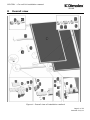
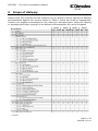
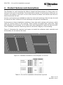
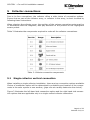
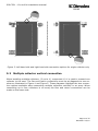
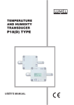
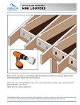
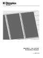
SOLAR
SOLC201 – On roof kit
Installation Manual
Page 1 of 32
R01450-2 12/11
SOLC201 – On roof kit installation manual
SOLAR
0
Overall view
Figure 1: Overall view of installation method
Page 2 of 32
R01450-2 12/11
SOLC201 – On roof kit installation manual
SOLAR
1
Contents
0
OVERALL VIEW
2
1
CONTENTS
3
2
BEFORE YOU START
4
2.1
2.2
2.3
2.4
2.5
2.6
2.7
GENERAL
COMPETENCE
HEALTH AND SAFETY
RISK ASSESSMENT
TOOLS REQUIRED
EARTHING AND LIGHTNING PROTECTION
PIPE WORK
4
4
4
5
5
5
5
3
SCOPE OF DELIVERY
6
4
PRODUCT FEATURES AND DESCRIPTIONS
7
5
COLLECTOR CONNECTIONS
8
5.1 SINGLE COLLECTOR VERTICAL CONNECTION
5.2 MULTIPLE COLLECTOR VERTICAL CONNECTION
5.3 SINGLE COLLECTOR HORIZONTAL CONNECTION
8
9
11
6
INSTALLATION
13
7
OPERATION
25
8
MAINTENANCE
25
9
DECOMMISSIONING
25
10 TECHNICAL DATA
25
Page 3 of 32
R01450-2 12/11
SOLC201 – On roof kit installation manual
SOLAR
2
2.1
Before you start
General
Thank you for choosing a Dimplex product. We ensure you that every effort has been
made at the design, manufacture and delivery stages to produce a product with superior quality. We will provide you with the best possible support throughout the product’s
lifespan.
As part of ongoing product development and improvement Dimplex reserves the right to
undertake changes to the product without prior notice. Great care has been taken to
ensure this manual was correct at the time of print. Should you however discover any
issues with the information contained therein please do not hesitate to contact your
vendor.
We strongly recommend reading the whole contents of this manual before commencing
the work.
2.2
Competence
Dimplex products have been designed and manufactured to the current relevant standards and under stringent quality control. It is therefore imperative that the product is
only installed by a:
- trained and
- competent
person as defined in the relevant regulations. Dimplex does not accept any liability for
damage done to persons or property resulting from undue handling and usage of this
product.
All regulations current at the time of installation are to be considered alongside the content of this manual as they form the code of best practice.
The warranty of this product is linked to the ability to prove that the product was installed, commissioned and maintained:
- by a competent person.
- in accordance with Dimplex instructions and the current relevant regulations and legislation.
- the product being registered with Dimplex at the time of installation using the form in
the Dimplex On Site Guide.
- records showing the date of maintenance in accordance with the maintenance schedule as detailed in the On Site Guide.
2.3
Health and Safety
The installation of this product is subject to the Health and Safety at Work Act. It is
your responsibility to ensure that the transport, storage, installation and operation of
the product are carried out in a safe manner.
Dimplex will not accept any liability due to damage caused to people or property resulting from negligence or not adhering to the relevant Health and Safety practices.
Page 4 of 32
R01450-2 12/11
SOLC201 – On roof kit installation manual
SOLAR
2.4
Risk assessment
The compilation of a risk assessment is strongly recommended before installing the
product. The following areas require particular consideration in addition to the information required by the Health and Safety at Work Act.
- scalding: where appropriate or required by law a thermostatic mixing valve is to be
fitted to the hot water outlet of the cylinder.
- explosion: the unit is fully equipped with all relevant safety equipment to comply with
current regulations. The correct design and function has been verified by independent
third party testing. The correct application thereof is the responsibility of the competent installer.
- water borne organisms (i.e. Legionella): if applicable a risk assessment should be
carried out following the recommendations outlined in the Approved Code of Practice
L8.
- the user preference must be considered when commissioning the system, in particular
when adjusting the solar and auxiliary system temperature and timer settings.
2.5
Tools required
It is recommended that the below list of tools be used when installing the Dimplex solar
collector.
-
2.6
Two people required to complete this installation
Cordless drill with 6mm wood bit,
13mm socket wrench and 14mm masonry bit
Measuring tape
Spanners, 13/17/19/20/22/30/32mm
6mm Allen Key
Angle Grinder With Stone Disc
Adjustable Pliers or Pipe Wrench
Flat Head Screw Driver
Earthing and lightning protection
If a lightning arrester is available, the collector frame should be connected to it. This
may be preformed using the collector frame, because the slot for mounting on the reverse side of the collector is ideally suited for fixing a thick cable. If no arrester is available, the potential equalization is carried out using a connection of a cable at the
tube(s) which are led in the building. Please consult local regulations to ensure adherence.
2.7
Pipe Work
The pipe work from the collector to the pump unit and from the pump unit to the cylinder is to be all metal. The joints have to be high temperature resistant (compression,
high temperature flat seal or high temperature press fitting). For more information
please see Technical Manual – Complete guide to Dimplex Solar, R00270.
Page 5 of 32
R01450-2 12/11
SOLC201 – On roof kit installation manual
SOLAR
3
Scope of delivery
Please check the contents and the condition of your delivery before signing the delivery
documentation against the content shown in Table 1 below and mark as appropriate.
Contact your supplier immediately for any missing or damaged parts. Claims for missing
or damaged parts after signing for the delivery documentation will not be accepted.
Table 1: Contents for basic and extension on roof kits
Page 6 of 32
R01450-2 12/11
SOLC201 – On roof kit installation manual
SOLAR
4
Product features and descriptions
The Dimplex on roof mounting kit offers a simple and fast solution for fixing solar collectors to the roof of a building. The kit basically consists of roof anchors which are secured to the rafters of the roof. A rail is then secured to these roof anchors and the collector fixed onto the rail.
Various roof anchors are available to cater for most roof coverings. One kit may be used
to mount the solar collectors in both landscape and portrait orientations.
Furthermore to these installation variations, there also exist various roof anchors, which
cater for various types of roof covering. These include corrugated tiles, plain tiles, slate
and sheeted roof coverings. All of which have been designed to allow for fast and efficient installation without interfering with the structural integrity of the building.
Figure 2 illustrates the required roof space to install the collectors both vertically and
horizontally for the various kit sizes.
A
A
B
B
Figure 2: Installed orientation of the Dimplex on roof kit
Table 2: On roof kit installation dimensions required
Page 7 of 32
R01450-2 12/11
SOLC201 – On roof kit installation manual
SOLAR
5
Collector connections
Due to its four connections, the collector offers a wide choice of connection options.
Ensure that no part of the collector array, or collector in the array, is short circuited by
following these instructions.
When planning the collector array, the position of the various connection parts must be
in accordance with the diagrams, also pay attention to the position of the highlighted
sensor pocket.
Table 3 illustrates the components required to make all the collector connections.
Table 3: Collector connection components
5.1
Single collector vertical connection
When installing a single collector installation, there are two connection options available.
Choice of connection option will be determined by suitability and location of the components in the solar system to one another, (pipe runs etc usually determine the choice).
Figure 3 illustrates the left hand side connection option and the right hand side connection options that are applicable only to a single vertical collector connection.
Page 8 of 32
R01450-2 12/11
SOLC201 – On roof kit installation manual
SOLAR
Figure 3: Left hand side and right hand side connection options for single collector only
5.2
Multiple collector vertical connection
When installing multiple collectors, (2 up to 4), component 10.1 is used to connect one
collector to the next. The flow and return connections must be at diagonals to one another as illustrated in Figure 4 and Figure 5. These diagrams highlight the two connection options available when connecting multiple collectors vertically in an array. When
connecting up to four collectors in an array the flow and return connections can be
made on the same side.
Page 9 of 32
R01450-2 12/11
SOLC201 – On roof kit installation manual
SOLAR
Figure 4: Multiple collector vertical connection, Option 1
The sensor pocket is inserted into the tee piece provided, as shown in Figure 4 and
Figure 5, which is on the collector flow (flow to the cylinder). The orientation of the middle collector(s) is unimportant.
Page 10 of 32
R01450-2 12/11
SOLC201 – On roof kit installation manual
SOLAR
Figure 5: Multiple collector vertical connection, Option 2
5.3
Single collector horizontal connection
When connecting a single collector horizontally, ensure the flow and return connections
are connected at the top of the collector (as illustrated).
The sensor pocket is inserted into the tee piece on the flow (flow to cylinder) pipe, as
this location will experience the highest temperatures of the collector.
Figure 6: Single collector, horizontal installation
Page 11 of 32
R01450-2 12/11
SOLC201 – On roof kit installation manual
SOLAR
Multiple collector horizontal connection
When installing multiple collectors in the horizontal position, as in Figure 7 below, it is
possible to connect the collectors in two ways. The flow and return to the array must be
connected at opposite diagonals as illustrated. When connecting up to four collectors in
an array the flow and return connections can be made on the same side.
Figure 7: Multiple collector horizontal connections, option 1 and option 2
Page 12 of 32
R01450-2 12/11
SOLC201 – On roof kit installation manual
SOLAR
6
Installation
NB: Ensure all the laths under the area of the installation are in good condition. Replace
any damaged, weak or broken laths and double nail or screw to the rafters.
Step 1.0 Vertical
For vertical installation, the rails (2/3)
are installed horizontally.
- Dimension A must be between 1.2m
and 1.6m.
- Dimensions B and C, from the rails to
the outer edge of the collector must
be between 150 and 350 mm.
- Up to 4 collectors can be connected in
series (1 basic kit and 3 extension
kits).
Step 2.0 Horizontal
For horizontal installation, the rails (2/3)
are installed vertically.
- Dimension A must be between 0.9m
and 1.6m.
- Dimensions B and C from the rails to
the outer edge of the collector must
be between 150 and 500 mm.
- Up to 4 collectors can be connected in
series (1 basic kit and 3 extension
kits).
Page 13 of 32
R01450-2 12/11
SOLC201 – On roof kit installation manual
SOLAR
Step 3.1 Corrugated Tile
- Remove one (or more) roof tiles above
the planned installation position of
each rafter anchor.
- The horizontal spacing is derived from
the rafter spacing and the vertical
spacing is derived from the roof tiles.
- The number of rafter anchors is derived from the size of the collector array (basic kit: 4 rafter anchors, extension kit: 2 rafter anchors).
Step 3.2 Corrugated Tile
- Determine the position of the rafter
anchor (5) so it is located in the
trough of the roof tile.
- Mark two fixing points on the rafter for
each rafter anchor and pre-drill them
with a 6 mm wood drill bit.
Step 3.3 Corrugated Tile
- If necessary, cut a recess in the lower
tile with an angle grinder at the point
where the rafter anchor comes
through.
- Pay particular attention to the leaktightness of the roof at the position
where the rafter anchor comes
through. The roof hook must not exert
any pressure on the roof tile.
Page 14 of 32
R01450-2 12/11
SOLC201 – On roof kit installation manual
SOLAR
Step 3.4 Corrugated Tile
- Fix each rafter anchor (5) to the roof
rafters with 2 wood screws (6.1) and
washers (6.3).
- The screws (6.1) must enter into the
wood to a depth of at least 40 mm.
- The rafter anchors (5) must not rest
on the roof tiles! A spacing of 5 mm
must be kept between the rafter and
the roof tile. If necessary, underlay
the rafter anchors with equalisation
boards (6.6).
Step 3.5 Corrugated Tile
- Cut a recess in the upper tile with an
angle grinder at the point where the
rafter anchor comes through.
Step 3.6 Corrugated Tile
- Replace the upper roof tile.
- Pay particular attention to the leaktightness of the roof at the position
where the rafter anchor comes
through. The roof tile must not be
pushed up by the rafter anchor (5).
- The remaining rafter anchors are to be
installed in a similar way.
Page 15 of 32
R01450-2 12/11
SOLC201 – On roof kit installation manual
SOLAR
Step 4.1 Plain Tile
- Remove one (or more) roof tiles above
the planned installation position of
each rafter anchor.
- The horizontal spacing is derived from
the rafter spacing and the vertical
spacing is derived from the roof tiles.
- The number of rafter anchors is derived from the size of the collector array (basic kit: 4 rafter anchors, extension kit: 2 rafter anchors).
Step 4.2 Plain Tile
- Determine the position of the rafter
anchor (13) so it is located on a roof
rafter directly above the batten.
- Mark two fixing points on the roof rafter for each rafter anchor and pre-drill
them with a 6 mm wood drill bit.
Step 4.3 Plain Tile
- Fix each rafter anchor (13) to the roof
rafters with 2 wood screws (6.1) and
washers (6.3).
- The screws (6.1) must enter into the
wood to a depth of at least 40 mm.
- The rafter anchors (13) must not rest
on the roof tiles! A spacing of 5 mm
must be kept between the rafter and
the roof tile. If necessary, underlay
the rafter anchors with equalisation
boards (6.6).
Page 16 of 32
R01450-2 12/11
SOLC201 – On roof kit installation manual
SOLAR
Step 4.4 Plain Tile
- It may be necessary to cut a recess in
the plain tile, in the position of the rafter anchor.
- This is done so by using an angle
grinder. Ensure that the tile is seated
in position and is tight around the rafter anchor.
Step 4.5 Plain Tile
- Replace the roof tile(s).
- Pay particular attention to the leaktightness of the roof at the position
where the rafter anchor comes
through.
- The remaining rafter anchors can be
installed in the same fashion.
Step 5.1 Slate
- Remove one (or more) slates above
the planned installation position of
each rafter anchor.
- The spacing to the side is derived from
the rafter spacing and the number of
rafter anchors.
- The spacing between the rails must be
observed as described in steps 1.0
and 2.0.
Page 17 of 32
R01450-2 12/11
SOLC201 – On roof kit installation manual
SOLAR
Step 5.2 Slate
- Determine the position of the rafter
anchor (13) so that it is located on a
roof rafter directly above a roof batten.
- Mark two fixing points on the roof rafter for each rafter anchor and pre-drill
them with a 6 mm wood drill bit.
Step 5.3 Slate
- Fix each rafter anchor (13) to the roof
rafters with 2 wood screws (6.1) and
washers (6.3).
- The screws (6.1) must enter into the
wood to a depth of at least 40 mm.
- The rafter anchors (13) must not rest
on the slates! A spacing of 5 mm must
be kept between the rafter and the
slates. If necessary, underlay the rafter anchors with equalisation boards
(6.6).
Step 5.4 Slate
- The slates are laid as per usual. However, it may be required to cut the
slates in order for them to fit around
the roof anchor.
- Minimal cuts where possible should be
made and unnecessary cuts avoided.
Page 18 of 32
R01450-2 12/11
SOLC201 – On roof kit installation manual
SOLAR
Step 5.5 Slate
- A piece of lead is secured to the batten
above the roof anchor.
- This lead slate should be formed
tightly around the roof anchor, preventing any rain water etc entering
the building around the roof anchor.
- The lead slate should be at least the
same size as the roof slates being
used.
Step 5.6 Slate
- The remaining slates are positioned in
the usual fashion.
- Cut outs may be necessary to fit the
slates around the roof anchor however
it is important that the water tightness
of the building is sustained.
- The remaining roof anchors must be
installed in the same fashion.
Step 6.1 Sheet Roof
- Pre-drill the sheeted roof at the crest
(where applicable) with a ø14 mm drill
bit.
- The spacing to the side is derived from
the rafter spacing and the number of
rafter anchors.
- The spacing between the rails must be
observed as described in steps 1.0
and 2.0.
- Do not drill the rafters!
Page 19 of 32
R01450-2 12/11
SOLC201 – On roof kit installation manual
SOLAR
Step 6.2 Sheet Roof
- Pre-drill the rafters through the hole in
the sheeted roof with an ø6 mm wood
drill bit.
Step 6.3 Sheet Roof
- Insert the hanger bolt (14.1) through
the hole in the sheeted roof and screw
it into the pre-drilled rafter.
- The hanger bolt must not exert any
pressure on the sheeted roof!
Step 6.4 Sheet Roof
- Seal the hole on the crest of the roof
covering with seal (14.3).
- To do so, slide the seal with the flat
side facing upwards onto the hanger
bolt (14.1) up to the level of the
sheeted roof.
- Next, carefully secure the seal with an
M10 hexagonal nut (14.2).
Page 20 of 32
R01450-2 12/11
SOLC201 – On roof kit installation manual
SOLAR
Step 6.5 Sheet Roof
- Attach the rail holder (14.4) to the
hanger bolt (14.1) using two M10 hexagonal nuts (14.2).
Step 7.1 Roof Rails
- According to the number of rafter
anchors (5/13/14), feed an M10 hexagonal bolt (6.2) with a slot nut (6.5)
into the rail (2/3).
- The rails can be pre-assembled on the
ground.
Step 7.2 Roof Rails
- Extend the rail (2/3) with a rail connector (7.1).
- To do so, slide the rail connector into
the ends of two rails (2/3) and screw
it in place with two M8 hexagonal
bolts (7.2) and M8 hexagonal nuts
(7.4) with washers (7.3).
Page 21 of 32
R01450-2 12/11
SOLC201 – On roof kit installation manual
SOLAR
Step 7.3 Roof Rails
- Fix two rail end sets (8) to one side of
the collector array.
- Attach one rail end piece – consisting
of a rail connector (8.1) and the end
piece (8.2) – per rail string as a stop
for the first collector (1).
- To do so, slide the assembled end
piece into the rail (2/3) and screw it
in place with an M8 x 50 hexagonal
bolt (8.3), a washer (8.4) and an M8
hexagonal nut (8.5).
Step 8.1 Vertical
- Lock the lower rail (2/3) into the rafter
anchor (5/13/14) or rail holder (14.4).
Mount the rail with the flanged end
facing up the roof, as illustrated.
- Position the M10 hexagonal bolt (6.2)
with slot nut (6.5) in the rail according
to the positions of the rafter anchors
and fix it to the rafter anchor
(5/13/14) by hand with a washer
(6.3) and an M10 hexagonal bolt
(6.4).
Step 8.2 Vertical
- Attach the upper rail (2/3) as described in steps 1 to 3 and position it
sideways.
- Position the rails with respect to each
other so that the diagonals D and E
are of equal length. Mark the correct
position before installing them. Next,
fasten both rails in place by tightening
the M10 hexagonal bolts (6.4).
- The rail end sets (8) must be on the
side where the first collector is to be
installed.
Page 22 of 32
R01450-2 12/11
SOLC201 – On roof kit installation manual
SOLAR
Step 9.1 Horizontal
- Mount the first rail (2/3). Lock the
stud into the mounting profiles (4.2),
- Align towards the planned position of
the collector connections.
- Position the M10 hexagonal bolt (6.2)
with slot nut (6.5) in the rail according
to the positions of the rafter anchors
and fix it to the rafter anchor
(5/13/14) by hand with a washer
(6.3) and an M10 hexagonal bolt
(6.4).
Step 9.2 Horizontal
- Attach the second rail (2/3) as described in steps 1 to 3 and position it
vertically.
- To do so, position the rails with respect to each other so that the diagonals D and E are of equal length.
- Mark the correct position before installing them.
- Next, fasten both rails in place by
tightening the M10 hexagonal bolts
(6.4).
- The rail end pieces (8) must be at the
bottom end of the rails.
Page 23 of 32
R01450-2 12/11
SOLC201 – On roof kit installation manual
SOLAR
Step 10.1 Collectors
- Position the square nuts in the slot on
the back of the collector with a
screwdriver and secure them with the
installation aid (4.4).
- Using the installation aid, the square
nut can easily be positioned for further installation of the fixing profile
(4.2) when the collector (1) has been
erected.
Step 10.2 Collectors
- Preassemble the mounting profile
(4.2) with an M8 hexagonal bolt (4.1)
and washer (4.3) on the square nuts
on the rear side of the collector.
- When installing the mounting profiles,
pay attention to the planned orientation of the collector on the roof (and
thus the position of the sensor pockets). See Chapter 5 on collector connections.
Page 24 of 32
R01450-2 12/11
SOLC201 – On roof kit installation manual
SOLAR
Step 10.3 Collectors
- Determine the definitive lower spacing
C of the mounting profiles (4.2) on
the collector.
- To do so, keep a distance of 150350 mm between the lower edge of
the collector and the lower mounting
profile for vertical installation and
150-500 mm for horizontal installation.
- Attach the upper mounting profiles in
accordance with the spacing A of the
rails (2/3) to the lower mounting rails.
- The distance B to the top edge of the
collector must also be within the
range given above.
- The mounting profiles must be facing
downwards. Preassemble the securing
screw (4.5) 100mm beneath the lower
mounting profiles.
Step 10.3.1 Collectors
- Extension kit: When installing the
mounting profiles for vertical installation, use the dimensions from the basic kit collectors for the spacing’s C.
- The mounting profiles (4.2) must be
facing outwards so that the collector
can be positioned onto the rails (2/3).
- Preassemble the upper mounting profiles for security. The spacing A is derived from the rail spacing plus 5mm.
The upper mounting profiles must be
pointing downwards and are only put
in their final position once they are on
the roof.
- Preassemble the securing screw (4.5)
beneath the lower mounting profiles.
Page 25 of 32
R01450-2 12/11
SOLC201 – On roof kit installation manual
SOLAR
Step 10.4 Collectors
- Punch the two drainage holes at each
bottom corner of the collector, (according to how it is positioned on the
roof).
- A flat head screwdriver may be used,
punch the bottom edges out, as illustrated across.
- This will ensure any water can drain
properly from the collector.
Step 11.0 Vertical
- Carefully lift the collector onto the
rails.
- Position the collector against the rail
end sets (8) and slowly let it slide
downwards until the mounting profiles (4.2) lock into the rails.
- Next, position the securing screws
4.5) against the rail from underneath
and tighten it.
Step 12.0 Horizontal
- Carefully lift the collector onto the
rails.
- Position the collector. To do so, let
the collector slowly slide downwards
against the rail end sets (8) and
move it sideways until the mounting
profiles (4.2) lock into the rails.
- Next, position the securing screws
4.5) against the rail from the side and
tighten it.
Page 26 of 32
R01450-2 12/11
SOLC201 – On roof kit installation manual
SOLAR
Step 13.0 More collectors
When installing more collectors:
- For both horizontal and vertical installation, first stick the spacer (7.5) onto
the rails with the stopper against the
first collector.
- The next collector must be positioned
next to the spacers.
- Insert 2 support sleeves (11.2) into
the collector pipes which are to be
connected. Attach the compression fitting (11.1) to the collector pipes.
Step 14.1 Vertical
- Position the next collector on the
lower outward facing mounting profiles (4.2) on the lower rail (3) and
feed it onto the compression fitting by
moving the collector on the rails (3).
Before doing so, insert 2 support
sleeves (11.2) into the collector pipes.
- To ensure the collector is adequately
secured, the upper mounting profiles
(4.2) must engage in the rail (3).
Step 14.2 Vertical
- Lock the upper mounting profiles (4.2)
into the upper rail and screw in place.
Rotate the lower mounting profile 90°,
lock it into the lower rail and screw it
in place.
- Next position the securing screw (4.5)
against the rail from underneath and
tighten it.
Page 27 of 32
R01450-2 12/11
SOLC201 – On roof kit installation manual
SOLAR
Step 15.0 Horizontal
- Position the next collector on the rails
(3) and move it sideways until the
mounting profile (4.2) look into the
rails. Let the collector slowly slide
downwards and insert the collector
pipes into the compression fitting. Before doing so insert 2 support sleeves
into the collector pipes.
- Next position the securing screws
(4.5) against the rail from the side
and tighten it.
- Insert the collector pipes fully into the
screw fitting (11.1). Do not overtighten the connection (hand tight +
¾ spanner turn). Use two spanners so
that there is no tension on the absorber.
- After installing the last collector, attach two rail end pieces (8) to the
open end of the rails (2/3).
Step 16.1 Connections
- Because of its 4 connections, the collector offers a wide choice of connection options. Ensure that no part of
the collector array or collector in the
array is short circuited.
- When planning the collector array, the
position of the various connection
parts must be in accordance with the
diagrams. The numbering in the diagrams corresponds with the numbering in the parts list.
- To connect the collectors on the right
hand side, mount the frame joint on
top. To connect the collectors on the
left hand side, mount the frame joint
on the bottom.
Page 28 of 32
R01450-2 12/11
SOLC201 – On roof kit installation manual
SOLAR
Step 16.2 Connections
- To ensure the full flow-through of the
collector array, the positions of the
frame joints must be observed!
- This diagram shows how to connect 3
collectors with the positions of the
parts of the connection and joining kit
(10/11) (the position of the frame
joints must be observed here as
well).
- For installing two collectors, the con-
nections correspond with the outer
collectors. The collector in the middle
is omitted in this case. If more collectors are to be connected directly to
the collector array, an extension kit
must be used.
Step 16.3 Connections
- To install the sensor, the sensor
pocket (10.5) must be screwed into
the female tee (10.4). Please note
that this is the hottest point in the solar circuit and the sealing material
used to seal the sensor pocket into
the t-piece must be suitable. PTFE
tape is not recommended. Ideally a
hemp based compound is used ensuring that the flow is not affected.
- The sensor is then inserted into the
sensor pocket (10.5) and the screw at
the side of the sensor pocket is tightened to hold the sensor in place.
Page 29 of 32
R01450-2 12/11
SOLC201 – On roof kit installation manual
SOLAR
Step 17.1 Pipe Work
- Replace one roof tile with a ventilation
tile (feed through tile) above the feedthrough of each connecting pipe.
- Next feed the connecting pipes
through the ventilation tile into the interior of the building.
- The piping should be laid so that it
rises upwards in order to allow ventilation at the highest point of the solar
energy system.
Step 17.2 Pipe Work
- Install the connecting pipes to each of
the external collector connections. Use
the support sleeves (10.3). Attach the
end pieces (10.2) with support sleeves
(10.3) to the open collector pipe ends
and tighten.
- Do not overtighten the compression
fitting (hand tight + ¾ spanner turn).
Use two spanners so that there is no
tension on the absorber.
Page 30 of 32
R01450-2 12/11
SOLC201 – On roof kit installation manual
SOLAR
7
Operation
Although there are no operational components in the on roof kit, the fixings should be
double checked prior to commissioning of the system.
Please refer to the On Site Guide for guidance on how to commission and operate the
solar system.
8
Maintenance
Risk of scalding! Before carrying out any maintenance work on the system, ensure that
it is safe to do so. The solar system must be decommissioned before work can be carried out.
Refer to the On Site Guide for a maintenance schedule of the complete system. However some basic checks can be made, for example, check for leaks at the collector connections and other connections in the system. Also ensure pipe insulation is intact and
in good condition.
9
Decommissioning
Risk of scalding! Before carrying out any decommissioning work on the on roof kit,
please ensure the solar system has been decommissioned.
If the product is being recycled, local waste disposal laws must be adhered to.
10 Technical Data
Page 31 of 32
R01450-2 12/11
SOLC201 – On roof kit installation manual
SOLAR
Page 32 of 32
R01450-2 12/11