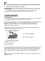
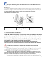
1
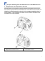
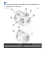
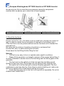
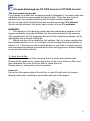
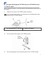
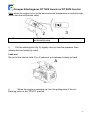
FRANCEPOW ER 147 bis rue de Merville BP 30212 59524 HAZEBROUCK Cedex Email : f ran ce-pow er @w an adoo.f r L’énergie facile ! Tél (33) 03 28 50 92 30 Fax (33) 03 28 50 92 31 Sit e : w w w .f ran cepow er.f r MANUEL D’UTILISATION ET D’ENTRETIEN USE AND MAINTENANCE MANUAL GROUPES ÉLECTROGENES INVERTER FP 1000 Inverter FP 2000 Inverter Code 01900 Code 01910 Traduction de l’Original Groupes Electrogènes FP 1000 Inverter et FP 2000 Inverter Notice d’Utilisation Lisez attentivement ce manuel avant de vous servir du générateur. Ces instructions contiennent des directives de fonctionnement importantes au plan de la sécurité. 2 Groupes Electrogènes FP 1000 Inverter et FP 2000 Inverter DECLARATION DE CONFORMITE Je soussigné FRANCEPOWER SARL, 147 BIS RUE DE MERVILLE - 59190 HAZEBROUCK – France ATTESTE QUE LE GROUPE ELECTROGENE EST CONFORME AUX CONDITIONS ESSENTIELLES DE SECURITE ET DE PROTECTION DE LA SANTE VISEES DANS LES DIRECTIVES 2006/42/CE, 2004/108/CE, 2006/95/CE et 2000/14/CE ET DANS LA NORME NF EN 12601 :2010. Fait à HAZEBROUCK Dominique LAMBIN Le 2 Septembre 2011 Gérant 3 Groupes Electrogènes FP 1000 Inverter et FP 2000 Inverter Préface Merci d’avoir acheté ce groupe électrogène Inverter Ce manuel vous donne les instructions de fonctionnement et de maintenance du FP 1000 Inverter et du FP 2000 Inverter. Le contenu de ce manuel correspond aux caractéristiques du produit le plus récent. L’entreprise se réserve le droit de modifier ce manuel, sans avoir à en notifier les utilisateurs ni engager sa responsabilité. Toute reproduction est interdite, sauf accord écrit. Le manuel est considéré comme un élément permanent du générateur et doit donc être conservé avec la machine en cas de transfert. Merci d’accorder une attention particulière aux termes suivants : Cette mention indique qu’en cas de non respect des instructions d’exploitation du manuel, il y a des risques d’accidents susceptibles de causer des blessures graves. Attention : cette mention indique qu’en cas de blessure ou de dégâts sur l’équipement causés par un mauvais fonctionnement, vous pouvez contacter votre revendeur pour toute question concernant le générateur. Remarque : informations utiles. En cas de défaillance du générateur ou pour toute autre question le concernant, consultez votre revendeur. Tant que vous respectez les instructions du manuel, le groupe électrogène FP 1000 Inverter ou FP 2000 Inverter fonctionnera en toute sécurité et restera fiable. Assurez-vous de bien lire et comprendre le mode d’emploi complet avant d’utiliser l’appareil, car une mauvaise exploitation pourrait causer des blessures et des dégâts matériels. Les différents types de générateurs pourront présenter des différences au niveau des instructions. 4 Groupes Electrogènes FP 1000 Inverter et FP 2000 Inverter 5 Groupes Electrogènes FP 1000 Inverter et FP 2000 Inverter Sommaire 1. Sécurité 2. Emplacements des étiquettes de sécurité 3. Identifiant des composants 4. Vérification avant Mise en marche 5. Mise en marche (fonctionnement en altitude) 6. Utilisation 7. Arrêt du moteur, maintenance 8. Transport/stockage 9. Indentification et réparation de pannes 10. Spécification technique 11. Schéma de principe 6 Groupes Electrogènes FP 1000 Inverter et FP 2000 Inverter 1. Sécurité Pour votre sécurité, il est important de respecter les consignes qui suivent. Si vous faites fonctionner le groupe électrogène FP 1000 Inverter ou FP 2000 Inverter conformément au manuel, il fonctionnera en toute sécurité. Veillez à bien lire la notice et à l’assimiler avant d’utiliser l’appareil pour la 1ère fois car une mauvaise exploitation pourrait causer des blessures et des dégâts matériels. Les gaz d’échappement contiennent du CO toxique. Ne faites pas marcher le groupe électrogène dans un espace clos. Assurez-vous que la ventilation est suffisante. Le carburant s’enflamme ou explose très facilement dans certaines conditions. Arrêtez le moteur avant de faire le plein. Lorsque vous faites le plein, évitez de fumer et de produire des étincelles. Veillez à l’aération. Nettoyez immédiatement tout déversement de carburant. Avant chaque démarrage du moteur, procédez à une inspection, afin d’éviter les accidents ou des dégâts sur les équipements. Le groupe électrogène doit se trouver à au moins 1 mètre des bâtiments et des autres équipements lorsqu’il fonctionne. Le groupe électrogène doit fonctionner sur une surface horizontale. Si ce n’est pas le cas, le carburant risque de se déverser à l’extérieur. Vous devez savoir comment procéder à un arrêt rapide du groupe, et également savoir comment commander tous ses éléments. Ne faites jamais fonctionner le moteur sans avoir les instructions correctes à disposition. Les enfants et animaux domestiques devront être éloignés de la zone de fonctionnement. Lorsque le moteur est en marche, personne ne doit s’approcher des parties mobiles. Le groupe représente un risque s’il n’est pas exploité correctement, évitez de le faire fonctionner manuellement. Ne faites pas fonctionner le groupe sous la pluie ou la neige, il doit rester au sec. 7 Groupes Electrogènes FP 1000 Inverter et FP 2000 Inverter 2. Emplacements des étiquettes de sécurité Ces étiquettes vous signalent les dangers latents susceptibles de provoquer des accidents graves entrainant des blessures. Lisez attentivement le texte des étiquettes, les avertissements de sécurité et les remarques rappelées dans le mode d’emploi. Si les étiquettes ont disparu ou sont illisibles, contactez votre revendeur afin de les remplacer. 1 – Etiquette de niveau d’huile 3 – Etiquette d’avertissement 2 – Interrupteur moteur 8 Groupes Electrogènes FP 1000 Inverter et FP 2000 Inverter 3. Identification des composants A – Starter C - Bouchon de réservoir de carburant E – Interrupteur du moteur G – Capot d’accès pour réparation I - Silencieux B – Bouton de ventilation réservoir de carburant D – Panneau de commande F – Poignée du lanceur H – Couvercle de bougie 9 Groupes Electrogènes FP 1000 Inverter et FP 2000 Inverter Panneau de commande : 1 – Interrupteur de l’économiseur d’essence 3 – Voyant de surcharge 5 – Prise de courant 220V CA 7 – prise de courant 12 V CC 2 – Voyant de marche 4 – Voyant d’alerte carburant 6 – Borne de Terre 8 – Protection prise L’appareil est doté d’un affichage intelligent : en fonctionnement, il indique la tension, la fréquence et la puissance consommée. Ces indications sont utiles pour éviter les surcharges Vanne intelligente d’économie de carburant : Lorsque le moteur est débranché de l’équipement électrique, la vitesse du groupe chute automatiquement. Lorsque l’équipement est branché, la charge électrique permet au groupe de revenir à une vitesse de rotation appropriée. Cette installation sert à réduire la consommation de carburant pendant l’exploitation. 10 Groupes Electrogènes FP 1000 Inverter et FP 2000 Inverter Le robinet économiseur d’essence ne peut fonctionner que si un appareil électrique 220V est relié au groupe. Lorsque le groupe est branché avec une forte charge électrique, coupez la vanne intelligente d’économie de carburant afin de minimiser les variations de pression moyenne. Si vous utilisez la sortie 12V, fermez le robinet économiseur. En position OFF: Le robinet économiseur d’essence est fermé et la vitesse de rotation du groupe est maintenue à un niveau supérieur à la vitesse de rotation standard. 11 Groupes Electrogènes FP 1000 Inverter et FP 2000 Inverter 4. Vérification avant mise en marche Avertissement Contrôlez le groupe, il doit absolument se trouver sur une surface horizontale. Assurez-vous également que le moteur est coupé. 1. Contrôle du niveau d’huile Avertissement Si vous utilisez une huile sans purifiant ou une huile pour moteur 2 temps, vous risquez de réduire la durée de vie de votre groupe. Utilisez une huile contenant un fort taux d’agent nettoyant ou une huile moteur 4 temps de qualité supérieure. Le niveau de qualité doit correspondre ou dépasser le niveau SG/SF exigé par le fabricant américain et défini par l’American Petroleum Institute. Choisissez une huile de moteur dont le degré de viscosité sera adapté aux températures de la région où vous vivez. Légendes Ordre de degré de viscosité SAE 1 degré de viscosité simple 2 degré de viscosité multiple Température ambiante Enlevez la jauge d’huile, essuyez-la avec un chiffon et plongez-la dans le tube de contrôle pour vérifier le niveau d’huile. Veillez à ne pas laisser tomber la jauge dans ce tube. Si le niveau de l’huile se trouve en dessous du bas de la jauge, versez l’huile de machine adaptée dans le tube de remplissage. Le moteur risque de fortement s’abîmer s’il fonctionne sans huile ou avec trop peu d’huile. 12 Groupes Electrogènes FP 1000 Inverter et FP 2000 Inverter Remarque : Le système d’alarme d’huile arrête le moteur avant que le niveau ne passe en dessous de la ligne de sécurité. Mais pour éviter les désagréments causés par un arrêt inattendu de la machine, nous vous conseillons de vérifier régulièrement le niveau d’huile. 1 – Bouchon d’huile 2 – Orifice de remplissage d’huile 3 – Niveau d’huile maximum 2. Contrôle du niveau de carburant : Utilisez de l'essence automobile. (Il vaut mieux utiliser un carburant sans plomb, ou à basse teneur en plomb, afin de réduire l’accumulation de charbon dans la chambre de combustion.) Si le niveau de carburant est trop bas, ajoutez du carburant jusqu’à ce que le niveau requis soit atteint dans le réservoir. N’utilisez jamais de mélange d’huile et d’essence, ni de carburant comportant des impuretés. Empêchez la saleté, la poussière et l’eau de pénétrer dans le réservoir. Une fois le plein fait, revissez fermement le bouchon de réservoir de carburant. Le carburant s’enflamme ou explose très facilement dans certaines conditions. Remplissez le groupe dans un endroit aéré et stoppez le moteur avant le remplissage. Il est strictement interdit de fumer à proximité des zones de remplissage et de stockage de carburant de générateur. Veillez à ne pas renverser de carburant à l’extérieur du réservoir (il faut éviter la présence de carburant sur l’embouchure de remplissage). Une fois le plein fait, revissez fermement le bouchon de réservoir de carburant. Lorsque vous remplissez le groupe, veillez à éviter tout débordement. Le 13 Groupes Electrogènes FP 1000 Inverter et FP 2000 Inverter carburant renversé ou les vapeurs de carburant peuvent s’enflammer. S’il y a déversement d’essence, assurez-vous que la zone où elle a été déversée est bien nettoyée avant la mise en marche du moteur. Evitez un contact prolongé du carburant avec votre peau et tous contacts répétés. Les enfants ne doivent pas toucher le carburant. Bio Carburants Si vous décidez d’utiliser un carburant contenant de l’alcool (bioéthanol), il ne faut pas que son indice d’octane soit inférieur au niveau conseillé par le fabricant. Il existe deux types d’alcool carburants : ceux à l’éthanol et ceux au méthanol. N’utilisez pas de carburant contenant plus de 10% d’éthanol. N’utilisez pas de carburant contenant plus de 5% de méthanol. Les dégâts causés au système de combustion de carburant ainsi que les problèmes de performance du moteur en cas d’utilisation carburant contenant une trop forte proportion d’alcool ne sont pas couverts par la garantie. Le fabricant ne couvre pas non plus l’utilisation d’un carburant au méthane, car son applicabilité n’a pas été confirmée. Avant d’acheter du carburant chez de nouveaux pompistes, essayez de vous renseigner pour savoir si le carburant contient de l’alcool ou non. Dans l’affirmative faites vous confirmer le type et le taux d’alcool dans le carburant. Si vous utilisez un carburant contenant de l’alcool ou si vous pensez qu’il en contient, et si des évènements imprévus se produisent pendant l’exploitation, passez à une utilisation de carburant sans alcool. 3. Contrôle du filtre à air Contrôlez le support de filtre à air, pour vérifier qu’il soit propre et fonctionne bien. Démontez le capot d’accès pour réparation, desserrez la vis du couvercle de filtre à air, puis démontez le couvercle du filtre à air pour vérifier le support. Nettoyez ou remplacez le support si nécessaire. Attention Ne faites pas fonctionner le moteur sans filtre à air, car des particules de saleté pénétreront dans le moteur par le carburateur et entraineront une usure rapide du moteur. 14 Groupes Electrogènes FP 1000 Inverter et FP 2000 Inverter A – Vis du cache C – Filtre à air E – Vis du filtre à air B – Capot d’accès pour réparation D – Couvercle du filtre à air F – Support du filtre à air 15 Groupes Electrogènes FP 1000 Inverter et FP 2000 Inverter 5. Démarrez le moteur Avant de démarrer le moteur, coupez la charge provenant de la prise de courant alternatif sur le moteur. a) Positionnez l’obturateur complètement sur « OUVERT » en tournant en sens horaire. Remarque : lorsque vous transportez le moteur, tournez la tige de ventilation du couvercle de chambre de combustion sur la position « FERMÉ ». 1 – Bouton de ventilation du réservoir 2 – Interrupteur du moteur de carburant b) Tournez l’interrupteur du moteur pour le placer sur « OUVERT » c) Tournez la commande d’obturation d’air (Starter) et placez-la sur « FERMÉ » 16 Groupes Electrogènes FP 1000 Inverter et FP 2000 Inverter Remarque : lorsque le moteur est chaud ou que la température ambiante est relativement élevée, n’utilisez pas le starter. 1 – Fermé 2 –Manette de starter 3 - Fermé d) Tirez la poignée de démarrage (fig. A) légèrement jusqu’à ce que vous sentiez une résistance, puis relâchez lentement la poignée. Attention Ne laissez pas rebondir la poignée de démarrage (Fig. A), mais relâchez- la lentement à la main. e) Lorsque le moteur chauffe, positionnez le starter sur «DEMARRAGE». 17 Groupes Electrogènes FP 1000 Inverter et FP 2000 Inverter 1 – Marche 2 – Starter 3 - Démarrage Attention Si le moteur ne redémarre pas après avoir calé, vérifiez en priorité le niveau d’huile. Fonctionnement en altitude En altitude, le mélange d’air et de carburant standard du carburateur va devenir très dense et provoquer un ralentissement du fonctionnement du moteur et un accroissement de la consommation de carburant. Pour améliorer les performances du moteur en altitude, on peut procéder à des réglages spéciaux sur le carburateur. Si vous devez utiliser le moteur à une altitude supérieure à 1500 mètres (5000 pieds), demandez à l’agent agréé de modifier le carburateur. Même avec le bon gicleur, la puissance du moteur se réduira de 3,5% tous les 300 mètres (1000 pieds) vers le haut. En l’absence des réglages de modification, l’altitude aura un impact encore plus important sur la puissance. Attention Le gicleur du moteur est conçu pour des zones d’altitude normale. Si vous l’utilisez dans des zones de très haute altitude, la puissance de fonctionnement baissera et il y aura surchauffe, et le moteur risque de subir des dommages importants car la proportion d’air et de carburant en combustion sera trop faible. 18 Groupes Electrogènes FP 1000 Inverter et FP 2000 Inverter 6. Utilisation du moteur Si toutes les installations raccordées ont été mises à la terre, vérifiez que le moteur est également à la terre. Pour éviter tout choc électrique causé par une manipulation incorrecte, le moteur doit être mis à la terre. La prise de terre du moteur et la source externe de terre sont raccordées par un câble épais. En cas d’utilisation comme puissance accessoire pour des bâtiments, il faut que la connexion entre le générateur et les autres systèmes de puissance électrique soit faite par des électriciens professionnels. Il faut aussi respecter les réglementations et lois locales sur l’électricité. Faute de quoi, le courant du moteur risque d’être réinjecté dans le circuit public. Et dans ce cas, si les ouvriers de la compagnie de fourniture d’électricité ou d’autres personnes touchent le câble alors qu’il transmet de l’électricité, ils risquent une électrocution fatale. Par ailleurs, si la puissance électrique du réseau public est stockée, le moteur risque de brûler, d’exploser, ou de causer l’incendie des systèmes électriques du bâtiment. 1 – Symbole de la terre 2 – Borne de terre Attention Ne dépassez pas la puissance nominale et prenez en compte le wattage total de tous les appareils branchés. Ne dépassez pas la limite de courant fixée de la prise. Ne raccordez pas le moteur au circuit domestique sous peine 19 Groupes Electrogènes FP 1000 Inverter et FP 2000 Inverter d’endommager le moteur ou le circuit domestique. Ne modifiez pas le moteur pour vous en servir pour d’autres buts. Respectez les règles suivantes : Si vous voulez prolonger le câble, utilisez un câble souple avec une gaine de caoutchouc (selon IEC245 ou exigences applicables). Exigences de prolongation du câble : 60 mètres pour 1 mm² et 100 mètres pour 2,5 mm². Si le câble est trop long, sa résistance intérieure va augmenter au point que la puissance électrique applicable va se réduire. Le générateur doit être éloigné des autres conducteurs et câbles, tels que les circuits de fourniture d’électricité professionnelle. Les sources de courant alternatif CA et de courant continu CC peuvent être utilisées simultanément. Si vous souhaitez utilisez le CA et le CC simultanément, assurez-vous que la puissance électrique totale ne dépasse pas la somme du courant alternatif et direct. Rappel ! La puissance de démarrage des appareils électriques est supérieure à la puissance nominale dans la plupart des cas. Emploi du courant alternatif 1 Démarrez le moteur et vérifiez que le voyant lumineux (vert) s’allume. 2 Vérifiez que l’interrupteur de l’appareil électrique à utiliser est sur arrêt avant de le brancher au générateur. 3. Démarrez l’équipement A – Voyant de surcharge B – Voyant d’alerte carburant C – Prise 220V 20 Groupes Electrogènes FP 1000 Inverter et FP 2000 Inverter Attention Lorsque l’appareil électrique est branché au groupe, vérifiez que l’équipement fonctionne bien avant de raccorder. Si l’appareil ne fonctionne pas normalement, si la vitesse décroit ou si l’appareil arrête subitement de fonctionner, il faut immédiatement arrêter le moteur, le débrancher du circuit, et l’examiner pour trouver la panne. Les voyants de marche et de surcharge Si le groupe fonctionne bien, le voyant de marche (vert) est allumé. Si le groupe est en surcharge (plus de 2KVA), ou en cas de court-circuit dans l’installation électrique à laquelle il est relié, le voyant de marche (vert) s’éteint, et le voyant de surcharge (rouge) s’allume. Le courant devant aller vers l’appareil électrique sera alors coupé. Si le voyant est au rouge, arrêtez le moteur et déterminez pourquoi il est en surcharge. Avant de relier le conducteur au groupe, examinez-le pour vérifier qu’il est en bon état et pour vérifier si sa puissance électrique dépasse ou non la capacité du générateur. Vous pouvez alors brancher le câble de l’appareil électrique et démarrer le groupe. 1 – Surcharge (ROUGE) 2 – Marche (VERT) Juste au démarrage du groupe, les voyants rouge et vert risquent de s’allumer tous les deux. Si le rouge s’éteint, c’est normal, mais s’il reste allumé, questionnez votre revendeur. Utilisation du courant continu La prise de courant continu CA est destinée uniquement à la charge de la batterie (12V). 21 Groupes Electrogènes FP 1000 Inverter et FP 2000 Inverter Attention Durant le processus de courant direct, positionnez la vanne intelligente d’économie de carburant sur « FERMÉ ». Raccordez d’abord le câble de charge (Fig. A) à la prise de courant direct du générateur Puis reliez-la au côté de raccordement de la batterie. Démarrez le moteur Pour prévenir l’apparition d’étincelles autour de la batterie, reliez d’abord le fil de charge au groupe, puis à la batterie. il faut démonter à partir de la batterie. Avant de connecter le fil de charge à la batterie installée sur le véhicule, débranchez d’abord le fil de terre de la batterie. Ne branchez pas le fil de terre de la batterie avant que le câble de charge ne soit démonté. Ceci permettra de prévenir tout court-circuit ou étincelle lors d’un éventuel contact inopiné avec le côté de raccordement de la batterie, le châssis ou la caisse du véhicule. Attention Ne tentez pas de démarrer le moteur du véhicule alors que le groupe est encore connecté aux batteries, afin de ne pas endommager celui-ci. Le pôle positif du câble de charge ne doit pas être raccordé au pôle négatif de la batterie. N’inversez pas la polarité du câble de charge, vous risqueriez de causer des dégâts importants sur le générateur et la batterie. La batterie dégage un liquide explosif, il faut donc l’éloigner de toutes étincelles, flammes ou cigarettes. Chargez dans un espace ventilé. La batterie contient de l’acide (cellule électrolytique). En cas de contact avec la peau ou les yeux, il y aura brûlure. Portez des vêtements et un masque de protection. Si vous recevez des gouttes d’électrolyte sur la peau, lavez immédiatement à l’eau. Si vous recevez des gouttes d’électrolyte dans les yeux, lavez immédiatement à l’eau pendant au moins 15 minutes et rendez vous chez un 22 Groupes Electrogènes FP 1000 Inverter et FP 2000 Inverter médecin. L’électrolyte est toxique. Si vous en avalez, buvez immédiatement une grande quantité d’eau ou de lait. Puis buvez une solution de magnésie ou de l’huile végétale, et rendez vous chez un médecin. Les enfants doivent être tenus à distance. Attention La prise de courant direct peut être appliquée lorsque vous utilisez du courant alternatif. Il se peut que le contacteur de courant direct se déclenche si vous surchargez le circuit direct. (L’interrupteur actionné revient en arrière) Si cela se produit, attendez quelques minutes, puis pressez à nouveau le contacteur pour remettre en route. 1 – Disjoncteur du circuit 2 – Ouvert 3 - Fermé Système d’alerte bas niveau d’huile Le système d’alerte de bas niveau d’huile est conçu pour empêcher les dégâts sur le moteur en cas de manque d’huile de machine dans le carter. Avant que l’huile de machine dans le carter n’atteigne la ligne de sécurité, la pression basse du système d’alerte de niveau d’huile arrêtera automatiquement le moteur. (L’interrupteur du moteur sera encore sur « OUVERT ».) Une fois que le système d’alerte de bas niveau d’huile a arrêté le moteur, si vous refaites fonctionner le starter, le voyant d’indication de bas niveau d’huile s’allume (Fig. A) et le moteur ne se mettra pas en marche. Dans ce cas, ajoutez de l’huile de machine. 23 Groupes Electrogènes FP 1000 Inverter et FP 2000 Inverter 7. Arrêt du moteur Si vous voulez procéder à un arrêt d’urgence du moteur, mettez l’interrupteur du moteur sur la position « FERMÉ »”. Utilisation normale : 1. Arrêtez tous les appareils raccordés et débranchez la prise (Fig. B). 2. Tournez le commutateur (Fig. C) de la prise pour le mettre sur «ARRET». 3. Une fois le moteur entièrement refroidi, tournez la tige de ventilation du couvercle de chambre de combustion en sens anti horaire pour la mettre sur « FERMÉ » (Fig. D). Attention Lorsque vous arrêtez, transportez et stockez le moteur, vérifiez bien que les commutateurs de la tige de ventilation du couvercle de chambre de combustion et le moteur sont en position « FERMÉ ». 24 Groupes Electrogènes FP 1000 Inverter et FP 2000 Inverter 8. Maintenance Le but de l’établissement du plan de maintenance et de réglage est de conserver un générateur en aussi bon état que possible. Inspectez et entretenez le générateur conformément au plan figurent dans le tableau ci-après. Arrêtez le moteur avant de procéder à toute réparation. S’il faut que le moteur tourne durant la réparation, assurez-vous que la zone est bien ventilée, car les gaz d’échappement contiennent du CO toxique. Attention Utilisez soit des pièces d’origine FP 1000 Inverter ou FP 2000 Inverter ou des pièces de qualité équivalente. Des éléments de basse qualité endommageront le groupe. Tableau de plan de maintenance Procédez à la maintenance du groupe aux mois et nombre d’heures spécifiés, les deux unités sont également valables Pièces Fréquence d’entretien Huile de machine Filtre à air Bougie Chambre de combustion Jeu de l’évent d’air Réservoir Essence et Filtre Circuit d’Essence Vérifier Remplacer Vérifier Nettoyer nettoyage -réglage Remplacer Nettoyer Tous Tous 1 mois Tous les les 3 les 6 ou au ans ou mois ou mois ou A chaque bout de toutes toutes toutes Utilisation 20 les 200 les 50 les 100 Heures Heures Heures Heures О О О О О(1) О О Toutes les 300 heures (2) Vérifier – Régler Nettoyer Vérifier О(2) О(2) Tous les 2 ans – Remplacer si nécessaire. 25 Groupes Electrogènes FP 1000 Inverter et FP 2000 Inverter Remarque : (1).Lorsque l’on utilise le groupe dans des endroits sales, il faut raccourcir l’intervalle de maintenance. (2). La maintenance des articles cités ci-dessus doit être effectuée par un agent agréé, sauf si l’utilisateur dispose des outils ad hoc ou s’il est spécialisé sur cette machine. Reportez-vous au manuel. (3). Pour les usages professionnels, il est conseillé d’inscrire les heures d’exploitation du générateur pour confirmer le cycle de maintenance correct. 3. Changement d’huile Vidangez l’huile rapidement et complètement alors que le moteur est encore chaud. Attention Avant de vidanger l’huile, vérifiez que les interrupteurs de la tige de ventilation du couvercle de chambre de combustion et le moteur sont sur « FERMÉ ». 1. Desserrez la vis et démontez le capot d’accès pour réparation. 2. Démontez le bouchon de réservoir de carburant. 3. Vidangez complètement l’huile usagée dans un récipient. 4. Remplissez d’huile au niveau conseillé et vérifiez le niveau. 5. Remontez le capot d’accès pour réparation et serrez la vis. A- Capacité du réservoir d'huile : 0,45 l D- Bouchon d'huile B- Cache C- Vis du cache E- Orifice de remplissage F- Niveau supérieur de l'huile 26 Groupes Electrogènes FP 1000 Inverter et FP 2000 Inverter Après avoir manipulé l’huile de machine, lavez-vous les mains au savon. Attention Pour respecter les exigences de protection de l’environnement, nous vous conseillons de mettre l’huile usagée dans des conteneurs étanches et de les envoyer à votre station de réparation locale ou à votre centre de recyclage. Ne déversez jamais l’huile usagée sur le sol ou dans des déchets. 3. Maintenance du filtre à air Un filtre à air sale empêche l’air d’entrer dans le carburateur. Pour éviter toute panne de carburateur, entretenez régulièrement le filtre à air. Si vous utilisez le groupe dans des endroits très sales, il faudra raccourcir l’intervalle d’entretien. N’utilisez pas de carburant ou de solvant à faible point d’inflammabilité pour nettoyer le moteur, car dans certaines conditions il y a fort risque d’incendie ou d’explosion. Attention Ne faites pas fonctionner le groupe sans filtre à air, car il s’userait très rapidement. 1. Desserrez la vis du capot d’accès pour réparation, et démontez-le. 2. Desserrez la vis du couvercle du filtre à air, puis enlevez-le. 3. Nettoyez le support du filtre à air avec un solvant non inflammable ou à point d’inflammabilité élevé puis aérez le support. 4. Nettoyez le support avec une huile de machine purifiée et enlevez toutes les traces d’huile superflues. 5. Remontez le support du filtre à air et son capot et serrez la vis du capot. 6. Remontez le capot d’accès pour réparation, serrez la vis. 27 Groupes Electrogènes FP 1000 Inverter et FP 2000 Inverter A- Cache D- Éléments filtrants G- Matière filtrante B- Vis de cache E- Cloche de filtre C- Matière filtrante F- Vis 3. Maintenance de la bougie Bougie conseillée : A7RC ou NGK R7HSA Pour faire en sorte que le moteur soit en bon état de marche, il faut que l’entrefer de la bougie soit correct et qu’il n’y ait pas de résidu charbonneux. 1. Démontez le capot d’accès de bougie (Fig. A). 2. Enlevez le capuchon de bougie. 3. Nettoyez autour de la base de la bougie. 4. Enlevez la bougie avec une clé spéciale. B – poignée de la clé C – bannière de bougie D – capuchon de bougie 28 Groupes Electrogènes FP 1000 Inverter et FP 2000 Inverter 5. Examinez la bougie à l’œil nu. Si la douille est fissurée ou comporte des fragments, débarrassez-vous de la bougie. S’il faut continuer à utiliser l’ancienne bougie, nettoyez-la à la brosse. 6. Servez vous d’une pige pour mesurer l’entrefer de la bougie. L’intervalle doit être de 0,6nm à 0,7nm. 7. Positionnez soigneusement la bougie à la main. Veillez à ne pas dépasser le filetage. 8. Une fois la nouvelle bougie montée à la main, donnez un demi tour de clé pour comprimer fermement la rondelle. Lorsque l’on monte une bougie usagée, on ne donne qu’1/8 ème à ¼ de tour de clé une fois la bougie fixée. 9. Remontez le capuchon de la bougie. 10. Replacez le capot d’accès de réparation de la bougie. Attention La bougie doit être fermement fixée, sinon elle surchauffera et endommagera le groupe. N’utilisez pas de bougie dont la plage thermique n’est pas adaptée. 29 Groupes Electrogènes FP 1000 Inverter et FP 2000 Inverter 9. Transport / Stockage Pour éviter toute fuite d’huile durant le transport ou le stockage temporaire, vérifiez que vous avez coupé le groupe, en le conservant bien droit en exploitation normale. Une fois le moteur entièrement refroidi, tournez la tige de ventilation du bouchon de réservoir de carburant pour la mettre sur « FERMÉ ». Durant le transport : Evitez tout déversement de carburant depuis le réservoir. (Le haut du réservoir de carburant ne doit pas présenter de traces de carburant.) Lorsque le groupe se trouve sur un véhicule, ne faites pas fonctionner le moteur. Il faut enlever le générateur du véhicule et le faire fonctionner dans une zone aéré. Lorsque vous placez le groupe dans le véhicule, évitez de l’exposer aux rayons du soleil. S’il est placé dans un conteneur fermé pendant une longue durée, le carburant risque de bouillir et de provoquer un incendie. Les véhicules transportant les groupes ne doivent pas circuler longtemps sur des routes cahoteuses. Si cela ne peut être évité, il faut d’abord soigneusement vider le réservoir de carburant. Avant de stocker le générateur pendant une longue durée, il faut : 1 vérifier que la zone de stockage est propre et sèche. 2 vidanger complètement le carburant. Dans certaines conditions, les risques d’inflammation ou d’explosion du carburant sont élevés. Il est strictement interdit de produire des flammes ou des fumées à proximité du carburant. A. Vidangez complètement le réservoir et mettez le carburant dans un conteneur approprié B. Placez l’interrupteur du moteur sur « FERMÉ ». Dévissez la vis de vidange d’huile (Fig.1) du carburateur et vidangez le liquide dans un 30 Groupes Electrogènes FP 1000 Inverter et FP 2000 Inverter conteneur approprié. C. Vissez à fond la vis de vidange d’huile sur le couvercle de la bougie. Tirez la poignée de démarrage trois ou quatre fois et vidangez le carburant de la pompe de projection d’huile. D. Mettez l’interrupteur du moteur sur « FERMÉ ». puis vissez à fond la vis de vidange d’huile. E. Remontez le capuchon de bougie sur la bougie. 3. Vidangez l’huile de machine. 4. Enlevez la bougie, et versez une grosse cuillerée d’huile de machine purifiée dans le moteur. Faites tourner le moteur plusieurs fois pour bien distribuer l’huile. Remontez la bougie. 5. Tirez doucement la poignée de démarrage (Fig. 2) jusqu’à ce que vous sentiez une résistance. A ce stade, le piston atteint la course comprimée et les soupapes d’admission et de sortie sont fermées. Le stockage du générateur dans ces conditions préviendra toute formation de rouille à l’intérieur de l’appareil. 31 Groupes Electrogènes FP 1000 Inverter et FP 2000 Inverter 10. Identification et réparation de pannes Le moteur ne démarre pas : Y a-t’il encore du carburant dans le réservoir ? → Si Non, faites le plein. ↓oui L’interrupteur du groupe est-il sur « ouvert »?→ Si Non, mettez le moteur sur marche. ↓oui Y a-t’il assez d’huile de machine dans le moteur ? → Si Non, ajoutez de l’huile de machine ↓oui Y a-t’il une étincelle à la bougie ? → Si Non, remplacez la bougie → Si Non, envoyez le groupe à l’agent agréé. Assurez-vous qu’il n’y a pas de déversement de liquide au niveau de la bougie. Le carburant déversé est inflammable. Vérification : 1 Enlevez la bougie, nettoyez les saletés. 2 Enlevez la bougie, renfermez-la dans son capot. 3 Mettez à la terre le pôle latéral sur le couvercle du cylindre à air. 4 Lorsque vous tirez la poignée de démarrage, l’étincelle doit partir de l’entrefer. ↓oui Si le moteur ne démarre toujours pas, envoyez le groupe à l’agent agréé. S’il est impossible de démarrer le moteur : Est-ce que le voyant de marche s’allume ? → Si Non, remplissez le réservoir de carburant ↓non ↓non Est-ce que le voyant de surcharge s’allume ? ↓ Non Vérifiez s’il y a des pannes sur les équipements ou les installations électriques ? → Si Non, envoyez le groupe à l’agent agréé Pas de puissance électrique dans la prise de courant direct : Est-ce que le contacteur de circuit direct est ouvert ? → Si Non, ouvrez le contacteur de circuit direct ↓ →→→→→ si oui, envoyez le groupe à l’agent agréé. Les spécifications de ce manuel peuvent être changées sans préavis. Les descriptions et illustrations de ce manuel ne sont fournies qu’à titre indicatif et peuvent ne pas correspondre exactement à votre groupe inverter. 32 Groupes Electrogènes FP 1000 Inverter et FP 2000 Inverter 11. Spécification techniques Taille et poids modèle longueur *largeur*hauteur (mm) poids net (kg) FP 1000 Inverter 480*260*380 15.3 FP 2000 Inverter 555*305*460 26.5 Moteur Modèle Type Echappement Taux de compression Régime Refroidissement Allumage Capacité de carburant Capacité du réservoir d’essence Bougie Niveau de bruit (ISO8528-10) 144F 4 temps, soupape en tête, un cylindre 43.5 x 36mm 8.5:1 5200 tr/mn (compte-tours électronique) Air Forcé Transistor 0.25L 2.1L A7RC 64db/7m 160 F 4 temps, soupape en tête, un cylindre 60 x 40 mm 8.8 :1 4300 tr/mn (compte-tours électronique) Air Forcé Transistor 0.4L 3.5L A5RC 64db/7m Groupe Fréquence prévue (Hz) Tension nominale (V) Courant nominal (A) Sortie de puissance nominale (W) Puissance en sortie maximale (W) Sortie courant direct Installation électrique en circuit ouvert Niveau Sonore 50 230 3.9 850w 950w 12V 8.3A Oui 59-64db/7m 50 230 7.4 1700w 1900w 12V 6A Oui 59-64db/7m Information consommateur FRANCEPOWER – [email protected] 147 bis rue de Merville BP 30212 59524 HAZEBROUCK Cedex Tél (33) 03 28 50 92 30 Fax (33) 03 28 50 92 31 www.francepower.fr 33 Groupes Electrogènes FP 1000 Inverter et FP 2000 Inverter 34 Groupes Electrogènes FP 1000 Inverter et FP 2000 Inverter User’s manual Please read the manual carefully before using the generator. This guide contains important guidance for safe operation. 35 Groupes Electrogènes FP 1000 Inverter et FP 2000 Inverter Preface Thank you for buying Inverter Generator. This book includes the operation and maintenance instructions for the G1000i. All the contents of this book are consistent with the print of the latest product. The Company retains its right to amend this guide, thus will not notify later or bear any responsibility. No duplicator is permitted without written permission. As one permanent part of the generator, the guide will be kept with the generator when the machine is transferred. Please pay special attention to the following words: Warning This sign indicates that if you do not operate according to the guide, serious accidents involving casualties can be caused. Look Out This sign indicates that if casualty is caused or the equipment is damaged by incorrect operation, you can contact your reseller if you have any questions about the generator. Note: Give useful information. If there is any failure of the generator, or if you have any questions about it, please consult your reseller. Warning As long as you operate according to the guide, the G1000i generator will be safe and reliable. Please read and understand the guide without fail before you use it, or else casualties or damage of the equipment will be caused by incorrect operation. Different types of generators may have some differences in their guides. 36 Groupes Electrogènes FP 1000 Inverter et FP 2000 Inverter Catalogue 12. Safety matters 13. Label position of safety matters 14. Components identifier 15. Check before operation 16. Start the engine (operation at high altitudes) 17. Usage 18. Turn off the engine maintenance 19. Transport/storage 20. Examine and repair the breakdown 21. Technical specification 22. Wiring diagram 37 Groupes Electrogènes FP 1000 Inverter et FP 2000 Inverter 12. Safety Matters To ensure safe operation matters Warning If you operate the G1000i generator according to the guide, the generator will run safely. Please read and understand the guide without fail before you use it, or else casualties or damage of the equipment will be caused by incorrect operation. Warning The exhaust contains toxic CO. Do not run the generator in dead-air space. Make sure to provide enough air. Warning The fuel is very easy to burn or explode under specific conditions. Turn off the engine before filling. When filling the engine, keep away from cigarettes or spark. Please fill in a draught. Clean the overflowed fuel immediately. Warning Each time before you start the engine, you must do check it first, avoiding accidents or damage of the equipment. The generator must be run at a place at least one meter away from the buildings or other equipments. The generator must be run on a horizontal surface. If it leans, the fuel would spill out. You must master the knowledge of how to turn off the generator quickly, and know all the operations of controlling the components. Do never operate the engine without correct instructions. Children and pets must be kept away from the operating area. When the engine is running, everyone must keep away from the circumvolving parts. The generator is a latent danger if it is incorrectly operated, so do not operate it by hand. Do not operate the generator in the rain or in the snow, preventing wetting it. 38 Groupes Electrogènes FP 1000 Inverter et FP 2000 Inverter 13. Label position of safety matters These labels warn you of those latent dangers that will possibly cause serious accidents involving casualties. Please read carefully the words on the labels, the safety warnings and the notes recounted in the guide. If the labels have fallen off or are illegible, please contact the G1000i agent and change them. 1 – Oil level label 3 – Warning label 2 – Switch of the engine 39 Groupes Electrogènes FP 1000 Inverter et FP 2000 Inverter 14. Components identifier A – Pulling pole pf air-blocking valve C - Fuel-filling lid E – Switch of the engine G – Repair cover I - Muffler B – Ventilating pole of fuel-burning lid D – Controlling panel F – Starting handle H – Spark plug cover 40 Groupes Electrogènes FP 1000 Inverter et FP 2000 Inverter Controlling panel: 1 – Switch of the intelligent fuel-saving valve 3 – Overloading indicator light 5 – 220V AC current socket 7 – 12 V DC current socket 2 – Outputting indicator light 4 – Fuel alarming indicator light 6 – Ground end 8 – Direct current loop protector Intelligent fuel-saving valve: When the engine is disconnected from the electrical equipment, the velocity of the generator will slow down automatically. When the equipment is connected, the electric charge will make the generator return to a proper rotate speed. This installation is used to reduce the fuel consumption during the running process. 41 Groupes Electrogènes FP 1000 Inverter et FP 2000 Inverter Warning When the electrical equipment needs disconnecting from the electric power, the intelligent fuel-saving system can not run effectively. When the generator is connected with a high electric charge, turn off the intelligent fuel-saving valve to minimize the change of middle pressure. When using the DC output, please turn off the intelligent fuel-saving valve. Close: It means the intelligent fuel-saving system is closed, and the rotate speed of the generator is kept on a level higher than the standard rotate speed. 42 Groupes Electrogènes FP 1000 Inverter et FP 2000 Inverter 15. Check before operation Warning Check the generator, keep it on a horizontal surface without fail, and ensure that the engine is turned off. 1. Check the oil level Warning Using oil without cleanser or 2-strokes engine’s oil may shorten the generator’s service life. Please use oil containing high quantity of cleanser or use high quality 4-strokes engine’s oil. The quality level must answer for or exceed the SG/SF level which is required by the American manufacturer and lay down by American Petroleum Institute. Please choose the engine oil with proper ropy degree based on the average temperature of the area you live in. Dismantle the machine oil ruler, rub up it with clean duster cloth, and stick it into the oil-filling mouth to check the oil level. Pay attention not to drop the ruler into it. If the machine oil level is below the bottom of the machine oil ruler, fill the recommended machine oil into the fuel-filling mouth. Warning If the engine runs when oil is in shortage, it can be seriously damaged. Note: The oil alarming system will turn off the engine before the oil level descends to 43 Groupes Electrogènes FP 1000 Inverter et FP 2000 Inverter the security line. But to avoid the inconvenience caused by unexpected machine halt, we advise you to check the oil level regularly. 1 – Oil fiiling lid 2 – Oil filing mouth 3 – Upper oil level 2. Check the fuel level: Please use fuel for cars. (It’s better to use no lead fuel or having low content of lead, in order to reduce the accumulation of charcoal in the burning room.) If the fuel level is too low, please add fuel into the fuel tank until it reaches the required level. Do never use the mixture of machine oil and fuel or uncleaned fuel. Prevent filth, dust, or water entering the fuel tank. Screw down the fuel-filling lid after filling the fuel. Warning The fuel is very easy to burn or explode under specific conditions. Please fill the generator in a draught, and turn off the engine before filing. It is strictly forbidden to smoke close to the fuel-filling and fuel-storing parts of the generator. The fuel must not be spilled out of the fuel tank (the fuel-filling mouth should not have any fuel). Screw down the fuel-filling lid after filling the fuel. Be careful not to let the fuel spill out when filling the generator. The fuel overflowed or mist may take fire. Once there is some oil spilling out, make sure that the oil-spilled area is dried before starting the engine. Avoid exposing your skin to the fuel in a long time or repeatedly. Do not let children have contact with it. 44 Groupes Electrogènes FP 1000 Inverter et FP 2000 Inverter The fuel containing alcohol If you decide to use the fuel containing alcohol (bioethanol), its octane value can not below the level recommended by manufacturer. There are two kinds of alcoholic fuel: one contains ethanol, and the other contains methanol. Do not use the kind of alcoholic fuel that contains more than 10% ethanol. Do not use the alcoholic fuel which has a content of over 5% methanol. WARNING: The damage of fuel-burning system and the performance problem of the engine caused by using the alcoholic fuel will not be included in the warranty. The manufacturer will not guarantee the use of fuel containing methanol, as its applicability has not been confirmed. Before you buy fuel at unfamiliar fuel stations, first try to know whether the fuel contains alcohol or not. If it contains, confirm its type and the proportion of alcohol in it. If the fuel you use contains alcohol or you think it contains alcohol, and unexpected situations occurred during the running process, please change to use the fuel without alcohol. 3. check the air filter Check the core of the air filter, ensuring that it is clean and performs well. Dismantle the repair cover, loosen the screw on the cover of the air filter, and then dismantle the cover of the air filter to check the core. Please clean or change the core if necessary. Look out Do not run the engine without the air filter, or else filth will enter the engine through carburetor, resulting in quick wear and tear of the engine. 45 Groupes Electrogènes FP 1000 Inverter et FP 2000 Inverter A – Screw of the repair cover C – Air filter E – Screw of the air filter B – Repair cover D – Cover of the air filter F – Core of the air filter 46 Groupes Electrogènes FP 1000 Inverter et FP 2000 Inverter 16. Start the engine Before starting the engine, cut off the load from the alternating current socket on the engine. f) Totally turn the valve to the “OPEN” position clockwise. Note: when transporting the engine, you should turn the ventilating pole of the fuel-burning lid to the “CLOSE” position. 1 – The ventilating pole of fuel-filling 2 – Switch of the engine lid g) Turn the switch of the engine to the “OPEN” position h) Turn the pulling pole of the air-blocking valve to the “CLOSE” position 47 Groupes Electrogènes FP 1000 Inverter et FP 2000 Inverter Note: when the engine is hot or the environmental temperature is relatively high, do not use the air-blocking valve. 1 – Close 2 – Pulling pole of the air-blocking valve 3 - Close i) Pull the starting hold (fig. A) slightly until you feel the pressure, then release the hold slowly by hand. Look out Do not let the starting hold (Fig. A) rebound, and release it slowly by hand. j) When the engine is warming up, turn the pulling pole of the airblocking valve to the “START” position. 48 Groupes Electrogènes FP 1000 Inverter et FP 2000 Inverter 1 – Run / operate 2 – Pulling pole of the air-blocking valve 3 - Start Attention If the engine can not restart after halting, check the oil level ahead of other failures. Operation at high altitudes At high altitudes, the standard carburetor air and fuel mixture will become excessively dense, causing the decrease of the engine’s functions, and increase of fuel consumption. To enhance the performance of the engine in high-altitude areas, you can make special adjustments to carburetor. If you use the engine at an altitude of over 1500meters (5000 feets), please ask the authorized agent to modify the carburetor. Even though you use the proper nozzle, the horsepower of the engine will still decline 3.5% as the altitude increases every 300meters (1000 feets). If these adjustments are not made, the altitude will have greater influence on power. Look out The nozzle of the engine is designed for normal altitude areas. If it is put to use in higher altitudes, the outputting power may decline and become too hot, and even the engine will be damaged seriously because the ratio of the air and burning fuel is too low. 49 Groupes Electrogènes FP 1000 Inverter et FP 2000 Inverter 17. Usage of the engine If all the installations that are connected have been earthed, make sure to earth the engine. Warning In order to prevent getting an electric shock because of incorrect operation, the engine should be earthed. The earth port of the engine and the outside earth source are connected by a thick cable. As spare electrical source for buildings, the connection between generator and other electric power system must be operated by professional electricians. And the operation must comply with the related laws and electric regulations. Otherwise, the current of the engine may feed back to the public circuit. In this case, if the workers from electric power company or other people touch the wire when transmitting electricity, they may be shocked by electricity to death. On the other hand, when public electricity power is stored, the engine may burn, explode, or cause fire to the building’s electric power system. 1 – Sign of grounding 2 – Ground end Look out Do not exceed rated power, and the total watt of the connected electrical equipments should be considered. Do not exceed the fixed current limit of socket. Do not link the engine to the household circuit, or else the engine or the household circuit would be damaged. Do not modify the engine for other unrealized purposes. 50 Groupes Electrogènes FP 1000 Inverter et FP 2000 Inverter Please comply with the following regulations: If you need to lengthen the cable, please use the soft cable with rubber cover (according to IEC245 or relevant requirements). The length requirement of the lengthened cable: 60 meters for 1.5 square millimeters one, and 100 meters for 2.5 square millimeters one. If the cable is too long, the resistance in it will become so large that the applicable electric power will decrease. Keep the generator far away from other wires and cables, such as business electricity supplying circuitry. Warning: The alternative AC and the direct electrical DC source can be used at the same time. If you want to use the alternating current and direct DC current socket at the same time, make sure that the total electric power will not exceed the summation of alternating and direct current. Remember! Most electrical equipment’s starting power is higher than the rating power. Use of AC alternating current 1 Start the engine, and make sure the indicator light (green) is on. 2 Make sure that the switch of the electrical equipment to be used has been turned off, before to plug it into the generator. 3. Start the equipement A – Overloading indicator B – Fuel alarming light indicator light C - Plug Look out When the electrical equipment is connected with generator, make sure the 51 Groupes Electrogènes FP 1000 Inverter et FP 2000 Inverter equipment works well before connecting. If the running of the equipment is abnormal, the speed decreases, or the machine suddenly stops working, you should turn off the engine immediately, disconnect it from the circuit, and examine it to find out the breakdown. The outputting and overloading indicator lights If the generator is in a good working order, the outputting indicator light (green) is on. If the generator overloads ( over 2KVA), or in case of a short circuit inside the electrical machine it links to, the outputting indicator light (green) will turn off, while the overloading indicator light (red) will lighten. At this time, the current to the linked electrical equipment will be cut off. If the red indicator light is on, you should turn off the engine, and examine why it is overloaded. Before you link the wire to the generator, first examine if it is in good working order, and whether its electric power level exceeds the generator capacity or not. Then engage the cable of the electrical equipment and start the generator. 1 – Overload (RED) 2 – Outputting (GREEN) Warning: After the generator starts up, the red light and the green light may shine at the same time, if the red light goes out, it is normal. If the red light still shines, please inquire the generator agent. Use of the continuous current The continuous current AC socket is only applicable to charge the battery (12V). Attention During the operation process of the direct current, turn the intelligent fuelsaving valve to the “CLOSE” position. First connected the charging cable (Fig. A) to the direct current socket of the 52 Groupes Electrogènes FP 1000 Inverter et FP 2000 Inverter generator Then link it to the junction side of the battery. Start the engine Warning In order to prevent spark appearing around the battery, first link the charging wire to the generator, and then to the battery. The dismantlement should start from the battery. Before you link the charging wire to the battery which is installed on the car, first disconnect the battery’s ground wire. Do not connect the battery’s ground wire until the charging cable is dismantled. Such operation will help to prevent short circuit or spark when you contact the junction side of the battery with the car’s frame or body uncarefully. Look out Do not try to start the car’s engine when the generator is still connected with the batteries, or else the generator will be damaged. The positive pole of the charging cable should not be connected to the negative pole of the battery. Do not confuse the polarity of the charging cable, otherwise serious results such as damage of the generator and the battery will be caused. Warning The battery will release explosive fuel, so it must be kept away from spark, flame, or cigarettes. Please charge it in the draught. The battery contains acid (electrolytic cell). Once your skin or your eyes have direct contact with it, they will be burnt. Please wear exposure suit and mask. If the electrolyte spatters on your skin, clean it with water immediately. If the electrolyte spatters into your eyes, clean it with water immediately for at least 15 minutes, and go to the doctor at once. The electrolyte is toxic. If you swallow it, drink a lot of water or milk at once. Then drink magnesia latex or vegetable oil, and go to the doctor at once. 53 Groupes Electrogènes FP 1000 Inverter et FP 2000 Inverter Keep the children away from it. Attention The direct current socket can be applied when you are using alternating current. Overloading direct circuit may make the defender of the direct current trip. (The pressed switch springs back.) If this happens, wait for a few minutes, and then press the defender again to re-operate. 1 – Defender of the direct circuit 2 – Open 3 - Close Low oil level alarming system Low oil pressure alarming system is designed to prevent the engine being damaged by lack of machine oil in the crankcase. Before the machine oil in the crankcase declines to the security line, the low oil pressure alarming system will turn off the engine automatically. (The switch of the engine will be still in the “OPEN” position.) After low oil pressure alarming system has closed the engine, if you operate the starter again, the low oil pressure alarming light will lighten (Fig. A), and the engine will not run. If this happens, please add machine oil. 54 Groupes Electrogènes FP 1000 Inverter et FP 2000 Inverter 18. Turn off the engine If you want to stop the engine urgently, turn the switch of the engine to the “CLOSE” position. Normal use: 2. Turn off all the installations that are connected, and unplug the plug (Fig. B). 2. Turn the switch (Fig. C) of the plug to the “OFF” position. 3. After the engine is totally cooled, turn the ventilating pole of the fuel-burning lid to the “CLOSE” position counter-clockwise (Fig. D). Look out When you turn off, convey, and store the engine, make sure that the switches of the ventilating pole of the fuel-burning lid and the engine are on the “CLOSE” position. 55 Groupes Electrogènes FP 1000 Inverter et FP 2000 Inverter 19. Maintenance The purpose of making maintenance and adjustment plan is to keep the generator in the best working condition. Please check and maintain the generator according to the plan in the following chart. Warning Please turn off the engine before you carry out any repair. If the engine needs to run when repairing, make sure the operating area is well ventilated, as the exhaust contains toxic CO. Look out Please use authentic components of G1000i or other substitutes with the same quality. The unqualified components will damage the generator. The plan chart for maintenance Please maintain the generator in specified months or hours either month or hour is ok the every every every item first three six year usage maintaining time by stages month months months or at a (1) or 20 or 50 or 100 200 time hours hours hours hours check change check air filter clean cleanspark plug adjustment change burning clean container clearance checkof air-door adjustment fuel tank clean and filter machine oil fuel route check О О О О О(1) О О Every 300 hours(2) О(2) О(2) every 2 years Please change if necessary. Note: 56 Groupes Electrogènes FP 1000 Inverter et FP 2000 Inverter (1). If used in dirty places, the generator should be maintained more regularly. (2). Unless the user has proper tool or he is a specialist on machine, the maintenance of the above items should be done by the authorized agent. Please refer to the handbook. (3). When it is used for business purpose, you should write down the operating hours of the generator to confirm the correct maintenance cycle. 3. Change the oil Please discharge the machine oil quickly and thoroughly when the engine is still hot. Look out Before you discharge the oil, make sure the switches on the ventilating pole of the fuel-burning lid and the engine are on the “close” position. 6. Loosen the screw, and dismantle the repair cover. 7. Dismantle the fuel-filling lid. 8. Discharge the dirty oil thoroughly into a container. 9. Fill the recommended machine oil, and check the machine oil level. 10. Re-install the repair cover and screw the screw. Please clean your hands with soap after dealing with the machine oil. Attention In order to answer for the requirement of environmental protection, we suggest you encasing the abandoned machine oil into sealed containers, and send it to the local repair station or recycle center. Do not pour the oil to the ground or into the rubbish. 3. Maintenance of the air filter Dirty air filter will block the air from entering the carburetor. In order to prevent the carburetor from failure, please maintain the air filter regularly. If the 57 Groupes Electrogènes FP 1000 Inverter et FP 2000 Inverter generator is used in very dirty places, it will thus need to be maintained more regularly. Warning Do not use fuel or solvent with low burning point to clean the engine, as they are easy to burn and explode under specific conditions. Look out Do not run the generator without the air filter, or else the engine will be worn quickly. 7. Loosen the screw on the repair cover, and dismantle the repair cover. 8. Loosen the screw on the cover of the air filter, and then dismantle the cover of the air filter. 9. Clean the core of the air filter with the kind of solvent which is not flammable or has high burning point, and then air the core. 10. Clean the core with clean machine oil, and squeeze out superfluous machine oil. 11. Re-install the core of air filter and its cover, and screw the screw on the cover. 12. Re-install the repair cover, screw the screw. 58 Groupes Electrogènes FP 1000 Inverter et FP 2000 Inverter 3. Maintenance of the spark plug Recommended spark plug: A7RC or NGK R7HSA To ensure the engine to work in good order, the clearance of the spark plug must be correct, and has no accumulated charcoal. 11. Dismantle the repair cover of the spark plug (Fig. A). 12. Dismantle the cap of the spark plug. 13. Clean out the filth around the base of the spark plug. 14. Dismantle the spark plug with a spanner. B – Hold of the handle C – Banner of the spark plug D – Cap of the spark plug 15. Examine the spark plug with your naked eyes. If the insulator has crazed or has fragments, you should discard the spark plug. If the old spark plug needs to be used continually, you must clean it up with a brush. 16. Measure the clearance of the spark plug with a gauge. The clearance should be 0.6nm to 0.7nm. 59 Groupes Electrogènes FP 1000 Inverter et FP 2000 Inverter 17. Install the spark plug carefully by hand. Pay attention not to overlap the screw thread. 18. After installing a new spark plug by hand, screw it with a spanner for a half circle in order to press the washer tightly. If an old spark plug is installed, you only need to screw it from one eighth circle to one fourth circle after it is fixed. 19. Re-install the cap of the spark plug. 20. Reinstall the repair cover of the spark plug. Look out The spark plug must be fixed firmly, or else it will become very hot and damage the generator. Do not use the spark plug whose thermal measurement range is not suitable. 60 Groupes Electrogènes FP 1000 Inverter et FP 2000 Inverter 20. Transport / Storage In order to avoid the generator leaking oil during transport or temporary storage, make sure to switch off the generator, keeping it at a standing pose under normal operations. After the engine is totally cooled, turn the ventilating pole of the fuel-filling lid to the “close” position thoroughly. Warning When transporting the generator: Do not let the fuel spill out of the fuel tank. (The top of the fuel-filling tank should have no fuel.) When the generator is placed on vehicle, do not run the engine. You should take the generator down from the car and operate it in the draught. When you take the generator to the car, avoid exposing it to sunshine. If it is put in sealed carriage for a long time, the high temperature of the carriage may cause the fuel to boiling away, thus leads to burn. The cars loaded with generator should not bump on the uneven roads for a long time. If it has to travel on such roads, the fuel in the fuel tank should be discharged thoroughly in advance. Before the generator is put into a long-time storage, you should: 1 Make sure the storage area is clean and dry. 2 Discharge the fuel thoroughly. Warning Fuel is very easy to burn or explode under specific conditions. Smoke and flame are strictly forbidden near the fuel. F. Discharge the fuel in the fuel tank thoroughly into a proper container G. Turn the switch of the engine to the “CLOSE” position. Dismantle the oildischarging screw (Fig.1) on the carburetor and discharge the fuel in it into a proper container. H. Screw down the oil-discharging screw on the lid of the spark plug. Pull the starting hold for three or four times, and discharge the fuel from the oil61 Groupes Electrogènes FP 1000 Inverter et FP 2000 Inverter spouting pump. I. Turn the switch of the engine to the “CLOSE” position. Then screw the oildischarging screw tightly. J. Re-install the cap of the spark plug on the spark plug. 3. Discharge the machine oil. 4. Dismantle the spark plug, and pour a big spoon of clean machine oil into the engine. Make the engine rotate for several circles to make the oil evenly distribute. Install the spark plug again. 5. Pull the starting hold (Fig. 2) slowly until you feel the resistance. At this time, the piston reaches the compressed stroke, and both the entering and the discharging valve are closed. To store the generator under such condition will help to prevent the inside of the machine rusting. 62 Groupes Electrogènes FP 1000 Inverter et FP 2000 Inverter 21. Examine and repair the breakdown If the engine can not be started: Does the fuel tank still have fuel? → If not, fill fuel into the fuel tank. ↓yes Is the switch of the generator on the “open” position?→ If not, switch on the engine. ↓yes Is there enough machine oil in the engine? → If not, add enough machine oil ↓yes Is there any spark outside the spark plug? → If not, change the spark plug → If not, send the generator to the authorized agent. Warning Make sure that there is no fuel spilling out of the spark plug. The overflowed fuel may catch fire. Examination: 1 Dismantle the spark plug, clean out the filth around it. 2 Dismantle the spark plug, enclose it into the cover of it. 3 Earth the side pole on the lid of the air cylinder. 4 When you pull the starting hold, the spark must spray from the clearance. ↓yes If the engine still can not be started, send the generator to the authorized agent. If the engine can not be started: Does the outputting indicator light lighten? → If not, fill fuel into the fuel tank ↓no ↓no Does the overloading indicator light lighten? ↓ No Examine whether the electrical equipment or installations have any breakdown? → If not, send the generator to the authorized agent No electric power in the direct current socket: Is the defender of the direct circuit open? → If not, open the defender of the direct circuit ↓ →→→→→ If yes, send the generator to the authorized agent. 63 Groupes Electrogènes FP 1000 Inverter et FP 2000 Inverter 22. Technical specifications Size and weight model length*width*height (mm) net weight (kg) FP 1000 Inverter 480*260*380 15.3 FP 2000 Inverter 555*305*460 26.5 Engine model engine type exhaust quantity(diameter of tank * stroke) compressing proportion rotate speed cooling system ignition system fuel capability capability of fuel tank spark plug noise level (ISO8528-10) 144F 4 temps, soupape en tête, un cylindre 43.5 x 36mm 160 F 4 temps, soupape en tête, un cylindre 60 x 40 mm 8.5:1 5200 tr/mn (compte-tours électronique) Air Forcé Transistor 0.25L 2.1L A7RC 64db/7m 8.8 :1 4300 tr/mn (compte-tours électronique) Air Forcé Transistor 0.4L 3.5L A5RC 64db/7m Generator 50 230 3.9 850w 950w 12V 8.3A Oui 59-64db/7m 50 230 Consumer information FRANCEPOWER – [email protected] 147 bis rue de Merville BP 30212 59524 HAZEBROUCK Cedex Tél (33) 03 28 50 92 30 Fax (33) 03 28 50 92 31 www.francepower.fr 50 230 7.4 1700w 2000w 12V 6A Oui 59-64db/7m 50 230 Réf 37 – 2013 – 003 prearranged frequency (Hz) rated voltage (V) rated current (A) rated power output (KVA) largest amount of power output(KVA) direct current output electrical open circuit installation noise level (zero load ~ full load) / 7m Oil capacity Fuel capacity 64