1
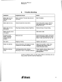
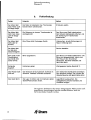
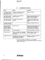
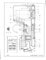
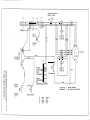
Planopol-3
Instruction Manual
Gebrauchsanweisung
Mode d’emploi
4 ~rue~
Serial No.:
Voltage:
*1991.09
Instruction Manual
Planopol-3
In technical enquiries and in orders for
spare parts, please state apparatus No.
and voltage (see cover).
All information and data in this
Instruction Manual were valid when it
was printed. The Struers policy being,
however, to make current improvements
of our products, we reserve ourselves the
right to modif~iour products without
notice. Besides, we ask you to note that
this Instruction Manual concerns
apparatus and all accessories.
Consequently, it may happen that the
Manual mentions equipment which is
not of relevance for your purpose at the
present time.
1.
Description
2.
Technical data
3.
Accessories
4.
Contents of packing case
5.
Installation
5.1
5.2
5.3
5.4
Setting up
Connection to mains
Connection to water
Mounting of Conversion Kit
6.
Operation
7.
Maintenance
8.
Trouble-shooting
9.
Spare parts (Appendix)
10. Illustrations (Appendix)
Struers A/S
Valhejs Allé 176
DK.2610 Rodovre/Copenhagen
Denmark
~ Telephone +45 31 70 80 90
~Fax +45 31 41 65 44
Telex 19625
if Struers
Instruction Manual
Planopol-3
1.
Description
Planopol-3 is a standard machine for lapping, wet grinding and
diamond and alumina polishing of metallographic, ceramic and
mineralogical specimens.
It has a circular turntable accepting grinding, lapping and/or
polishing discs of diameters up to 300 mm.
Supported by precision ball bearings, the turntable is driven via a
V-belt drive by a powerful two-speed electric motor, which ensures
smooth and noiseless running.
Motor and turntable are mounted on a steady steel frame also
supporting the cabinet. The latter is provided with a needle valve
for adjusting water admission, a flexible sprinicler tube and a spill
pan with drain.
On the control panel are arranged, to the right, three push buttons
with light indication for setting the speed (higb!low) and for stop.
The mains switch is easily accessible to the right on the front ofthe
cabinet.
if Struers
3
Instruction Manual
Planopol-3
2.
Voltage/frequency
Technical data
1-phase machines
115 V, 60 Hz
220 V, 50 Hz
3-phase machines
3 x 220 V, 50 Hz
3 x 380 V, 50 Hz
3x415V, 50Hz
3 x 440 V, 50 Hz
3 x 500 V, 50 Hz
3 x 220 V, 50 Hz
3 x 440 V, 60 Hz
3 x480 V, 60Hz
Motor output
1-phase
50 Hz 370, 220 W
60 Hz 450, 300 W
3-phase
50 Hz 550, 300 W
60 Hz 650, 370 W
Rotational speed
Standard
150, 300 rpm
Conversion Kit
75, 150 rpm
or
300, 600 rpm
or
600, 1200 rpm
Polishing/grinding disc
Max. 300 mm
Dirnensions
Height:
Width:
Depth:
Weight
53kg
Safety standard
IEC 204/ (VDE 0113)
EN 60204-1
4
if Struers
340 mm
462 mm
743 mm
Instruction Manual
Planopol-3
3.
Accessories
A complete range of different discs ofdiameters between 200 and
300 mm is available, including discs for grinding with grinding
paper, lapping on cast iron with a variety of surfaces, fine lapping
on plastics or special lapping discs, as well as polishing discs of PVC
and aluminum. In addition, a complete program ofconsumables are
available, such as polishing cloths, diamond paste or spray, SIC
paper or powder, alumina, etc. Please refer to separate leaflets.
Planopol-3 has been prepared for mounting ofPd.M-Force (fig. 2), a
motor-driven sample mover for simultaneous lapping and/or
polishing of1-9 specimens.
For automatic preparation offrom 3 to 12 specimens simultaneously
also Pedemax-2 (fig. 3) may be mounted on Planopol-3 (3-phase
model), thus making it possible to grind, lap and polish a number of
specimens at a time. Both PdM-Force and Pedemax-2 reduce the
preparation time and provide reproducible results. For details you
are referredto separate leaflets.
Conversion Kit
Planopol-3 is supplied as standard with 150/300 rpm. By mounting
of a Conversion Kit (codeword: PLATT) the following rotational
speeds may be obtained: 75/150, 300/600, and 600/1200 rpm.
if Struers
5
Instruction Manual
Planopol-3
Conversion Kit
6
4.
Contents of packing case
1
1
1
1
2
1
1
1
1
1
1
Planopol-3
Protection ring
Drain elbow pipe
Drain hose
Hose clips 20-32 mm
Hose connector
Union nut for hose connector
Sealing ring for hose connector
Hose clip 13 mm
Hexagon spanner 6 mm for turntable
Fuse0.5AT220V
1
1
1
1
1
1
1
1
1
3
V-belt pulley with two grooves (fig. 5.3)
Fitted bolt (fig. 5.2)
Washer (fig. 5.4)
Adjusting plate (fig. 5.1)
V-beltZ 17 (10x425 mm) (60 Hz)
V-belt Z 18 (10 x 450 mm) (50 Hz)
V-belt HY-T SPZ (10 x 1312 mm) (60 Hz)
Hexagon spanner (8 mm) for fitted bolt
Hexagon spanner (2.5 mm) for V-belt pulleys
Plastic plates stating the speeds 75, 600 and 1200 rpm
if Struers
Instruction Manual
Planopol-3
5.
Installation
5.1
Setting up
Planopol-3 is detached from the bottom ofthe packing case by
removing the four screws from below, after which Planopol-3 can be
placed on the bench.
5.2
Connection to mains
Before the apparatus is connected it must be checked that the
voltage which is indicated on the label ofthe machine, is in
accordance with the local voltage.
Mount a plug on the electric cable, connecting the leads as follows:
1-phase machine
Yellow/green lead to earth
Brown lead to phase
Blue lead to neutral
3-phase machine
Yellow/green lead to earth
Brown lead to phase
Black lead to phase
Black lead to phase
The turntable should rotate anti-clock wise. If this is not the case
after the connection, change the direction by changing over two of
the phase leads.
5.3
Connection to water
Connect the thin reinforced hose to a water outlet and fit the
13 mm hose clip. The accompanying hose connector with union nut
and sealing ring may, where not already provided, be mounted on
the water outlet (1/2” pipe thread, BS 2779: G 1/2).
If a recirculating cooling unit is used, connect the hose to the
discharge branch of the pump and fit a hose clip.
Lead the thick hose to the drain and be very careful to place it with
a steady downward slope to prevent the water from being
discharged too slowly which may cause overflow or blocking of the
water outlet. In order to avoid elbows on the hose, the enclosed
elbow pipe can be mounted on the tubing in an appropriate place.
if Struers
7
Instruction Manual
Planopol-3
5.4
Mounting of Conversion Kit
The rotary speed is changed by changing the transmission ratio of
motor and turntable. The V-belt pulley ofthe motor is provided
with two grooves of different diameters. In the standard version of
150/300 rpm the drive is effected directly from the small diameter
groove to the V-belt pulley ofthe turntable. If the motor V-belt
pulley is inverted so that the drive is established from the large
diameter groove, the speed ofthe turntable is doubled. Like the
motor V-belt pulley, the extra V-belt pulley has two grooves of
different diameters. By inserting this extra pulley as an inter
mediate wheel a speed either twice or half the one mentioned above
may be obtained, depending on which way the intermediate wheel
and the motor V-belt pulley are fitted.
The various combinations possible will appear from fig. 4, which
also shows which V-belts to use. Always make sure that the V-belt
pulleys are mounted in such a way that the belt pulls between two
grooves running in the same plane.
Change of rotational speed is done as follows (after disconnection of
power plug): Take out the 6 screws securing the rear section ofthe
cabinet and lift this section off. Remove the nuts securing the motor
bridge, after which the V-belt pulley may be mounted according to
fig. 5. Fit the V-belt pulley as shown in fig. 4, which indicates the
correct positioning ofthe motor V-belt pulley. The motor V-belt
pulley is fastened by means oftwo pointed screws in the bottom of
the V-belt grooves. When these screws are slackened, the V-belt
pulley can be pulled off~
For exchange of the long V-belt the turntable must be taken out.
This is done after removal ofthree screws at the top ofthe
turntable.
Position the belts as shown in fig. 4. First tighten the short V-belt
by means ofthe adjusting plate (fig. 5.1), then clamp the latter.
Remount the motor bridge and tighten the long belt by pushing the
motor rearward and clamp it into position.
It is important to ensure adequate belt tension since
undertensioning will cause the belt to slip on the pulleys, impairing
the drive transmitted to the turntable, whereas overtensioning
produces noise.
The long belt is correctly tensioned when a force of 5 N applied
halfway between the pulleys causes a bend of about 6 mm. When
applied to the short belt, the same force should produce a bend of
2-3 mm.
The push button plates indicating the new speeds are exchange by
first un screwing the metal ring round the buttons and then
pressing offthe green plastic plate. Fit the new indications and
assemble the buttons in reverse order. Finally, remount the rear
section ofthe cabinet.
8
if Struers
Instruction Manual
Planopol-3
6.
Operation
Planopol-3 is started by first operating the mains switch (fig. 1.1).
This actuates the red lamp in the uppermost ofthe three push
buttons at the right side (fig. 1.2). The button in the middle of the
three (fig. 1.3) starts the motor at low speed, whereas the lowest
button (fig. 1.4) switches to the higher speed. Activation ofthese
buttons causes the lamp built into each button to glow. The
machine is stopped by pressing the uppermost, red push button (fig.
1.2). The push buttons may be activated in any order. When
stopped by the mains switch or by a power failure, the motor does
not start on reconnection of power, but has to be started by
operation of the push buttons. This prevents unintentional motor
start during exchange of grinding/polishing disc.
In the case of prolonged overloading ofthe motor a built-in thermal
relay cuts out the motor, re-start being possible only after a period
ofcooling.
The grinding, lapping or polishing disc is mounted on the turntable
by inserting the three pins ofthe disc in the corresponding holes in
the turntable. Make sure that the contact surfaces are clean. The
water flow is controlled by a needle valve (fig. 1.5), and the
distribution of water is controlled by means of the flexible sprinkler
tube (fig. 1.6).
Below are stated the appropriate speeds for the various preparation
processes:
75 rpm
Lapping on cast iron discs and PAD-K pellon cloth. Diamond
polishing on Petrodisc and PA-W, PAN-W pellon cloth.
150 rpm
Diamond polishing (grinding/lapping on Petrodisc-M).
300 rpm
600 rpm
Wet grinding on grinding paper/wheel. Grinding on Petrodisc-M or
DP-Net.
Alumina polishing (automatic preparation).
1200 rpm
Alumina polishing (manual preparation).
The grinding paper may be af~.xedto a plane polishing disc by
means of Spray Adhesive, or it may be placed on a special disc
according to the Knuth-Rotor principle. By the latter method the
disc is filled with water while at rest, after which paper and
retaining ring are put on. Then the disc is made to rotate 300 rpm
while the entire surface of the grinding paper is pressed gently
against the disc with a specimen, or the like.
if Struers
9
Instruction Manual
Planopol-3
7.
Maintenance
Planopol-3 is designed and constructed for many years oftrouble
free running. It will not need much attention, as its bearings are
sealed and require no further lubrication. So maintenance will
generally be limited to cleaning the exterior ofthe machine, the
spill pan and the drain hose. Where the machine is used, for
instance, for alumina polishing or SiC lapping, the spill pan should
be cleaned sufficiently often to prevent drying out ofthe suspension
and thus any risk of blocking ofthe hose. In order to avoid erratic
disc movements, the contact surfaces between disc and turntable
should be kept clean.
Now and again the V-belt may need tightening, the transmission
being less efficient with inadequate belt tension. To tighten the belt,
remove the rear part ofthe cabinet, slacken the nuts securing the
motor plate and push plate and motor towards the rear until the
belt tension is correct. The belt is tightened correctly when a force
of 5 N, applied to the belt in the middle between the pulleys, causes
a bend of6 mm.
Exchange ofthe belt is effected by additionally removing the
turntable and loosening the nuts securing the motor plate so as to
slacken the belt, after which the belt can be taken off the turntable
pulley from above. Mounting ofthe new belt is done in reverse
order.
10
if Struers
Instruction Manual
Planopol-3
8.
Trouble-shooting
Indication
Explanation/cause
Action
Motor does not run.
Red light in stop
button.
Motor overload. Thermal relay has cut
out power.
Wait 5 minutes.
Motor does not run.
internal transformer fuse blown.
~
Disconnect power supply. Remove
rear cabinet section and replace
transformer fuse.
Motor does not run,
but buzzes.
One phase lacking (3-phase machine).
Check all fuses of local wiring.
Motor will only run at
one speed.
Call service man.
If other problems arise, or ifthe above failure
No light in push
button, otherwise
normal machine
function.
Bulb burnt out.
Disconnect power supply. Exchange
bulb by unscrewing ring round push
button. Insert new bulb and turn left.
Poor drive.
Slipping V-belt(s).
Tighten, see section 7.
Water not drained.
Hose pressed flat. Dirt trapped in hose.
Presence of air stops discharge.
Adjust hose position. Clean hose.
Discharge hose should have a
steady downward slope.
Machine produces
noise.
Grinding/polishing disc vibrates.
Bearings of motor or turntable defective,
Clean contact surfaces between disc
and turntable. Exchange
bearings/motor.
.
corrections do not
help, please call for a service technician.
if Struers
11
Gebrauchsanweisung
Planopol-3
Bei technische Fragen und Bestellung
von Ersatztei]en bitte App. Nr. und
Spannung angeben (siehe Vorderseite).
Alle AuskUnfte und Daten dieser
Gebraucbsanweisung waren bei der
Drucklegung geltend. Struers ist jedoch
bestrebt, laufend Verbesserungen des
Produkts vorzunehnien. Wir behalten
uns deshaib em Recht Zn fristlosen
Anderungen vor. Aul3erdem machen wir
Sie darauf aufmerksam, daB diese
Gebrauchsanweisung von GerMen und
dazu gehOrigem Zubehor handelt. Es ist
deshaib moglich, daB ZubehOr erwahnt
ist, das Zn demjetzigen Zeitpunkt fur
Sie nicht aktuell 1st.
1.
Beschreibung
2.
Technische Daten
3.
Zubehör
4.
Inhaft der Verpackung
5.
Installation
5.1
5.2
5.3
5.4
Aufstellung
Eiektrischer Anschlufl
Wasseranschluli
Montieren des Getriebeumbausatzes
6.
Bedienung
7.
Wartung
8.
Fehlerfindung
9.
Ersatzteile (Anhang)
10. Abbildungen (Anhang)
Struers A!S
Valhejs AVe 176
DK-2610 Rødovre/Gopenhagen
Denmark
e Telephone +45 31 70 80 90
~ Fax +45 31 41 6544
Telex 19625
if Struers
Gebrauchsanweisung
Planopol-3
1.
Beschreibung
Planopol-3 ist em Standardgerat zum Lappen, NaBschleifen und
Tonerde- mid Diamantpolieren von metallographischen,
mineralogischen mid keramischen Proben.
Es hat einen Drehteller, auf welchem die Schleif-, Lapp- und/oder
Polierscheiben mit Durchmessern bis zu 300 mm angebracht
werden.
Der Drehteller liegt auf Prazisionskugellagern mid wird durch
einen Keilriemen von einem starken Zweigeschwindigkeitsmotor
angetrieben, was einen gleichmai3igen mid gerauschlosen Lauf
gewahrleistet.
Der Motor mid der Drehtisch sind auf einem stabilen Stahlrahmen,
auf dem auch das Gehäuse befestigt 1st, montiert. Das Gehäuse ist
mit Nadelventil zu Regulierung von Wasserzufuhr, flexiblem
Spritzrohr, Ablaufschale mid AbfluB versehen.
Auf dem Bedienungspanel sind auf der rechten Seite drei
Druckknopfe mit Lichtanzeige zur Wall von niedriger, hoher
Geschwindigkeit mid Stopp angebracht.
Der Haupschalter sitzt bequem rechts an der Frontseite des
Gehäuses.
if Struers
3
Gebrauchsanweisung
Planopol-3
2.
Spannung/Frequenz
Technische Daten
1-phasiges Gerat
115 V, 60 Hz
220 V, 50 Hz
3-phasiges Gerät
3 x 220 V, 50 Hz
3 x 380 V, 50 Hz
3 x 415 V, 50 Hz
3 x 440 V, 50 Hz
3 x 500 V, 50 Hz
3 x 220 V, 60 Hz
3 x 440 V, 60 Hz
3 x 480 V, 60 Hz
Motor Output
1-phasig
50 Hz 370, 220W
60 Hz 450, 300W
3-phasig
50 Hz 550, 300 W
60 Hz 650, 370 W
Rotationsgeschwindigkeit
Standard
150/300 UIMin
Mit Getriebesatz
75/150 U/Min
IEC 204/ (VDE 0113)
oder
300/600 U/Mm
oder
600/1200 U/Mm
Scheibendurchmesser
Max. 300 mm
Abinessungen
Hohe:
Breite:
Tiefe:
Gewicht
53kg
340 mm
462 mm
743 mm
Sicherheitsstandard
EN 60204-1
4
if Struers
Gebrauchsanweisung
Planopol-3
3.
Zubehör
Es gibt eine Rethe verschiedener Scheiben mit Durchmessern von
200 bis 300 mm.
Planopol-3 1st zum Montieren von PdM-Force, einem
motorgetriebenen Proben führer zum gleichzeitigen Läppen
mid/oder Polieren von 1-9 Proben, vorbereitet (Fig. 2).
Zur gleichzeitigen automatischen Praparation von 3-12 Proben kann
auch Pedemax-2 (Fig. 3) auf Planopol-3 (3-phasig) montiert werden,
wodurch mehrere Proben gleichzeitig geschliffen, poliert mid
gelappt werden können. Sowohl PdM-Force als auch Pedemax-2
setzen die Praparationszeit herab mid ermoglichen reproduzierbare
Ergebnisse. Nähere Beschreibung, siehe Spezialprospekte.
Getriebesatz
Planopol-3 wird als Standard mit 150/300 U/Mm geliefert. Durch
das Montieren eines Getriebesatzes (Kennwort: PLATT) kOnnen
folgende Umdrehmigsgeschwindigkeiten erreicht werden: 75/150,
300/600 mid 600/1200 U/Mm.
if Struers
5
Gebrauchsanweisung
Planopol-3
Getri.ebesatz
6
4.
Inhalt der Verpackung
1
I
1
1
2
1
I
1
1
1
1
Planopol-3
Schutzring
Ablaufwinkelrohr
Ablaufschlauch
Schlauchklemmen 20-32 mm
Schlauchstutzen
Uberwurfmutter für Schlauchstutzen
Packung für Schlaucbstutzen
Schlauchldemine 13 mm
Imbul3schlUl3el 6 mm für Drehteller
Sicherung 0,5 AT 220 V
1
1
1
1
1
1
1
1
1
3
Keilriemenscheibe mit 2 Spuren (Fig. 5.3)
Pal3bolzen (Fig. 5.2)
Scheibe (Fig. 5.4)
Justierplatte (Fig. 5.1)
KeilriemenZl7(10x425mm)fur6OHz
Keilriemen Z 18 (10 x 450 mm) für 50 Hz
Keilriemen HY-T SPZ (10 x 1312) für 60 Hz
Imbui3schlili3el (8 mm) für den Pai3bolzen
Imbul3schliii3el (2,5 mm) für die Keilriemenscheiben
Kunststoffplatten mit Geschwindigkeitsanzeige 75, 600 und
1200 U/Mm
if Struers
Gebrauchsanweisung
Planopol-3
5.
Installation
5.1
Aufstellung
Planopol-3 wird von dem Boden der Verpackung gelost, indem die 4
Schrauben von miten entfernt werden, mid kann danach auf dem
Tisch angebracht werden.
5.2
Elektrischer AnschiuB
Bevor das Gerät angeschlossen wird, soil die Spannung die auf dem
Typenschild angegeben 1st kontrolliert werden, damit Sie mit der
am Ort befindlichen ubereinstitnmt.
Em Stecker wird auf das elektrische Kabel mit folgenden
Verbmndmigen montiert:
1-phasiges Gerat
Gelb/gruner Leiter mit Erde
Bramier Leiter mit Phase
Blauer Leiter mit Null
3-phasiges Gerät
Gelb/grüner Leiter zu Erde
Brauner Leiter mit Phase
Schwarzer Leiter mit Phase
Schwarzer Leiter mit Phase
Die richtige Umdrehungsrichtmig des Drehteilers ist gegen den
Ubrzeigersinn. Dreht der Teller nach Anschlul3 nicht in diese
Richtung, wird sie geandert, indem man zwei der Phasen im
Stecker umtauscht.
5.3
WasseranschluO
Der dünne verstärkte Schlauch wird an einen Wasserhahn
angeschlossen mid mit der 13 mm Schlauchklemmne festgespannt.
Der mitgelieferte Schlauchstutzen mit Packung mid
Uberwurfmutter kann, wenn dies nicht schon vorhanden 1st, auf
dem Wasserhahn montiert werden (½”
Rohrgewinde, BS 2779:
G½).
Wird elne Umlaulkiihlanlage verwendet, wird der Schlauch an den
Ausgangsstutzen der Pumpe angeschlossen mid mit einer
Schlauchklemme versehen.
Der dicke Schlauch wird zum Ablauf gefilirt, mid es 1st wichtig,
daB der Schlauch ein gleichmal3iges Gef~.llehat, da das Wasser
sonst zu langsam abläuft mid evtl. überläuft.
Um zu vermeiden, daB der Schlauch abknickt, kann das beigefugte
Winke]rohr an einer passenden Stelle montiert werden.
if Struers
7
Gebrauchsanweismig
Planopol-3
5.4
Montieren des Getriebeumbausatzes
Die Anderung der Umdrehmigsgeschwindigkeit wird durch die
Anderung der Ubersetzung zwischen Motor mid Drehteller erreicht.
Die Keilriemenscheibe auf dem Motor 1st mit zwei Spuren mit
verschiedenen Durchmessern versehen. Bel der
Standardausftthrung 150/300 U/Mm wird direkt von der Spur mit
dem kleinen Durchmesser zur Keiiriemenscheibe auf dem
Drehteller gezogen. Wird die Keilrieinenscheibe auf dem Motor
gedreht, so daB sie von der Spur mit dem groBen Durchmesser
zieht, wird die doppelte Geschwmndigkeit erreicht. Die lose
Keilriemenscheibe bat wie die Keilriemenscheibe auf dem Motor
zwei Spuren mit verschiedenen Durchmessern. Wird diese
Keilriemenscheibe als Zwischenrad eingescboben, erreicht man
abhangig davon, wie das Zwischenrad mid die Keilriemenscheibe
auf dem Motor gedreht wird, eine Geschwindigkeit, die doppel oder
haib so groB 1st wie die genannte.
Die verschiedenen Kombinationsmoglichkeiten, mid welcher
Keilrienien verwendet werden soil, gehen aus Fig. 4 hervor. Die
Keilriemenscheiben soilen immer so gewendet werden, daB der
Riemen zwischen zwei Spuren, die in der gleichen Ebene liegen,
zieht.
Das Wechseln der Umdrehungsgescbwindigkeit wird
folgendermaBen durchgefuhrt (den Netzstecker zuerst entfernen):
Die 6 Schrauben, die den hinteren Gehäuseteil halten, werden
entfernt, mid der Gehäuseteil wird abgehoben. Die Muttern, die die
Motorbrücke halten, werden entfemt, wodurch es moglich wird, die
Keilriemenscheibe nach Fig. 5 zu montieren. Die Keilriemenscheibe
wird wie auf Fig. 4 gezeigt gewendet, mid man kann dort auch
seben, wie die K.eilriemenscheibe des Motors gewendet wird. Die
Keilriemenscheilie auf dem Motor 1st mit 2 Pino]schrauben auf dem
Boden der Keilriemenspuren festgemacht. Werden diese Schrauben
gelost, kann die Kei.lriemenscheibe abgezogen werden. Soil der
lange Keiiriemen ausgetauscht werden, muI3 der Drehteller durch
Lösen der drei Schrauben entfernt werden.
Die Riemen werden angebracht, wie Fig. 4 zeigt. Erst wird der
kleine Riemen mit der Justierplatte (Fig. 5.1) gespannt, die danach
festgespannt wird. Danach wird die Motorenbrücke wieder
montiert, mid der groi3e Riemen wird durch Schieben der
Motorenbrucke nach hinten festgespannt. Es 1st wichtig, daB die
Riemenspannung ausreichend ist, da eine zu kleine
Riemenspannung den Riemen auf der Scheibe gleiten lal3t, wodurch
die Zugkraft verringert wird.
Eine zu groBe Riemenspannung flthrt da gegen Lärm mit sich. Die
Riemenspannung auf dem langen Riemen 1st richtig, wenn eine
Kraft von 5 N in der Mitte des Riemens eine Ausbietmig von ca.
6 mm mit sich filhrt. Bei derselben Kraft soil sich der kurze
Riemen 2-3 mm durchbiegen.
8
if Struers
Gebrauchsanweisung
Planopol-3
Die Druckknopfplatten mit der neuen Umdrehungszall werden
ausgetauscht, indem man zuerst den um den Druckknopf liegenden
Metaliring abschraubt, wonach die grüne Kunststoffplatte
abgeklemmt werden kann. Die neue Platte wird angebracht, mid
der Knopf wird in der entgegengesetzten Rethenfolge auf gesetzt.
Zum SchiuB kann der hintere Gehauseteil wieder montiert werden.
if Struers
9
Gebrauchsanweisung
Planopol-3
6.
Bedienung
Planopol-3 wird zunachst durch Anschalten des Hauptschalters
(Fig. 1.1) gestartet. Dadurcb leuchtet elne rote Lampe im oberen der
drei Druckknopfe auf der recbten Seite (Fig. 1.2) auf. Der mittlere
der drei Druckknopfe (Fig. 1.3) startet den Motor bel niedriger
Geschwindigkeit, mid der untere (Fig. L4) koppelt die bohe
Geschwindigkeit ein. Werden diese Knopfe gedruckt, leuchten die
im Knopf eingebauten Lampen. Das Gerät wird durch DrUcken des
oberen Knopfes gestoppt. Die Knopfe kdnnen in willkürlicher
Rethenfolge gedruckt werden. Nach Stopp des Motors durch den
Hauptschalter oder bei Stromausfail, startet der Motor thcht, wenn
der Strom wiederkommt. Er kann nur durcb Drücken der
Druckknopfe gestartet werden. Dies gewahrlelstet, daB der Motor
nicht startet, wenn man gerade die SchleiffPolierscheibe wechselt.
Wird der Motor langere Zeit überlastet, unterbricht ein eingebautes
Thermorelais den Motor, mid er kann erst nach kurzer Kühlzeit
wleder gestartet werden.
Schleif-, Lapp- mid Polierscheiben werden auf den Drehteiler
gesetzt, mid der Drehtisch wird gedrebt, bis die drei Beine in die
entsprechenden Lecher des Drehtellers passen. Die Auflageflache
soilte sauber sein.
Die Wasserzufulhr wird mit dem Nadelventil (Fig. 1.5) mid dem
flexiblen Spritzrohr (Fig. 1.6) geregelt.
75 U/Mm
tJnten sind die Geschwindigkeiten angefuhrt, die bei den
verschiedenen Praparationsvorgangen verwendet werden:
Lappen auf GuBeisenscbeibe oder Peilontuch PAD-K
Diamantpolieren auf Petrodisc oder Peilontuch PA-W oder PAN-W.
150 U/Mm
Diamantpolieren (SchleifenfLappen auf Petrodisc-M).
300 U/Mm
Nal3schleifen auf Schleifpapier/Stein. Schleifen auf Petrodisc-M oder
DP-Net.
600 U/Mm
Tonerdepolieren (automatische Praparation).
1200 U/Mm
Tonerdepolieren (manuelle Praparation).
Das Schleifpapier kann auf eine plane Polierscheibe mit Spray
Adhesive aufgeklebt werden oder auf eine besondere Scheibe nach
dem Knuth-Rotor Prinzip aufgelegt werden. Bei der letztgenaimten
Methode wird die Scheibe mit Wasser gefuilt, mid das Papier mid
der Halterring werden aufgelegt. Man lailt danach die Scheibe bei
300 U/Mm rotieren, gleichzeitig damit daB elne Probe leicht gegen
die Oberfläche des Papiers gedruckt wird.
10
if Struers
Gebrauchsanweismig
Planopol-3
7.
Wartung
Planopol-3 1st für langjalirigen wartungs freien Betrieb konstruiert,
da alle Lager gesehiossene fettgeschmierte Prazisionslager sind, die
keine weitere Schmierung benotigen. Die normale Wartmig besteht
deshalb in einer Reinigung des Gerätes auflen sowie einer
Reinigung der Ablaufschale mid des Ablaufschlauches. Arbeitet
man mit Tonerde oder SiC-Pulver-Suspension, soilte die
Ablaufschale so oft gereinigt werden, daB die Suspension nicht
eintrocknen kann, da der Ablaufschlauch dadurch verstopft. Die
äul3ere Reinigung des Gerätes soilte so trocken wie moglich
vorgenommen werden. Um zu vermeiden, daB die Scheibe schlagt,
soil die Kontaktflache zwischen dieser mid dem Drehteiler
saubergehalten werden.
Nach einigen Jahren soilte der Keilriemen nachgespannt werden,
cia sonst die Zugkraft geringer wird, wenn der Keilrlemen schlaf
wird. Dazu wird den hinteren Gehäuseteil entfernt, die Muttern, die
die Motorplatte halten, gelost mid diese nach hinten verschoben, bis
der Riemen strainm genug 1st. Der Riemen ist richtig gespannt,
wenn eine Kraft von 5 N zwiscben den Riemenscheiben elnen
Ausschlag von 6 mm gibt.
Ein Austauschen des Keilri.emens wird vorgenommen, indem man
ebenfalls den Drehteller entférnt, nachdem man die Muttern, die
die Motorenpiatte halten, gelost hat, mid der Keilriemen dadurch so
schlaf 1st, daB er von der Drehteilerriemenscheibe aus von oben
entfernt werden kann. Das Einsetzen des neuen Keilriemens
geschieht in umgekehrter Rethenfolge.
if Struers
11
Gebrauchsariweisung
Planopol-3
8.
Fehlerfindung
Fehler
Ursache
Aktion
Der Motor läuft
nicht. Rotes Lictit
im Stopp-Knopf.
Der Motor ist Uberlastet. Das Thermorelais
hat den Strom unterbrochen.
5 Minuten warten.
Der Motor lâutt
nicht. Kein rotes
Licht im StoppKnopf.
Die Sicherung im innereri Transformator 1st
durchgebrannt.
Den Strom zum Gerât unterbrechen.
Den hinteren Gehäuseteil entternen und
die Sicherung im Transformator
austauschen.
Der Motor läuft
nicht, aber er
brummt.
Eine Phase fehtt (3-phasiges Gerät).
Untersuchen, ob aHe Sicherungen im
Haus in Ordnung sind.
Der Motor Iãuft
nur bei elner
Geschwindigkeit.
Service besteilen.
Kein Licht in den
DruckknOpfen,
das Gerãt wirkt
sonst normal.
Birne ausgebrannt.
Den Strom zum Gerät unterbrechen. Die
Birne wird ausgewechselt, indem man
den Ring urn den Druckknopf
abschraubt, die Bime eincirUckt und
nach links dreht.
Schlechte
Zugkraft.
Keilriemen gleitet.
Wird gespannt (siehe Abschnitt 7).
Das Wasser läuft
nicht ab.
Der Schtauch 1st flach gedrUckt. Schmutz im
Schtauch. Luftblase verhindert austaufen.
Den Vertauf des Schlauches berichtigen.
Den Schlauch reinigen. Der Verlauf des
Ablaufschiauches soil gieichmâBig fallen.
Das Gerät Iärmt.
Die Lager im Motor oder im Drehteller defekt.
Schleif/Polierscheibe vibriert.
Lager/Motor austauschen. Die
Auflageflache zwischen Scheibe und
Drehtelier reinigen.
Bei anderen Problemen oder wenn obengenannte Feller nicht nach
angeflthrten Anweisungen behoben werden konnen, mul3 ein
Servicetechniker besteilt werden.
12
if Struers
Mode d’emploi
Planopol-3
Lors des demandes techniques et des
commandes de pièces de rechange,
priere d’indiquer no. d’appareil et la
tension du réseau (voir la premiere
page)
Tons les renseignements et données
compris dans ce Mode d’Emploi ëtaient
valables an moment de l’impression. La
politique de Struers étant d’améliorer
continuellement les produits, nous nous
réservons le droit de modifications sans
préavis. En outre, ii convient de noter
que ce Mode d’Emploi concerne
l’ensernble des appareils avec thus leurs
accessoires. II est done possible que des
accessoires sont mentionnés dont vous
n’avez pas l’utilisation a l’heure actuelle.
1.
Description
2.
Données techniques
3.
Accessoires
4.
Contenu de l’emballage
5.
Installation
5.1
5.2
5.3
5.4
Placement
6.
Operation
7.
Maintenance
8.
Localisation d’erreurs
9.
Pièces de rechange (Appendice)
Branchement electrique
Branchement d’eau
Montage des pièces de Ia trousse de conversion
10. Illustrations (Appendice)
Struers A/S
Valhajs AIlé 176
DK-2610 Redovre/Copenhagen
Denmark
e Telephone +45 31 70 80 90
e Fax +4531 41 6544
Telex 19625
if Struers
Mode d’emploi
Planopol-3
1.
Description
Planopol-3 eat mie machine standard pour le rodage, le prépolissage
sous eau ainsi que le polissage diamant et alumine d’échantiilons
metallographiques, céramiques et mineralogiques.
La machine comporte un touret rond sur lequel se placent les
disques de prepolissage, de rodage etlou de polissage de diamètre
maximum 300 mm.
Reposant sur des paliers de precision, le touret est alimenté par un
moteur pins sont a deux vitesses; ses courroies trapé zoldales
assurent une marche egale et silencieuse.
Le moteur et le touret sont montés sur un chassis d’acier stable sur
lequel est fixe le boltier; ce demier est muni d’un robinet d’eau,
buse flexible et receptacle a écoulement.
Sur le panneau opératoire se trouve, du côté droit, trois poussoirs a
indication lumineuse pour le choix de vitesse élevée et basse, ainsi
que d’arrêt.
L’interrupteur principal est facilement accessible a droite sur le
bord frontal du chassis.
4~Struers
3
Mode d’emploi
Planopol-3
2.
Tension /frequence
Données techniques
Machines moriophasées
115 V, 60 Hz
220 V, 50 Hz
Machines triphasés
3 x 220 V, 50 Hz
3 x 380 V, 50 Hz
3 x 415 V, 50 Hz
3 x 440 V, 50 Hz
3 x 500 V, 50 Hz
3 x 220 V, 60 Hz
3 x 440 V, 60 Hz
3 x 480 V, 60 Hz
Puissance du moteur
Monophasé
50 Hz 370, 220 W
60 Hz 450, 300 W
Triphasé
50 Hz 550, 300 W
60 Hz 650, 370 W
Vitesses de rotation
Standard
150/300 tlznin
Avec trousse de conversion
75/150 tlmin
oiL
300/600 tJmin
ou
600/1200 timin
Diarnètre du disque
Max. 300 mm
Dimensions
Hauteur:
340 mm
Largeur:
462 mm
Profondeur: 743 mm
Poids
53kg
Standard de sécurité
IEC 204/ (VDE 0113)
EN 60204-1
4
if Struers
Mode d’emploi
Planopol-3
3.
Accessoires
Pour Planopol-3 il existe une série complete de disques diamètres
200 mm a 300 mm, prévus au prepolissage avec papier abrasif collé,
ou appliqué selon le système Knuth-Rotor, au rodage sur fonte avec
surfaces de nature différente, au rodage fin sur plastique, ou
disques de rodage spéclaux, et en~findisque de polissage en PVC ou
aluminium. En outre un programme complet de produits
consommables, tels que draps de polissage, pâte/spray diamant,
papier/poudre SiC, oxyde d’aluminium, etc. Voir les notices
spéciales.
Planopol-3 est preparee pour montage de PdM-Force (fig. 2), un
porte-echantifions actlonné par moteur pour rodage etlou polissage
simultané de 1-9 échantillons.
Pour la preparation automatique d’un nombre d’échantillons de 3 a
12 simultanément, egalement Pedemax-2 (fig. 3) pent se monter sur
Planopol-3 (modèle Triphase), permettant de prepolir, de roder et de
polir plusieurs échantiilons en même temps. PdM-Force, aussi bien
que Pedemax-2 réduisent la durée de preparation et assurent des
résultats reproductibles. Pour descriptions plus dé taiilées, voir nos
prospectus spéciaux.
Trousse de conversion
Planopol-3 est livrée comme modèle standard pour mie vitesse de
rotation de 150/300 tlmin. Au moyen d’une trousse de conversion
(mot de code: PLATT) les vitesses de rotation suivantes peuvent
être obtenues: 75/150, 300/600 et 600/1200 tlmin.
if Struers
5
Mode d’emploi
Planopol-3
4.
Contenu de Ia caisse de transport
1
1
1
1
2
Planopol-3
Anneau de protection
Tuyau d’écoulement
Tubulure d’equerre pour l’écoulement
Coffiers de serrage 20-32 mm
Raccord d’extrémite
Ecrou tendeur pour raccord
Garniture pour raccord
Collier de serrage 13 mm
Clef a six pans 6 mm pour touret
Fusible
1
1
1
1
1
1
Trousse de conversion
1
1
1
1
1
1
1
1
1
3
6
Poulie pour courroie trapezoIdale a deux gorges (fig. 5.3)
Boulon ajusté (fig. 5.2)
Disque (fig. 5.4)
Plaque d’ajustage (fig. 5.1)
Courroie trapezoldale Z 17 (10 x 425 mm) (60 Hz)
Courroie trapezoldale Z 18 (10 x 450 mm) (50 Hz)
Courroie trapezoldale HY-T SPZ (10 x 1312 mm) (60 Hz)
Clef a six pans (8 mm) pour le boulon ajusté
Clef a six pans (2,5 mm) pour les poulies a courroie
Plaques de plastique indiquant les vitesses 75, 600 et
1200 tIm
if Struers
Mode d’emploi
Planopol-3
5.
Installation
5.1
Placement
Planopol-3 est enlevé du fond de la caisse de transport en retirant
par le bas les quatre vis, après quoi Planopol-3 pent être place sur
la table.
5.2
Branchement electrique
Avant le branchement de l’appareil, contrôler que la tension
indiquee sur la plaque de l’appareil correspond a la tension locale.
Une fiche est montée sur le cable électrique avec lea connexions
suivantes:
Machine rnonophasée
Conducteur jamie/vert a la terre
Conducteur brun a la phase
Conducteur bleu a zero.
Machine triphasée
Conducteur jaune/vert a la terre
Conducteur brim a la phase
Conducteur noir a la phase
Conducteur noir a la phase
Le sens de rotation correct du touret eat a l’inverse des aiguilles
d’mie montre. Si après le branchement la rotation du touret ne se
fait pas dans ce sens, ii faut changer le sens de rotation en
changeant deux phases dams la prise.
5.3
Branchement d’eau
Le mince tuyau renforcé eat branché au robinet d’eau et muni du
collier de serrage 13 mm. Le raccord avec garniture et l’écrou
tendeur en annexe pent se monter au robinet (an cas qu’il ne soit
pas déjà livré) (filet ½”
BS 2779: G ½).
Si wi système d’arrosage recyclant est utilisé, il faut connecter le
tuyau an raccord de decharge sur la pompe et le munir de colliers
de serrage.
Le tuyau épais est conduit a l’écoulement, et il importe que le tuyau
soit place avec une chute egale, autrement l’eau coule trop
lentement ce qui peut résulter a une perte d’eau ou l’obturation du
tuyau d’écoulement.
Afin d’éviter des coudes sur le tuyau, le tuyau coudé livré avec
l’equipement pent être monte dans un endroit approprié.
if Struers
7
Mode d’emploi
Planopol-3
5.4
Montage des pièces de Ia trousse de conversion
Une modification de la vitesse de rotation eat obtenue en changeant
le rapport de transmission entre le moteur et le touret. La poulie a
courroie sur le moteur eat munie de deux gorges de diamètres
différents. Dans la version standard 150/300 tlinin la traction se fait
directement de la gorge de petit diamètre a la poulie au touret. Si la
courroie sur le moteur eat tournée et Ia traction a lien de la gorge
au grand diaxnètre, la vitesse de rotation du touret est doublée La
poulie détachée a deux gorges de diamètres différents, comme la
poulie a courroie sur le moteur. En intercalant cette poulie a
courroie comme rone intermédiaire, l’on obtient, ou bien une vitesse
double, ou bien la vitesse moitié de celle mentionnée, dependant de
quelle manière sont tournées Ia rone intermédiaire et Ia poulie sur
le moteur.
Lea diveraes possibilites de combinaison s’ensuivent de la fig. 4 qui
indique egalexnent lea courroies a employer. Il faut toujours se
rappeler de tourner lea poulies a courroie afin que la courroie tire
entre deux gorges an mème niveau.
Le changement de vitease de rotation se fait comme suit (sortir
d’abord la fiche de la priae du réseau):
Enlever les 6 vis retenant l’unité du boltier a l’arrière et enlever
l’unité du boItier. Enlever lea écroua retenant le pont du moteur,
après quoi il eat possible de monter Ia poulie a courroie suivant fig.
5. La poulie a courroie eat orientée suivant fig. 4, d’oit l’on voit
également comment doit être tournée la poulie a courroie sur le
moteur. La poulie sur le moteur eat flxée a l’aide de deux vis
pointues au fond des gorges des courroies trapézo’idales. Quand ces
via sont deaserrées, hi pouiie pent ètre enlevée.
Pour remplacer Ia grande courroie, II faut enlever le touret. Ceci
peut être fait après enlèvement des trois vis au sommet du touret.
Les courroies doivent être placees comine indique dans fig. 4.
D’abord tendre la petite courroie a l’aide de hi plaque d’ajnstage
(fig. 5.1) qui est en suite flxée par serrage. Par hi suite le pont de
moteur eat monte a nouveau, et l’on pent tendre Ia grande courroie
en poussant le pont du moteur en arrière et le serrer.
Ii eat important de tendre les courroies su~aamment,car mie
tension trop faible a pour résultat que la courroie glisse sur les
poulies, réduisant la force de traction du touret. D’autre part, une
tension trop forte produit du bruit.
La tension est correcte sur la grande courroie quand une traction de
5 N au milieu des poulies résultat a une flèche de 6 mm environ.
Avec la méme force Ia courroie courte doit avoir une flèche de
2-3 mm.
8
if Struers
Mode d’emploi
Planopol-3
Remplacer lea plaques aux poussoirs avec lea nouveaux chiffres de
rotation en déviasant d’abord l’anneau de metal an tour des
pousaoirs et enlevant ensuite la plaque verte de plastique en Ia
coinçant. Maintenant placer lea nouvelles indications et assembler
les boutons poussoir inveraement. Finalement, remonter l’unité du
boltier a l’arrière.
if Struers
9
Mode d’emploi
Planopol-3
6.
Operation
Planopol-3 eat mis en marche a l’aide dii commntateur principal
(fig. 1.?). Par la suite la lampe rouge dn poussoir supérieur des trois
boutons du cSté droit (fig. 1.2) s’allume. Le poussoir au centre (fig.
1.3) démarre le moteur a basse vitesse, alors que le poussoir
inférieur (fig. 1.4) embraie la grande vitesse. Quand ces boutons
sont actionnés, la lampe incorporée dana le bouton s’allume. La
machine s’arrête par une pousaée au bonton supérieur. Les
poussoirs peuvent être actionnés par ordre arbitraire. Si le moteur
eat arrêté a l’aide du commutateur principal, on a cause de
defaillance du courant, le moteur ne démarre pas quand le circuit
est fermé a nouveau, mais doit être remis en marche par pression
des pousaoirs.
Ceci pour prévenir un démarrage non-intentionné dnrant
remplacement de la menle ou du diaque de polissage.
Si le moteur a éte exposé a mi surcharge prolongee, un relais
thermique arrête le moteur qui ne pourra être redémarré qu’après
être refroidi.
Le disque de prépolissage, de rodage on de polisaage eat monte sur
le touret en le tournant jusqu’a ce que lea trois goujons peuvent
entrer dana lea trous correspondants dams le touret. Veiller sur ce
que hi surface de contact soit bien propre. L’alimentation en eau se
règle par un robinet (fig. 1.5) et la distribution d’eau se regle par le
gicleur souple (fig. 1.6).
75 t/min
Dans le suivant sont indiquees lea vitesses qui s’appliquent aux
procedés di.fférents:
Rodage aux disques de fer de fonte et drap Pellon PAD-K Polissage
diamanté an Petrodiac et aux draps Felon PA-W et PAN-W.
150 tlmin
Poliasage diamanté (prepolissage/rodage aur Petrodisc-M).
300 t/min
Prépolissage sons eau a papier abrasWmeule.
600 t/min
Polissage d’alumine (preparation automatique).
1200 t/min
Polissage d’alumine (preparation manuelle).
Le papier abrasif pent être collé sur un disque de polissage plat a
l’aide dii ‘Spray adhésifs’ on il pent être mis aur un disque special
d’après le principe Knuth-Rotor. Selon cette dernière méthode, le
disque irmnobile est rempli d’eau, après quol le papier et l’aimeau
de retenue sont appliqués. Par Ia suite le disque eat mis en rotation
a 300 tours/mm an minimum en méme temps qu’on appule
legèrement, avec un échantillon on aemblable, en pressant toute la
surface dii papier contre le disque.
10
if Struers
Mode d’emploi
Planopol-3
7.
Maintenance
Planopol-3 eat construite pour opérer pendant de nombrenses
années sans interventions d’importance, grace aux paliers de
precision herinetiques et lubriflés n’exigeant pas de graissage
ultérieur. L’entretien normal consiste donc seulement en nettoyage
a l’extérieur de la machine, ainai que de rinçage dn receptacle et du
tuyau d’écoulement. Si on travaille avec un polissage a alumine, par
exemple, ou avec un rodage SiC, il fant nettoyer le receptacle aasez
souvent af.in que la suspension n’ait pas le temps de aécher et
boucher le tuyau d’écoulement. Le nettoyage de l’extérieur dolt être
fait avec un chiffon tordu, aussi sec que possible. Afin d’éviter que
le disque gondole, la surface de contact entre le disque et le touret
doit être tenue propre.
Au bout de quelques années de service, il pent devenir nécessaire de
tendre la courroie car la tension ae reduit Si la courroie n’est pas
aasez tendue. A cot effet enlever l’unité du coifret an-dessus du
panneau opératoire en desaerrant lea écrous retenant la plaque du
moteur et en poussant la plaque et le moteur en arrière jusqu’a ce
que hi courroie soit suffisamment tendue. Lea courroies sont
correctement serrées qnand tine force de 5 N chargée au milieu
entre lea poulies résulte a mi écart de 6 mm.
Pour remplacer Ia courroie II Taut également enlever le touret, après
avoir des serré les écrous retenant la plaque moteur pour que la
courroie soit de tendue. On pent enlever celle-ci de Ia poulie du
touret, d’en haut.
Montage d’mie nouvelle courroie se fait en sens inverse.
if Struers
11
Mode d’emploi
Planopol-3
8.
Localisation d’erreurs
Erreur
Cause
CorrectIon
Le moteur ne marche
pas. Lumière rouge
dans le bouton d’arrêt.
Le moteur est surcharge. Le relais
thermique a coupé le courant.
Attendez 5 minutes.
Le moteur ne marche
pas. Pas de lurnière
dans le bouton d’arrêt.
Le fusible sur Le transtormateur
intérieur est fonclu.
Couper le courant. Enlever runité du
boltier en arrière et remplacer le
fusible sur le transformateur.
Le moteur ne marche
pas, mais bourdonne.
Une phase manque (appareil
Triphasé).
Verifier Si tous les fusibles dans
t’installation de Ia maison soient en
ordre.
Le moteur ne marche
qu’à une seule vitesse.
Appelez un technicien de service.
Pas de lumière dans
le bouton poussoir,
autrement l’appareil
marche normalement.
La poire a sauté.
Couper le courant. Changer Ia poire
en dévissant t’anneau autour du
bouton poussoir en enfonçant Ia
poire et toumer celle-ci a gauche.
Mauvaise traction.
Le courroies glissent.
Doivent être tendues. Voir section 7.
L’eau ne sort pas.
Le tuyau est aplati. II y a cf’impuretés
dans le tuyau. Une boule d’air bouche
l’écoulement.
Rectifier le tuyau. It faut qu’il y air
une chute égate du tuyau.
L’appareil faR du bruit.
Les paliers dans le moteur ou le touret
sont défectueux. Les disques de
prépolissage/potissage vibrent.
Nettoyer Ia surface de contact entre
le disque et le touret.
Si d’autres problemes se produisent, ou si lea défauts
aus-mentionnés ne peuvent être supprimés a l’aide des indications,
appeler mi technicien.
12
if Struers
Instruction ManuallGebrauchsanweisungfMode d’emploi
Planopol-3
9.
Spare parts/Ersatzteile/Pièces de rechange
Fig.I
Description
Pos.
Bottom frame
6.1
Bottom frame
6.2
Rubber knob
6.3
Plate for water inlet
6.4
Rubber bush
6.5
Rubber disc
6.6
Aluminium disc
dia. 8.5/27 x 2.5 mm
6.7
Motor bridge
6.8
Spacer
6.9
Motor plate
6.10 Turntable support bridge
6.11 Base plate for column, left
6.12 Base plate for column, right
Casing
6.13 Rear part
6.14 Front part
Front plate text foil
6.16 Spifi pan incl. PVC tube
6.17 Splash ring
Cover
6.28 Cover plate
Driving system
6.19 Turntable
6.20 Hub
6.21 Grooved pulley
6.22 Ball bearing SKF 6205-2 Z
6.23 Spacing bush
6.24 Shaft
6.66 Seeger ring U25 x 1.2 mm, 2 pca.
6.64 Thrust collar for ball bearing
dia. 41.6 x 25.2 mm, 2 pea.
6.25 V-belt HY-T SPZ 1237
6.26 Motor pulley 50 Hz
6.27 Motor pulley 60 Hz
if Struers
Spare part No.
414 MP
414 MP
401 Ml?
414 MP
414 MP
414 MP
1
2
64
4
5
6
414MP7
414 MP 8
414 MP 9
414 NP 10
414 NP 11
414 MP 12
414 MP 13
414 NP 14
14140089
414 NP 16
414 MP 17
414 MP 18
414 MP 28
266
414
414
414
414
414
414
414
MP
NP
NP
NP
NP
MP
MP
MP
52
20
21
22
23
24
66
64
414 MP 25
414 MP 26
414 NP 27
1
Instruction Manual!Gebrauchsanweisung/Mode d’emploi
Planopol-3
Fig.f
Pos.
Description
Electricparts
6.29 Motor 3 x 220 V/50 Hz
Motor 3 x 380 V/SO Hz
+ 3 x 440 V, 60 Hz
Motor 3 x 415 V, 50 Hz
Motor 3 x 440 V, 50 Hz
Motor 3 x 500 V, 50 Hz
Motor 3 x 220 V, 60 Hz
Motor 3 x 480 V, 60 Hz
Motor 1 x 115 V, 60 Hz
Capacitor 115 V, 60 Hz
Motor 1 x 220 V, 50 Hz
Capacitor 220 V, 50 Hz
6.38 Main switch
6.39 Contactor 50 Hz
Contactor 60 Hz
6.41 Thermorelay 3 x 220 V, 50 Hz
Thermorelay 3 x 220 V, 60 Hz
Thermorelay 3 x 380 V, 50 Hz
Thermorelay 3 x 415 V, 50 Hz
Thermorelay 3 x 440 V, 60 Hz
Thermorelay 3 x 500, 550 V, 50 Hz
Thermorelay 1 x 220 V, 50 Hz
Thermorelay 1 x 115 V, 60 Hz
6.49 Transformer
6.50 Fnseholder
6.51 Pushbutton without change-over
switch, 0-red
Pushbutton without change-over
switch, 150-green
Pushbutton without change-over
switch, 300-green
6.54 Change-over switch
6.55 Bulb 24 V, 0.08 A
Fuse 0.5 AT
6.57 Screwed connection for cable PG 11
Water inlet outlet
6.63 Reinforced tube 5/16” x 2 m with ¾nipple
6.58 Needle valve for water
6.59 Reinforced tube 3/8” x 300 mm
6.60 Adjustable metal tube 3/8” x 320 mm
Outlet tube dia. 25 x 350 mm
‘J.v.L
6.62 Outlet tube branch
~
2
Spare part No.
414 NP 29
414 NP 30
414 NP 31
3940238
414 NP 32
414 Ml? 33
3620058
414 NP 34
414 NP 35
414 NP 36
414 NP 35
414 NP 38
414 NP 39
414 NP 40
414 NP 41
414 NP 42
414 NP 43
414 NP 43
414 NP 43
414 NP 46
414 NP 42
414 NP 48
414 NP 49
414 NP 50
414 NP 51
414 NP 52
414 Ml? 53
414
414
414
414
NP
NP
NP
NP
54
55
56
57
414 NP
414 NP
414 NP
414 NP
414 NP
414 NP
63
58
59
60
61
62
-
if Struers
Instruction ManuallGebrauchsanweisung/Mode d’emploi
Planopol-3
10. Illustrations/Abbildungen/Ulustrations
if Struers
Fig. 1
1
Fig.
2
Fig. 3
Struers Planopol-3 87,01
75 /
150
300 / 600
150 / 300
600/ 1200
Struers Planopol-3
2,86
362-M-102R
Fig. 5
Struers Planopol-3
.
2.86
-
362-M-1O1R
Fig. 6
Struers Planopol-.3 ‘414-.M.-5R
4;~w~rrgs
1’ exept mocked
A~c ~Qbe~
1
nu~r~ch$de rp~tma~ke
bk
br,
bi
ye
gn
•
•
•
•
•
block
brown
blue
yetlow
gren
schworz
broun
blau
geib
• grun
•
•
•
•
Struers Planopol—3 4140063D 05.91
Wiring diagramfLeitungsschaltplan
3 x 220-550 V
‘
.
Cl
4,?cMF
2SuF
1
•
except marked
A:(e k~be!’~1
At! wuIngs
•
nut n,cht die m!t rnørk~
b.
~,
• *~0i,t
0*
0
•0,c
‘
SChOfl
•
•
pCD
I
U
115V 60k:
220V 50Hz
r,u
Struers Planopol-.3 ‘4140064B ‘04.89
Wiring diagram 1
115/220 V
Leitungschaltplan 1
115/220 V
-s’-.’
i—’
Phase Capasitor
Phase Kondensotor
Cl
Thermal Protection
Motor-Schutz
£50 I 300
370 / 250
~:
(1~
—.
‘4
- —~
C
‘4 Ui
o
N
t’ )
0
-~
0
0
Gehäuse
unten
0~’
00.11
o
x
N
All wirings I
Alto kabetn 1
I
0
00
00
bk
bn
bI
ye
gn
•
•
•
•
•
black
schwarz
brown • braun
blue
~ blau
yellow • gelb
green • grUn
Thermal Prot. Sethng
Motor Schutz Einstellung
Phase Capas~tor
Phase Kondensator
~
229/go
Fl
6.2A
2.8A
Cl
4.2SuF
25uF
,
.
except marked
nur nicht die mit marke
w
w
Thermal Protection
Motor- Schutz
4.1
6,l
bkfl
bk
bn
II
r~ibk fl
bk
bk
bn
4.l~
Si
6
~
fl
I
II
5
L..4~1
2~’
,bn
2.....J~1
ku
‘feign
v~I~n
Fl
bk
II
I
2 rfl
2
1
bkl
4rIi__
hi,
hiol
bn
bkb
U
U
Front
w
Cabinet
j
Speed.
Fr
r
On
r
r
Gehäus~
e
vorne
WIV1
6— -—c
11
Baseplote
Fundament
__________________
yelgn__1’
yelgn
Ti
x
‘-~
l\)r
Control Volta
vo~
Safety
Primary
geLS
Transformer
-i
C
(it
~1
Ui
Primär
Hilfstromkreis—
lout
‘.1,—, —
‘•.n p.i
p~
OOQ ~
~10
Bottom
<p)-
3o0
La
00
0~ ’r,
D
~
Frontptate~
Frame
Pot.
Gehduse
unten
Polierscheibe
•
‘
•
black
brown
blue
yellow
gren
•
K2
7.075
I
Frontptatte
4
•
0.55-0.3 kW
-,
[4i~hj
Sicherheitstransformator
bk
bn
bi
ye
gn
hioFt
.bkk.
4—ff--3
2-fi~l
l4~ft 13
54
53
Ul
schwarz
braun
blau
goib
grün
ye/gn
Alt wirings
Allekabel,n
1, except marked
1 • nur nicht die mit marke
IStop]
Thermal Protection.
Internal
Fuse.
Interne
Sicherung.
Secundary
Control Voltage
Safety
Transformer.
Sekundär
Hilfstrom-
0—
<
kreislauf
Transformer.
~3
o2. OQ
0)
U)
0
~V
0
N C Q.
(fl g
n0 i
:3- 0)
—
‘4
1~
0
0
—
a’
:3
0
00
00
rd
red
rot