1
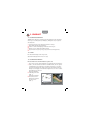
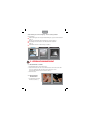
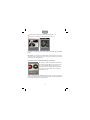
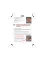
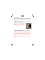
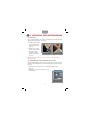
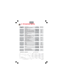
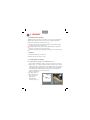
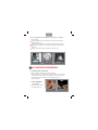
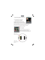
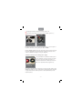
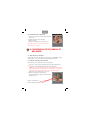
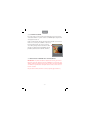
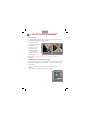
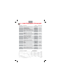
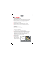
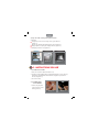
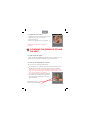
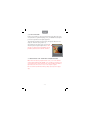
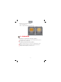
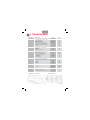
Gebrauchsanleitung
Mode d‘emploi
Instructions
INHALTSVERZEICHNIS
1. PRODUKT
1.1. Produktbeschreibung ............................................................................ Seite 04
1.2. Patent ............................................................................................................... Seite 04
1.3. Produktbestandteile................................................................................ Seite 04
2. GEBRAUCHSANWEISUNG
2.1. Einsetzen des Systems ........................................................................... Seite 05
2.2. Anschliessen an den Helm.................................................................. Seite 05
2.3. Anpassung der Hörer des Helms .................................................... Seite 06
2.4. Entfernen des Systems .......................................................................... Seite 08
3. KONTROLLE DES JRENUM-FILTERSYSTEMS UND DER
AUGLEICHSBOHRUNG
3.1. Zweck der Kontrolle ............................................................................... Seite 08
3.2. Aufgabe des Filters und der Ausgleichbohrung ................... Seite 08
3.3. Vorgehensweise ......................................................................................... Seite 09
3.4. Erforderliche Vorsichtsmassnahmen ............................................ Seite 09
4. REINIGUNG UND AUFBEWAHRUNG
4.1. Reinigung ...................................................................................................... Seite 10
4.2. Aufbewahrung und Trocknung des Systems ......................... Seite 10
5. GEWÄHRLEISTUNG .................................................................................... Seite 11
6. TECHNISCHE DATEN ................................................................................. Seite 12
SOMMAIRE
1. PRODUIT
1.1. Description du produit ......................................................................... page 13
1.2. Brevet ............................................................................................................... page 13
1.3. Composants du produit ...................................................................... page 13
2. NOTICE D'UTILISATION
2.1. Insertion de l‘oreillette.......................................................................... page 14
2.2. Raccordement au casque ................................................................... page 14
2.3. Ajustment des écouteurs..................................................................... page 15
2.4. Extraction de l’oreillette ...................................................................... page 17
– 02 –
3. CONTRÔLE DU FILTRE JRENUM ET DE L'ÉVENT
3.1. Objectif de ce contrôle ....................................................................... page 17
3.2. Rôle de ce filtre et de cet évent ...................................................... page 17
3.3. Comment procéder .............................................................................. page 18
3.4. Précautions à prendre avec le filtre Jrenum ............................ page 18
4. NETTOYAGE ET RANGEMENT
4.1. Nettoyage de l‘oreillette .................................................................... page 19
4.2. Rangement et séchage du système ............................................. page 19
5. GARANTIE ......................................................................................................... page 20
6. CARACTÉRISTIQUES TECHNIQUES ................................................ page 21
CONTENTS
1. PRODUCT
1.1. Product Description ............................................................................... page 22
1.2. Patent .............................................................................................................. page 22
1.3. Product Components ............................................................................ page 22
2. INSTRUCTIONS FOR USE
2.1. Fitting the System ................................................................................... page 23
2.2. Connections to the Helmet ............................................................... page 23
2.3. Adjustment to the Helmet ................................................................. page 24
2.4. Removing the System ........................................................................... page 26
3. CHECKING THE JRENUM FILTER AND THE VENT
3.1. Purpose of this check ............................................................................ page 26
3.2. Role of the filter and of the vent.................................................... page 26
3.3. How to proceed ........................................................................................ page 27
3.4. Precautions to be taken with the Jrenum filter .................... page 27
4. CLEANING AND STORAGE
4.1. Cleaning......................................................................................................... page 28
4.2. Storage and Drying of the System ............................................... page 28
5. GUARANTEE .................................................................................................... page 29
6. TECHNICAL DATA ....................................................................................... page 30
– 03 –
Deutsch
1. PRODUKT
1.1. PRODUKTBESCHREIBUNG
OMARA wurde für Piloten und fliegendes Besatzungspersonal entwickelt,
um bei grossen Lärmquellen (in Militärjets, Helikoptern usw.) folgendes
sicherzustellen:
Vernehmen und Verstehen akustischer Alarme im Cockpit.
Klare Wahrnehmung aller Nachrichten.
Schutz vor Lärm und langfristiger Erhalt des Hörvermögens.
Abbau von Stress durch klare Wahrnehmung.
Ergonomisches Design in puncto geringes Gewicht und Tragekomfort.
1.2. PATENT
Eine Patentanmeldung wurde eingereicht.
(Patentanmeldungsnummer 2005 11 38/5)
1.3. PRODUKTBESTANDTEILE
Die Bestandteile des Kommunikationssystems sind:
Zwei einzelne weiche (Silikon-)Ohrstücke mit eingebauten Filtern und Hörern
(Abb. 1): Die Filter schützen das Ohr vor schädlichem Lärm, ohne die Sprachverständlichkeit zu beeinträchtigen. Zusätzlich ermöglichen sie den barometrischen Ausgleich für die Kompensierung des Höheneffekts und die Belüftung des Gehörganges für maximalen Tragekomfort. Der Hörer verstärkt
die Meldungen des Intercom.
Kabel und Anschlussverbindung zum Helm
(Abb. 1).
Eingebauter Helmsatz
mit Connector und
Kabeln zum Anschluss
an das Intercom
(Abb. 2).
Abbildung 1
Abbildung 2
– 04 –
Deutsch
Aufbewahrungsbox mit Reinigungs- und Trocknungsartikeln
Bestehend aus:
Aufbewahrungsbox zur richtigen Aufbewahrung des Systems nach Gebrauch
(Abb. 3).
OtoEase zur Reinigung und Desinfektion des Systems (Abb. 4).
Trockenkapseln zum Trocknen der Ohrstücke nach Gebrauch
(Abb. 4).
Schutzhaube für den mobilen Transport (Abb. 5).
Abbildung 3
Abbildung 4
Abbildung 5
2. GEBRAUCHSANWEISUNG
2.1. EINSETZEN DES SYSTEMS
1. Anschlusskabel hinter den Nacken legen.
2. Rechte Ohrmuschel mit der rechten Hand erfassen und in das rechte Ohr
einsetzen, dabei das Ohr nach hinten und nach unten ziehen.
Am linken Ohr gleichermassen verfahren (Abb. 6).
3. Helm aufsetzen.
2.2. ANSCHLIESSEN
AN DEN HELM
1. Steckverbinder am Helm
anschliessen (Abb. 7).
Abbildung 6
– 05 –
Abbildung 7
Deutsch
2. Kabel mit Klettband am
Helm befestigen (Abb. 8).
2.3. ANPASSUNG DER HÖRER
DES HELMS HGU-55/OMARA
Der Durchmesser der OMARA-Koaxialkabel wurde
Abbildung 8
für eine hohe mechanische Festigkeit und eine
optimale Übertragungsqualität ausgelegt. Um Optimierung des Tragekomforts zu erzielen, ist daher bei der Positionierung der Hörer im Jet-Helm
besondere Vorsicht geboten.
Die Position der Hörer kann auf drei Arten angepasst werden
Höhenanpassung
Seitenanpassung
Winkelposition
Abbildung 9
Die Hörer sind mittels Klettverschluss befestigt, was
eine Höhenanpassung erlaubt.
Die seitliche Anpassung kann mithilfe von Einlagen
erfolgen (Abb. 9).
Einlage für
Winkelanpassung
Einlage für seitliche
Anpassung (Abb. 9)
– 06 –
Deutsch
Zuschneiden der Einlage für die Winkelanpassung (Abb. 10).
Positionieren der Einlage zur Winkelanpassung (Abb. 11).
Abbildung 10
Abbildung 11
Ist der Hörer korrekt positioniert, ist am unteren Ende Platz für das OMARA
Kabel.
Da OMARA einen angemessenen Gehörschutz sicherstellt, müssen die Hörer
des Helms nicht zu stark auf die Ohren gepresst werden. Die Verwendung
von Einlagen ist nicht zwingend.
Auswahl der Hörer-Schaumstoffdichtung für den Helm
Der zurzeit im Schweizer Flugdienst zum Einsatz
kommende Jet-Helm HGU-55 ist mit zwei Sorten
von Schaumstoffdichtungen auf den Hörern
ausgestattet. Eine ist völlig gleichförmig, während
die andere am unteren Ende einen Vorsprung
aufweist (Abb. 12).
Abbildung 12
Letztere dürfen nicht mit OMARA benutzt werden, da sich der Vorsprung
genau an der Durchgangsstelle des Kabels befindet, was Druckstellen und
somit leichte Schmerzen hervorrufen kann.
– 07 –
Deutsch
2.4. ENTFERNEN DES SYSTEMS
1. Steckverbinder des Helms vom IntercomAnschluss trennen.
2. Klettband am Helm lösen.
3. Helm abnehmen.
4. Ohrstücke aus den Ohren ziehen (Abb. 13).
Abbildung 13
Wichtig: Die Ohrstücke nie an den
Kabeln herausziehen.
3. KONTROLLE DES JRENUM-FILTERSYSTEMS UND DER AUSGLEICHSBOHRUNG
3.1. ZWECK DER KONTROLLE
Es muss sichergestellt werden, dass die Ausgleichsbohrung (s. Abb. 14) im
OMARA-Ohrstück nicht verstopft ist. In dieser Bohrung befindet sich der
grüne akustische Jrenum-Filter.
3.2. AUFGABE DES FILTERS UND DER AUSGLEICHSBOHRUNG
Der Bohrung kommt eine sehr wichtige, doppelte Funktion zu.
Einerseits sorgt sie für den notwendigen Druckausgleich zwischen dem Bereich
ausserhalb des OMARA-Ohrstücks und dem Inneren des Gehörgangs.
WICHTIG: Ist dieser Filter verstopft, kann der Druck ein Gefühl des Unbehagens
bis hin zu Schmerzen im Ohr verursachen.
ACHTUNG: Die vollständige Verstopfung des
Filters kann zu Trommelfellschäden führen.
Andererseits muss die Bohrung das ordnungsgemässe Wahrnehmen der Alarmsignale im
Cockpit gewährleisten, wobei der grüne JrenumFilter für den Piloten als Gehörschutz dient.
Abbildung 14
Ausgleichsbohrung,
Grüner akustischer Jrenum-Filter
– 08 –
Deutsch
3.3. VORGEHENSWEISE
Bestehen Zweifel über die Funktionsfähigkeit von Filter und Ausgleichsbohrung
(Gefühl des Unbehagens oder Schmerzen während des Flugs) sollte das
OMARA-Ohrstück vom Kontrollpersonal für Flugausstattung überprüft
werden.
Dabei wird die freie Luftdurchgängigkeit des Filters und der Bohrung mit
dem Gebläseball getestet (Abb. 15).
Zur Überprüfung der Luftdurchgängigkeit durch
den Filter wird Luft in die Öffnung der Bohrung
geblasen. Ce libre passage est confirmé par le
bruit audible que l'air produit en passant au
travers du filtre: "Pschiiiii...".
Abbildung 15
3.4. ERFORDERLICHE VORSICHTSMASSNAHMEN BEI DER HANDHABUNG DES JRENUM-FILTERS
WICHTIG: In die Bohrung dürfen keine Flüssigkeiten eingeführt werden,
auch nicht die mit OMARA gelieferte Reinigungsflüssigkeit OtoEase. Für die
Reinigung mit OtoEase wird das Mittel auf ein Papiertaschentuch aufgetragen
und das Ohrstück damit gereinigt. Dabei ist darauf zu achten, dass die
Flüssigkeit nicht in die Öffnungen der Ausgleichsbohrung und des Hörers
gelangt.
Der Filter darf nicht mit spitzen Gegenständen (wie z.B. Büroklammern)
berührt werden.
– 09 –
Deutsch
4. REINIGUNG UND AUFBEWAHRUNG
4.1. REINIGUNG
Um die Funktionsfähigkeit des Systems zu gewährleisten, sind die Ohrstücke
OMARA nach jedem Einsatz zu reinigen:
1. Allfälliges Ohrenschmalz
ist aus der Öffnung des
Ohrstücks zu entfernen
(Abb. 16).
2. Danach einige Tropfen
OtoEase auf ein Taschentuch geben und die
Ohrstücke sorgfältig
abreiben und reinigen
(Abb. 17).
Abbildung 16
Abbildung 17
Wichtig: Niemals mit Wasser oder einem anderen nicht empfohlenen
Produkt reinigen.
4.2. AUFBEWAHRUNG UND TROCKNUNG DES SYSTEMS
Um die Funktionsfähigkeit des Systems zu gewährleisten, sind die Ohrstücke
(inklusive Verbindungskabel) in der Aufbewahrungsbox zu lagern und zu
trocknen.
1. Ohrstücke an den richtigen Platz in der Aufbewahrungsbox legen
(Abb. 18).
2. Darauf achten, dass sich keine Knoten in den
Kabeln bilden.
Abbildung 18
– 10 –
Deutsch
3. Farbe der Trockenkapseln prüfen:
Gelb = OK (Abb. 19)
Weiss = Trockenkapsel austauschen (Abb. 20)
Abbildung 19
Abbildung 20
5. GEWÄHRLEISTUNG
Die abgegebene Gewährleistung gilt unter folgenden Voraussetzungen:
Das System wird wie unter Punkt 4 beschrieben gereinigt, getrocknet
und aufbewahrt.
Die jährliche Wartung wird durchgeführt.
Von der Gewährleistung ausgeschlossen sind:
Schäden durch unsachgemässen oder fahrlässigen Gebrauch.
(Herunterfallen, etc.)
Schäden durch ausbleibende Reinigung oder Trocknung des Gerätes.
Mobiler Transport ohne Schutzhaube.
– 11 –
Deutsch
6. TECHNISCHE DATEN
Komponenten
Kabel
Anschluss
Hörer
Filter
Ohrstück
Spezifikationen
• 50 Ω Hochfrequenzkoaxialkabel
• Mittelleiter
• Nichtleiter: PE-Schaum
• Aussenleiter
• Halogenfreie vernetzte Ummantelung
• Statischer Mindestkrümmungsradius
• Dynamischer Mindestkrümmungsradius
• Gewicht
• SMB-Koaxialkabelanschluss
• Widerstand
• Gewicht
• Mindestechodämpfung
Masseinheit
0.305
mm
max. 1,35
max. 1,84
5
20
6.5
mm
mm
mm
mm
g/m
50
3.8
22
Ω
g
dB
• Hohe Effizienz und geringe Verzerrung
• Maximale Leistungsabgabe
• Nennempfindlichkeit bei 500 Hz
• Stossfestigkeit (typisch)
– Höhe
– Beschleunigung
• Empfindlichkeitsbereich
128
107
dB SDP
dB SDP
196
20'000
±3
cm
g
dB
• Selektiver Schutz gegen Lärm
• Dämpfung (EN 352-2 & EN 24869-1)
• 63 Hz
• 125 Hz
• 500 Hz
• 8000 Hz
21.7
22.8
26.4
42.2
dB
dB
dB
dB
(von Amplifon
genehmigt)
Hochwertige
Silikonbasis
(von Amplifon
genehmigt)
Hochwertige
Silikonbasis
-17, +60
-20, +60
13
°C
°C
N
• Individuell auf den Benutzer abgestimmt
• Material
Gesamtsystem
Werte
• Betriebstemperaturbereich
• Lagerungstemperaturbereich
• Zugfestigkeit (Referenzmuster)
Filter characteristics
Typical response, nominal drive
– 12 –
Français
1. PRODUIT
1.1. DESCRIPTION DU PRODUIT
OMARA a été mis au point pour les pilotes et le personnel volant afin de
garantir divers aspects en présence de sources de bruits importantes
(dans les avions militaires, les hélicoptères, etc.):
entendre et comprendre les alarmes acoustiques émises dans le cockpit,
entendre clairement les messages radio,
se protéger contre le bruit et préserver la capacité auditive à long terme,
résorber le stress grâce à une perception claire,
bénéficier d’un design ergonomique grâce à la légèreté et au confort de port.
1.2. BREVET
Une demande de brevet a été déposée.
(demande de brevet n° 2005 11 38/5)
1.3. COMPOSANTS DU PRODUIT
Les composants du système de communication sont:
Deux oreillettes individuelles souples (en silicone) avec filtres et écouteurs
intégrés (photo 1): Les filtres protègent l‘oreille des émissions sonores nocives
sans nuire à la bonne compréhension. A titre supplémentaire, ils permettent
la péréquation barométrique pour la compensation de l‘effet de l‘altitude
et la ventilation du conduit auditif pour un confort de port maximum.
L‘écouteur amplifie les messages de l‘Intercom.
Câble et raccordement
au casque (photo 1).
Kit de casque intégré
avec connecteur et
câbles pour le
raccordement à
l‘Intercom (photo 2).
Photo 1
– 13 –
Photo 2
Français
Boîte de rangement avec articles de nettoyage et de séchage
Se composant de:
boîte de rangement pour un rangement correct du système après
utilisation (photo 3).
OtoEase pour le nettoyage et la désinfection du système (photo 4).
Capsules de séchage pour le séchage des oreillettes après utilisation
(photo 4).
Housse de protection pour le transport mobile (photo 5).
Photo 3
Photo 4
Photo 5
2. NOTICE D‘UTILISATION
2.1. INSERTION DE L‘OREILLETTE
1. Placer le câble de raccordement derrière la nuque.
2. Saisir l‘oreillette pour l‘oreille droite de la main droite et l‘insérer dans
l‘oreille droite; à cette occasion, tirer l‘oreille vers l‘arrière et le bas.
Procéder de la même manière pour l‘oreille gauche (photo 6).
3. Coiffer le casque.
2.2. RACCORDEMENT
AU CASQUE
1. Raccorder le connecteur
au casque (photo 7).
Photo 6
– 14 –
Photo 7
Français
2. Fixer le câble sur le casque avec la bande velcro
prévue à cet effet (photo 8).
2.3. AJUSTEMENT DES ÉCOUTEURS
DU CASQUE HGU-55/OMARA
Le diamètre substantiel des câbles coaxiaux
Photo 8
d'OMARA a été conçu pour assurer une bonne
résistance mécanique et une qualité de transmission optimale. Par conséquent,
une attention particulière s'impose lors du positionnement des écouteurs
dans le casque du pilote pour garantir un confort de port optimal.
La position des écouteurs peut être ajustée de 3 manières
Ajustement en hauteur
Ajustement latéral
Position angulaire
Photo 9
Les écouteurs sont attachés par bande Velcro,
permettant ainsi l'ajustement en hauteur.
Par ailleurs, il est également possible d'insérer des
tampons en vue de l'ajustement latéral (photo 9).
Tampon pour
l'ajustement angulaire
Tampon pour
l'ajustement latéral
(photo 9)
– 15 –
Français
Découpage du tampon d'ajustement latéral (photo 10).
Positionnement du tampon pour l'ajustement angulaire (photo 11).
Photo 10
Photo 11
Lorsque les écouteurs sont correctement positionnés, il y a de l'espace à
l'extrémité inférieure pour le passage du câble OMARA.
Comme OMARA garantit une bonne protection contre le bruit, il n'est pas
nécessaire d'appliquer trop fermement les écouteurs du casque sur les
oreilles. L'utilisation de tampons n'est pas obligatoire.
Sélection de la mousse d'écouteur pour le casque
Les casques HGU-55 couramment utilisés par les
services d'aviation en Suisse peuvent avoir deux
types de mousse d'écouteurs, dont l'une est
complètement uniforme et l'autre présente une
saillie à son extrémité inférieure (photo 12).
Photo 12
Ces mousses dernièrement mentionnées ne doivent pas être utilisées avec
OMARA car la saillie se trouve exactement à l'endroit du passage du câble,
ce qui pourrait rendre certains points de contact douloureux, d'où un
certain inconfort.
– 16 –
Français
2.4. EXTRACTION DE L‘OREILLETTE
1. Enlever le connecteur du casque du raccordement
à l‘Intercom.
2. Détacher la bande velcro du casque.
3. Retirer le casque.
4. Extraire les oreillettes des oreilles (photo 13).
Important: N‘exercer en aucun cas une traction
sur les câbles des oreillettes.
Photo 13
3.CONTRÔLE DU FILTRE JRENUM ET
DE L'ÉVENT
3.1. OBJECTIF DE CE CONTRÔLE
S'assurer que l'évent de décompression (Voir photo 14) d'OMARA n'est pas
bouché. Dans cet évent se situe le filtre acoustique Jrenum vert.
3.2. RÔLE DE CE FILTRE ET DE CET ÉVENT
Cet évent assure une double fonction très importante.
La première est de permettre d'égaliser la pression atmosphérique entre
l'extérieur de l'embout OMARA et l'intérieur du conduit auditif.
IMPORTANT : si ce filtre est bouché une gêne pressionnelle ou des douleurs
peuvent apparaître dans l'oreille durant le vol. ATTENTION : L'obstruction
complète de ce filtre peut entraîner une lésion au niveau du tympan.
La deuxième est de permettre de percevoir les
alarmes vocales dans le cockpit tout en
protégeant l'audition du pilote par l'utilisation du
filtre Jrenum vert.
Event de décompression,
Filtre acoustique Jrenum Vert
Photo 14
– 17 –
Français
3.3. COMMENT PROCÉDER
En cas de doute sur le bon fonctionnement du filtre et de l'évent (gênes
ou douleurs durant le vol), faire contrôler son OMARA auprès du personnel
des équipements de vol.
Celui-ci vérifiera le libre passage de l'air au travers du filtre et de l'évent à
l'aide du « test de la poire soufflante » (Photo 15).
Envoi d'air dans l'orifice de l'évent et contrôle
de son libre passage au travers du filtre. Ce libre
passage est confirmé par le bruit audible que l'air
produit en passant au travers du filtre: "Pschiiiii...".
Photo 15
3.4. PRÉCAUTIONS À PRENDRE AVEC LE FILTRE JRENUM
IMPORTANT : Ne jamais introduire de liquide dans l'évent, pas même le
liquide de nettoyage OtoEase fourni avec OMARA. Pour le nettoyage avec
OtoEase, utiliser le produit sur un mouchoir en papier et nettoyer l'embout
en veillant à ne pas introduire de liquide dans les orifices de l'évent et de
la sortie écouteur.
Ne pas toucher le filtre Jrenum avec un objet pointu (Type trombone).
– 18 –
Français
4. NETTOYAGE ET RANGEMENT
4.1. NETTOYAGE
Pour garantir le bon fonctionnement du système, il est impératif de nettoyer
les oreillettes OMARA après chaque utilisation:
1. Ôter de l‘ouverture de
l‘oreillette tout cérumen
visible (photo 16).
2. Ensuite, verser sur un
mouchoir quelques
gouttes d‘OtoEase puis
frotter et nettoyer
minutieusement les
oreillettes (photo 17).
Photo 16
Photo 17
Important: Ne jamais laver à l‘eau ou avec un autre produit non
recommandé.
4.2. RANGEMENT ET SÉCHAGE DU SYSTÈME
Pour garantir le bon fonctionnement du système, il est impératif de stocker
et de sécher les oreillettes (y compris le câble de connexion) dans une boîte
de rangement.
1. Déposer les oreillettes au bon endroit dans la boîte de rangement
(photo 18).
2. Veiller à ce que les câbles ne fassent pas de nœuds.
Photo 18
– 19 –
Français
3. Vérifier la couleur des capsules de séchage:
Jaune = OK (photo 19)
Blanc = remplacer les capsules de séchage (photo 20)
Photo 19
Photo 20
5. GARANTIE
La garantie accordée est valable dans les conditions suivantes:
Le système est nettoyé, séché et rangé comme décrit au point 4.
La maintenance annuelle est exécutée.
Sont exclus de la garantie:
les dommages dus à une utilisation non conforme ou à une négligence
(chute, etc.),
les dommages dus à l‘omission de nettoyage ou de séchage de l‘appareil,
le transport mobile sans housse de protection.
– 20 –
Français
6. CARACTÉRISTIQUES TECHNIQUES
Composants
Câble
Raccordement
Ecouteur
Filtre
Oreillette
Spécifications
• Câble coaxial de fréquence radio 50 Ω
• Conducteur central
• Diélectrique: PE cellulaire
• Conducteur extérieur
• Gaine réticulée sans halogène
• Rayon de courbure statique minimum
• Rayon de courbure dynamique minimum
• Poids
• Connecteur de câble coaxial SMB
• Impédance
• Poids
• Affaiblissement de réflexion minimum
• Haute efficacité et faible distorsion
• Puissance de sortie maximum
• Sensibilité nominale à 500 Hz
• Résistance aux chocs (typique)
– Poids
– Accélération
• Plage de sensibilité
• Protection sélective contre le bruit
• Atténuation (EN 352-2 & EN 24869-1)
• 63 Hz
• 125 Hz
• 500 Hz
• 8000 Hz
• Realisés sur mesure pour l‘utilisateur
• Matériau
Système
complet
• Plage de température de fonctionnement
• Plage de température de stockage
• Résistance à la traction (ex. de référence)
Valeurs
Unité de mesure
0.305
mm
max. 1.35
max. 1.84
5
20
6.5
mm
mm
mm
mm
g/m
50
3.8
22
Ω
g
dB
128
107
dB SPL
dB SPL
196
20'000
±3
cm
g
dB
21.7
22.8
26.4
42.2
dB
dB
dB
dB
(Agréé par
Amplifon)
Sur base de
silicone HQ
(Agréé par
Amplifon)
Sur base de
silicone HQ
-17, +60
-20, +60
13
°C
°C
N
Filter characteristics
Typical response, nominal drive
– 21 –
English
1. PRODUCT
1.1. PRODUCT DESCRIPTION
OMARA has been developed for pilots and flying crew members in order
to ensure the following in very noisy environments (military jets, helicopters, etc.):
Hearing and understanding of acoustic alarms in the cockpit.
Clear perception of all messages.
Protection against noise and long-term preservation of hearing.
Reduction in stress due to clear perception.
Ergonomic design with respect to low weight and wearing comfort.
1.2. PATENT
A patent application was filed.
(Patent application n° 2005 11 38/5.)
1.3. PRODUCT COMPONENTS
The components of the communication system are:
Two individual soft (silicone) earplugs with integrated filters and receivers
(picture 1): The filters protect the ear against damaging noise without
reducing the comprehensibility of speech. In addition, they allow the
equalization of the air pressure to compensate for the effect of altitude
and the aeration of the auditory canal for maximum comfort.
The receiver amplifies the intercom messages.
Cable and connector to
the helmet (picture 1).
Integrated helmet set
with connector and
cables for connecting
the Intercom (picture 2).
Picture 1
– 22 –
Picture 2
English
Storage box with cleaning and drying materials
Comprising:
Storage box for the correct storage of the system after use
(picture 3).
OtoEase for cleaning and disinfecting the system (picture 4).
Drying capsules for drying the earplugs after use (picture 4).
Transport protection cover (picture 5).
Picture 3
Picture 4
Picture 5
2. INSTRUCTIONS FOR USE
2.1. FITTING THE SYSTEM
1. Place the connection cables behind the neck.
2. Pick up the right earplug with the right hand and place it in the right ear,
pushing the ear backwards and downwards. Repeat the procedure for
the left ear (picture 6).
3. Put on the helmet.
2.2. CONNECTIONS
TO THE HELMET
1. Connect the plug and
socket connector on the
helmet (picture 7).
Picture 6
– 23 –
Picture 7
English
2. Attach the cables to the helmet with
the Velcro tapes (picture 8).
2.3. ADJUSTMENT OF THE HGU-55 HELMET
EARPIECE/OMARA
The substantial diameter of the OMARA coaxial
Picture 8
cables has been designed to ensure mechanical
strength and optimum transmission quality. As a
result, particular care must be taken with the positioning of the earpieces
within the pilot's helmet in order to optimize wearing comfort.
The position of the earpieces can be adjusted in 3 ways
Height adjustment
Sideways adjustment
The angular position
Picture 9
The earpieces are attached by Velcro tape, which
allows the adjustment of the height.
In addition, it is possible to insert pads that provide
sideways adjustment (picture 9).
Pad for the angular
adjustment
Pad for sideways
adjustment (picture 9)
– 24 –
English
Cutting the pad for the angular adjustment (picture 10).
Positioning the pad for the angular adjustment (picture 11).
Picture 10
Picture 11
With the earpiece correctly positioned, there is free room at the lower end
for the OMARA cable.
As OMARA ensures good noise protection, it is not necessary for the helmet
earpieces to be applied against the ears with too much pressure. It's also
possible not to use any pads.
Selection of the earpiece faom for the helmet
The HGU-55 helmets currently used for the jet
flying service in Switzerland can have two types
of foam on the earpieces. One is completely
uniform, and the other has a projection at the
lower end (picture 12).
Picture 12
The last mentioned are not to be used with OMARA, because the projection
is exactly at the position where the cable runs, and this can cause pressure
points and therefore discomfort.
– 25 –
English
2.4. REMOVING THE SYSTEM
1.
2.
3.
4.
Unplug the helmet connector from the Intercom.
Undo the Velcro tapes on the helmet.
Take off the helmet.
Remove the earplugs from the ears (picture 13).
Caution: Never pull out the earplugs by
the cables.
Picture 13
3.CHECKING THE JRENUM FILTER AND
THE VENT
3.1. PURPOSE OF THIS CHECK
To make sure that the OMARA decompression vent (see picture 14) is not
clogged. The green Jrenum acoustic filter is located in this vent.
3.2. ROLE OF THE FILTER AND OF THE VENT
The vent has a very important dual function.
The first function is to enable the air pressure between the outside of the
OMARA ear knob and the inside of the auditory canal to be equalised.
N.B.: If this filter is clogged, an uncomfortable feeling of pressure or pain
may occur in the ear during flight. WARNING: Complete obstruction of this
filter can cause damage to the eardrum.
The second function is to enable voice alarms in
the cockpit to be heard while at the same time
protecting the pilot's hearing by means of the
green Jrenum filter.
Picture 14
Decompression vent,
Green Jrenum acoustic filter
– 26 –
English
3.3. HOW TO PROCEED
If there is any doubt as to the proper functioning of the filter and of the
vent (discomfort or pain when flying), have your OMARA checked by the
personnel responsible for the flight equipment.
They will make sure that air can pass freely through the filter and vent
using the «air-blower test» (picture 15).
Air is blown into the orifice of the vent to check
whether it passes freely through the filte. Ce libre
passage est confirmé par le bruit audible que l'air
produit en passant au travers du filtre: "Pschiiiii...".
Picture 15
3.4. PRECAUTIONS TO BE TAKEN WITH THE JRENUM FILTER
N.B.: Never introduce any liquid inside the vent, not even the OtoEase
cleaning liquid supplied with OMARA. To use OtoEase for cleaning, pour
some product onto a tissue and clean the ear knob, making sure that no
liquid enters the orifices of the vent or of the earpiece output.
Do not touch the Jrenum filter with any sharp objects (such as a paper
clip).
– 27 –
English
4. CLEANING AND STORAGE
4.1. CLEANING
To ensure the correct functioning of the system, the OMARA earplugs must
be cleaned after each time they are used:
1. Remove any earwax
from the opening of the
earplug (picture 16).
2. Then place a few drops
of OtoEase on a tissue
and carefully rub and
clean the earplugs
(picture 17).
Picture 16
Picture 17
Caution: Never clean with water or any other non recommended product.
4.2. STORAGE AND DRYING OF THE SYSTEME
In order to ensure the correct functioning of the system, the earplugs (including the connecting cables) must be stored and dried in the storage
box.
1. Place the earplugs in the appropriate place in the storage box (picture 18).
2. Ensure that there are no knots in the cables.
Picture 18
– 28 –
English
3. Check the color of the drying capsules:
Yellow = OK (picture 19)
White = replace the drying capsule (picture 20)
Picture 19
Picture 20
5. GUARANTEE
The guarantee is valid under the following conditions:
The system is cleaned, dried and stored as described under point 4.
The annual service is carried out.
The following is excluded from the guarantee:
Damage caused by improper or careless use (being dropped, etc.).
Damage caused by insufficient cleaning or drying of the device.
Transport without using the protection cover.
– 29 –
English
6. TECHNICAL DATA
Components
Cable
Connector
Receiver
Filter
Earplug
Specifications
• 50 Ω radiofrequency coaxial cable
• Center conductor
• Dielectric: cellular PE
• Outer conductor
• Halogen-free crosslinked jacket
• Minimum static bending radius
• Minimum dynamic bending radius
• Weight
• Coaxial cable connector SMB
• Impedance
• Weight
• Minimum return loss
• High efficiency and low distorsion
• Maximum power output
• Nominal sensitivity at 500 Hz
• Shock resistance (typical)
– Height
– Acceleration
• Sensitivity range
• Selective protection against noise
• Attenuation (EN 352-2 & EN 24869-1)
• 63 Hz
• 125 Hz
• 500 Hz
• 8000 Hz
• Customized to user
• Material
Complete
system
• Operating temperature range
• Storage temperature range
• Traction resistance (reference samples)
Value
Unit
0.305
mm
max. 1.35
max. 1.84
5
20
6.5
mm
mm
mm
mm
g/m
50
3.8
22
Ω
g
dB
128
107
dB SPL
dB SPL
196
20'000
±3
cm
g
dB
21.7
22.8
26.4
42.2
dB
dB
dB
dB
(Amplifonapproved)
HQ silicone
basis
(Amplifonapproved)
HQ silicone
basis
-17, +60
-20, +60
13
°C
°C
N
Filter characteristics
Typical response, nominal drive
– 30 –
Notizen
notes
www.omara.ch
[email protected]
– 31 –
notes
www.omara.ch
[email protected]
Amplifon AG
Sihlbruggstrasse 109, CH-6340 Baar
Tel.: +41 41-726 79 26, Fax: +41 41-726 79 27
[email protected]
www.amplifon.ch