1
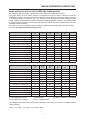
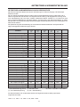
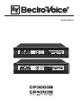
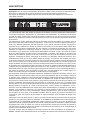
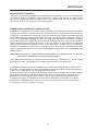
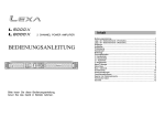
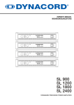
OWNER‘S MANUAL
BEDIENUNGSANLEITUNG
MODE D‘EMPLOI
CONTENTS
IMPORTANT SAFETY INSTRUCTIONS
IMPORTANT SERVICE INSTRUCTIONS
DESCRIPTION
UNPACKING & WARRANTY
INSTALLATION NOTES
FRONT VIEW
REAR VIEW
INPUT A / INPUT B
PARALLEL
POWER AMP OUTPUT
BRIDGED MODE
GROUND-LIFT SWITCH
MAINS INPUT
SPECIFICATIONS / TECHNISCHE DATEN
BLOCK DIAGRAM
DIMENSIONS / ABMESSUNGEN
.......................
.......................
.......................
.......................
.......................
.......................
.......................
.......................
.......................
.......................
.......................
.......................
.......................
.......................
.......................
.......................
3
3
4
5
5
6
7
7
7
8
8
8
8
30
31
32
WICHTIGE SICHERHEITSHINWEISE
WICHTIGE SERVICEHINWEISE
BESCHREIBUNG
AUSPACKEN & GARANTIE
INSTALLATIONSHINWEISE
FRONTSEITE
RÜCKSEITE
INPUT A / INPUT B
PARALLEL
ENDSTUFENAUSGÄNGE
BRIDGED MODE
GROUND-LIFT SCHALTER
NETZEINGANG
NETZBETRIEB & WÄRMEENTWICKLUNG
SPECIFICATIONS / TECHNISCHE DATEN
BLOCK DIAGRAM
DIMENSIONS / ABMESSUNGEN
.......................
.......................
.......................
.......................
.......................
.......................
.......................
.......................
.......................
.......................
.......................
.......................
.......................
.......................
.......................
.......................
.......................
13
13
14
15
15
16
17
17
17
18
18
18
18
19
30
31
32
IMPORTANTES INFORMATIONS DE SÉCURITÉ
INSTRUCTIONS DE RÉPARATION IMPORTANTES
DESCRIPTION
DÉBALLAGE ET GARANTIE
REMARQUES SUR L’INSTALLATION
FACE AVANT
PANNEAU ARRIÈRE
INPUT A / INPUT B
PARALLEL
SORTIE DE AMPLI DE PUISSANCE
GROUND-LIFT
ENTRÉE SECTEUR
SECTEUR ET TEMPÉRATURE RÉSULTANTE
SPECIFICATIONS
BLOCK DIAGRAM
DIMENSIONS
.......................
.......................
.......................
.......................
.......................
.......................
.......................
.......................
.......................
.......................
.......................
.......................
.......................
.......................
.......................
.......................
23
23
24
25
25
26
27
27
27
28
28
28
29
30
31
32
).(!,4
MATIÈRES
2
IMPORTANT SAFETY INSTRUCTIONS
The lightning flash with arrowhead symbol, within an
equilateral triangle is intended to alert the user to the
presence of uninsulated „dangerous voltage“ within
the product’s enclosure that may be of sufficient
magnitude to constitute a risk of electric shock to
persons.
1.
2.
3.
4.
5.
6.
7.
8.
9.
10.
11.
12.
13.
14.
15.
16.
The exclamation point within an equilateral triangle
is intended to alert the user to the presence of
important operating and maintance (servicing)
instructions in the literature accompanying the
appliance.
Read these instructions.
Keep these instructions.
Heed all warnings.
Follow all instructions.
Do not use this apparatus near water.
Clean only with a dry cloth.
Do not block any ventilation openings. Install in accordance with the manufactures instructions.
Do not install near any heat sources such as radiators, heat registers, stoves, or other apparatus
(including amplifiers) that produce heat.
Do not defeat the safety purpose of the polarized or grounding-type plug. A polarized plug has two blades
with one wider than the other. A grounding type plug has two blades and a third grounding prong. The wide
blade or the third prong are provided for your safety. If the provided plug does not fit into your outlet, consult an
electrican for replacement of the absolete outlet.
Protect the power cord from being walked on or pinched particularly at plugs, convenience receptacles,
and the point where they exit from the apparatus.
Only use attachments/accessories specified by the manufacturer.
Unplug this apparatus during lightning storms or when unused for long periods of time.
Refer all servicing to qualified service personnel. Servicing is required when the apparatus has been damaged
in any way, such as power-supply cord or plug is damaged, liquid has been spilled or objects have fallen into the
apparatus, the apparatus has been exposed to rain or moisture, does not operate normally, or has been dropped.
Do not expose this equipment to dripping or splashing and ensure that no objects filled with liquids, such as vases,
are placed on the equipment.
To completely disconnect this equipment from the AC Mains, disconnect the power supply cord plug from the AC
receptacle.
The mains plug of the power supply cord shall remain readily operable.
Management of WEEE (waste electrical and electronic equipment) (applicable in Member States of the European
Union and other European countries with individual national policies on the management of WEEE) The symbol on
the product or on its packaging indicates that this product may not be treated as regular household waste, but has
to be disposed through returning it at a Telex dealer.
IMPORTANT SERVICE INSTRUCTIONS
CAUTION:
1.
2.
3.
4.
5.
6.
7.
8.
These servicing instructions are for use by qualified personnel only. To reduce the risk of
electric shock, do not perform any servicing other than that contained in the Operating
Instructions unless you are qualified to do so. Refer all servicing to qualified service personnel.
Security regulations as stated in the EN 60065 (VDE 0860 / IEC 65) and the CSA E65 - 94 have to be obeyed when
servicing the appliance.
Use of a mains separator transformer is mandatory during maintenance while the appliance is opened, needs to be
operated and is connected to the mains.
Switch off the power before retrofitting any extensions, changing the mains voltage or the output voltage.
The minimum distance between parts carrying mains voltage and any accessible metal piece (metal enclosure),
respectively between the mains poles has to be 3 mm and needs to be minded at all times. The minimum distance
between parts carrying mains voltage and any switches or breakers that are not connected to the mains (secondary
parts) has to be 6 mm and needs to be minded at all times.
Replacing special components that are marked in the circuit diagram using the security symbol (Note) is only
permissible when using original parts.
Altering the circuitry without prior consent or advice is not legitimate.
Any work security regulations that are applicable at the location where the appliance is being serviced have to be
strictly obeyed. This applies also to any regulations about the work place itself.
All instructions concerning the handling of MOS - circuits have to be observed.
NOTE:
SAFETY COMPONENT ( MUST BE REPLACED BY ORIGINAL PART )
3
DESCRIPTION
Congratulations! With buying an Electro-Voice CP-Series power amplifier you have chosen a state-ofthe-art appliance that employs most advanced technology.
CP-Series power amps combine outstanding audio performance, highest reliability and operational
safety.
The audio performance of CP-Series power amps are simply extraordinary. The new switchmode power
supply technology, completely designed from scratch and the consistent use of Class-H technology
provide extensive headroom far above the stated nominal output and conspicuous reduction in leakage
power at the same time.
The employed switching power supply combines the headroom-advantage of a transformer power
amplifier with low weight of a pulsed power supply unit resulting in an improved performance-to-weight
ratio. Special attention had been given to high efficiency and interference immunity already in the
designing stage with the result that trouble-free operation of CP-Series power amps is possible even in
EMV-critical environments.
The power amplification stages of the CP3000S follow Class-H technology design, i.e. the power
amp provides extremely fast, signal-dependent operating voltage switching, which, results in doubling
the regular supply voltage when needed. Compared to Class-AB power amps, Class-H power amps
generate by far less power dissipation at identical output. Consequently, reduced leakage power or
dissipation is synonymous to less waste heat. In other words: energy is used more efficiently! As a result,
installing Class-H power amps within rack shelf systems is possible with less space between appliances.
In addition to that and despite offering identical output, power consumption is a lot less than in Class-AB
operation.
Being protected against thermal and electrical overload, short circuit and the occurrence of HF/DC at
the outputs, Electro-Voice CP-SERIES power amps fulfill even the most demanding requirements of
Pro-Audio touring applications. Back-EMF-Protection eliminates the risk of the output transistors being
damaged by electrical energy back-feed. The power outputs are switched via relay with a time delay
during soft-start and an inrush current limiter additionally prevents mains fuses from blowing.
Mechanical construction and workmanship also comply with the highest precision manufacturing
standards. The robust chassis is extremely rigid which makes it especially suitable for wearing touring
applications. Two three-speed high performance fans (off/slow/fast) guarantee outstanding thermal
stability at absolute low running noise. Front-to-rear ventilation allows trouble-free operation even in
smaller amp-racks. The electronically balanced inputs are carried out via XLR-type connectors. DirectOuts for through connecting the audio signal are also provided via XLRM-type connectors. Input Routing
allows selecting DUAL (stereo) or PARALLEL (monaural) operation mode. By means of the separate
BRIDGED OUT-connector and a Bridged Mode-switch, switching to “Mono Bridged” operation is truly
uncomplicated as well. The recessed mounted dB-scaled level controls ensure reliable protection against
mechanical damage. These particularly precise, secure to operate detent-potentiometers are located
on the front panel. CP-Series power amps provide the opportunity for retrofitting an internal analogue
signal processor board with x-over and filter functions. The easily readable LED display provides a quick
overview of the power amp’s current operational status. The power outputs CHANNEL A, CHANNEL
B and BRIDGED OUT are carried out as extremely durable SPEAKON-type connectors. Also located
on the rear panel is a Ground-lift switch, which, when needed, helps eliminating ground-noise loops by
separating the power amp’s enclosure from the circuit ground. In normal operation, all CP-Series power
amps are capable of driving loads as low as 2ohms. In Mono-Bridged mode the allowable minimum load
is 4ohms.
This owner’s manual outlines and explains several other features of your CP-SERIES power amplifier.
Please, make sure to carefully read all of it and mind the instructions.
4
DESCRIPTION
UNPACKING & WARRANTY
Carefully open the packaging and take out the power amplifier. Next to the power amplifier itself, the
package also includes this owner’s manual, a mains cord and the warranty certificate. Keep the original
invoice, which states the purchase/delivery date together with the warranty certificate at a safe place.
INSTALLATION NOTES
Generally, installing or mounting CP-Series power amps should be carried out in a way that guarantees
continuously unopposed front-to-rear air circulation. Installation of appliances with opposite air circulation
within one cabinet or closed rack shelf system is not recommendable. When including appliances in a
closed cabinet or rack shelf system make sure to provide sufficient ventilation. Leave a gap of at least
60mm x 330mm (up to the cabinet’s top ventilation louvers) for air circulation between the rear of the
power amplifier and the cabinet’s/rack’s rear inner wall. Make sure to leave at least 100mm of space
above the cabinet or rack shelf system. Since temperatures inside of the cabinet or rack shelf system
can easily rise up to 40°C during operation, bearing in mind the maximally allowable environmental
temperatures for all other appliances installed in the same rack shelf system is mandatory (also refer to
“MAINS OPERATION AND RESULTING TEMPERATURE”).
Caution: For trouble-free operation exceeding the maximally allowable environmental
temperature of +40°C is not permissible.
To prevent the front panel from bending, the use of installation rails or optionally available “rear-rackmount” rails is obligatory when installing the appliance in a rack shelf system or cabinet.
The power amplifier has to be protected against: dripping or splashing water, direct sunlight, high
temperatures or direct influence of heat sources, high humidity, extensive dust and vibrations.
If guaranteeing the listed requirements is not possible on a long-term basis, regular servicing is
absolutely mandatory to prevent the power amplifier from possible failure, mainly being caused by
negative environmental effects.
The power amplifier has to be protected against: dripping or splashing water, direct sunlight, high
temperatures or direct influence of heat sources, high humidity, extensive dust and vibrations.
Condensation on internal parts may occur when transporting the power amplifier from a cold into a
warmer environment. In that case operation is only permissible after the appliance has gained the new
temperature (after approximately one hour). If foreign objects or liquids have entered the power amp’s
enclosure, make sure to immediately separate the appliance from the mains network and contact an
authorized service center for inspection before continuing operation.
FCC INFORMATION (U.S.A)
1. IMPORTANT: Do not modify this unit! Changes or modifications not expressly approved
by the manufacturer could void the user`s authority, granted by the FCC, to operate the
equipment.
2. NOTE : This equipment has been tested and found to comply with the limits for a Class
B digital device, pursuant to Part 15 of the FCC Rules. These limits are designed to
provide reasonable protection against harmful interference in a residential installation.
This equipment generates, uses and can radiate radio frequency energy and, if not
installed and used in accordance with the instructions, may cause harmful interference
to radio communications. However, there is no guarantee that interference will not occur
in a particular installation. If this equipment does cause harmful interference to radio
or television reception , which can be determined by turning the equipment off and on,
the user is encouraged to try to correct the interference by one or more of the following
measures:
• Reorient or relocate the receiving antenna
• Increase the separation between the equipment and receiver.
• Connect the equipment into an outlet on a circuit different from that to which the
receiver is connected.
• Consult the dealer or an experienced radio/TV technician for help.
5
FRONT PANEL
Use the POWER switch located on the front panel to power-on the appliance. The soft-start function
protects against current inrush peaks on the mains, which in addition prevents the mains line protection
switch from activating during power-on. The loudspeaker outputs are activated via relay switching with
a delay of approximately 3 seconds to efficiently attenuate eventual power-on noise. The PROTECT
LED lights during the delay time. This is normal, confirming the immaculate operation of the protection
circuitry.
This indicator lights when the power amplifier has been switched on. Causes for
the POWER-indicator not lighting are: the appliance is not connected to the mains
network or a defective primary fuse.
The PROTECT LED lights indicating that one of the internal protection circuits
against thermal overload, short-circuit, Back-EMF, HF-occurrence at the output,
etc., has been activated. The output relays interrupt the connected loads from
the power amps while input signals are interrupted as well, preventing the connected
loudspeaker systems and the power amplifier itself from being damaged.
Whatever caused the fault – e.g. a short-circuited speaker cable – needs to be
remedied. In case of thermal overload you have to wait until the power amplifier
automatically regains normal operation.
The SIGNAL LED lights as soon as an audio signal of approximately 30dB below full
modulation is present at the output. The LED is dimmed when speaker cables are
short-circuited or a protection circuit has been activated.
The 0dB LED lights whenever the power amplifier is driven at its limits. Higher input
voltage does not result in higher peak output voltage. In addition, the 0dB indicator
comes in handy when adjusting external limiters.
This indicator lights as soon as the integrated dynamic audio signal limiter is
activated and the power amplifier is driven at the clipping limit or generally
at its maximum capacity. Short-term blinking is not a problem, because the internal
limiter trims input levels of up to +21dBu down to an S/N-ratio of approximately 1%.
If, on the other hand, this LED lights constantly, reducing the volume is
recommended to prevent the loudspeaker systems connected from being damaged
by probable overload.
Detent potentiometers scaled in dB (steps of 1dB) for
adjusting the power amp’s overall amplification. To prevent
distortion in mixing consoles connected to the amp, setting
these controls to a value between 0dB and -6dB is generally
recommended. The dB-scale provides direct indication of the
control attenuation applied to the fixed internal amplification.
6
REAR PANEL
INPUT A / INPUT B
The inputs INPUT A & INPUT B are electronically balanced
offering input sensitivity of
+5.8dBu /1.51V (CP3000S)
+7.0dBu /1.74V (CP4000S)
for direct connection of mixing consoles, signal processors, etc.
The XLR-type connectors OUTPUT A & OUTPUT B are prepared
for „through-connecting“ input signals to additional external power
amps. The input signal is directly routed to these output connectors. There are no repeaters or other
electronic components within that signal path. Accordingly, input and output connectors of the
corresponding channel are interconnected in parallel, offering permanent electrical connection, without
regard to the setting of the Power-ON switch.
Although having XLR-type output connectors, some mixing console models provide unbalanced
output connection only. When using mixers with unbalanced outputs, bridging PIN1 and PIN3
of the power amp’s input connectors or leaving PIN3 of the cable’s plugs unconnected is
necessary. Otherwise, when feeding in unbalanced audio signals via PIN3 (b, -, „cold“) and PIN2
(a, +, „hot“), strange humming and HF-interference may occur, which very likely will damage the
power amplifier and/or the connected speaker cabinets.
NF-CONNECTION CORDS
Choosing high-quality balanced cables (two conductors for the audio signal plus separate shielding
mesh) with XLR-type connectors is recommended for LF-signal connection. Although connecting unbalanced cables to the power amplifier inputs is possible as well, using balanced cables is always preferable. A great number of today’s audio appliances employ balanced outputs. With balanced cabling, the
shield connects all metal enclosure parts and therefore efficiently eliminates the introduction of external
interference – mostly noise and hum.
XLR-type connector pin-assignment
XLR (male)
XLR (female)
PARALLEL
The input connectors of channel A and channel B are electrically connected in parallel
when the selector switch is set to PARALLEL. However, individually controlling the
volume of both channels is still possible via the corresponding level controls A and B.
DUAL
If the selector switch is set to DUAL, the audio signals of channels A and B are
independently amplified.
7
REAR PANEL
POWER AMPLIFIER OUTPUT CONNECTORS
Power amp output connection for the two channels
A (left) and B (right) is provided via SPEAKON-type
output connectors. A plastic cover to prevent inadvertent
erroneous connection protects the BRIDGED OUT
connector. Remove the cover only when actually operating
the power amplifier in Bridged-Mode.
CAUTION!
Pins 2+/2- of the CHANNEL A SPEAKON output, which
normally are not in use, are also connected to output B to
ensure comfortable connection of 2-way speaker cabinets
(e.g in Bi-Amping Mode) when using 4-wire Speakon
cables.
To prevent short-circuit and/or to protect your speaker systems from being damaged when connecting
the cabinets, please make sure to mind the Low- and High channels’ specific pin-assignments!
If, for example, the subwoofer audio signal is used to feed a tweeter, it is more than likely that this will
instantly destroy the HF-driver’s coil.
WARNING:
The speaker output terminals are marked with a symbol “
”, which signifies that these
terminals present a shock hazard to the user.
BRIDGED MODE
With the BRIDGED-MODE switch being engaged, using the channel A input
for audio signal feed is mandatory, since input B provides no function. While
the amplifier of channel A operates as usual. Additionally, the audio signal is
internally inverted and routed to the amplifier of channel B. Both amps – A
and B – now work in push-pull operation to provide doubled output voltage at
the BRIDGED-OUT connector.
The regular output voltage of each amplifier channel A + B is still present at the
corresponding output connectors CHANNEL A and CHANNEL B. However,
using these signals is not recommendable because of the aforementioned
phase inversion. Operating the power amp in Bridged Mode with loads of
2ohms connected is not allowable.
CAUTION: Operating the power amplifier in Bridged-Mode may result in extremely high voltages
being present at the BRIDGED OUT connector. The connected loudspeaker systems have to be
designed for handling such high voltages. Please carefully read the power handling specifications
as stated in the documentation of the according loudspeaker system and make sure to check
whether they are in compliance with the output capacity specifications of the power amplifier.
GROUND-LIFT SWITCH
The ground-lift switch allows eliminating noise loops. When operating the
power amplifier in a 19“ rack-shelf system or cabinet together with other
equipment, setting the switch to its GROUNDED position is recommended.
When operating the power amplifier together with appliances with differing
ground potentials, set the switch to its UNGROUNDED position
MAINS INPUT
Under normal circumstances, the mains fuse only blows in case of fault.
Replacing the fuse is only permissible for authorized service personnel
using a new fuse of the same type with identical amperage, voltage and
blow characteristics. The high-performance mains cord supplied with your
power amplifier complies with applicable safety regulations, plus that its
diameter corresponds to the power amp’s power output capacity. Whenever
possible make sure to use the supplied mains cord for connecting the power amp to the mains network.
Using a different mains cord with a smaller diameter results in higher leakage, consequently reducing
the amplifier’s maximum power output capacity.
8
MAINS OPERATION & RESULTING
MAINS OPERATION & RESULTING POWER AMP TEMPERATURES
The following tables are useful in determining power supply and cabling requirements.
The power drawn from the mains network is converted into acoustic output to feed the connected
loudspeaker systems plus heat. The difference between drawn power and dispensed power is referred
to as leakage power or dissipation (Pd). The amount of heat resulting from power dissipation might
remain inside of a rack-shelf and needs to be diverted using appropriate measures. The following table
is meant as auxiliary means for calculating temperatures inside of rack-shelf systems/cabinets and the
ventilation efforts necessary.
The column “Pd” lists the leakage power in relation to different operational states. The column “BTU/
hr” shows the dispensed heat amount per hour.
CP3000S
idle
Umains
[V]
Imains
[A]
Pmains
[W]
Pout
[W]
Pd (5)
[W]
BTU/hr(3)
230
0.8
80
-
80
273
Max. Output Power @ 8Ω
(1)
230
11.0
1780
2 x 600
580
1980
Max. Output Power @ 4Ω
(1)
230
19.5
3240
2 x 1100
1040
3549
1/3 Max. Output Power @ 4Ω
(1)
230
11.3
1740
2 x 366
1008
3439
1/8 Max. Output Power @ 4Ω
(1)
230
4.6
640
2 x 137
366
1249
1/8 Max. Output Power @ 4Ω
(2)
230
6.0
850
2 x 137
576
1965
(2),(4)
253
6.1
950
2 x 166
618
2109
(1)
1/8 Max. Output Power @ 4Ω
Normal Mode (-10dB) @ 4Ω
230
4.2
580
2 x 110
360
1230
(1)
230
17.6
2860
2 x 900
1060
3617
(1)
230
12.6
1980
2 x 450
1080
3685
Rated Output Power (0dB) @ 4Ω
Alert (Alarm) Mode (-3dB) @ 4Ω
Max. Output Power @ 2Ω
(1)
230
30.3
5280
2 x 1600
2080
7100
1/8 Max. Output Power @ 2Ω
(1)
230
7.0
1030
2 x 200
630
2150
1/8 Max. Output Power @ 2Ω
(2)
230
8.4
1250
2 x 200
850
2900
Umains
[V]
Imains
[A]
Pmains
[W]
Pout
[W]
Pd (5)
[W]
BTU/hr(3)
230
1.3
145
-
145
495
230
15.7
2500
2 x 900
700
2388
CP4000S
idle
Max. Output Power @ 8Ω
(1)
Max. Output Power @ 4Ω
(1)
230
26.0
4400
2 x 1500
1400
4777
1/3 Max. Output Power @ 4Ω
(1)
230
14.7
2320
2 x 500
1320
4504
1/8 Max. Output Power @ 4Ω
(1)
230
6.9
990
2 x 188
615
2098
1/8 Max. Output Power @ 4Ω
(2)
230
7.3
1070
2 x 188
695
2371
(2),(4)
253
7.7
1200
2 x 227
746
2546
(1)
2030
1/8 Max. Output Power @ 4Ω
Normal Mode (-10dB) @ 4Ω
230
6.3
895
2 x 150
595
(1)
230
23.5
3900
2 x 1200
1500
5118
(1)
230
16.4
2630
2 x 600
1430
4879
Rated Output Power (0dB) @ 4Ω
Alert (Alarm) Mode (-3dB) @ 4Ω
(1)
230
40.7
7200
2 x 2100
3000
10236
1/8 Max. Output Power @ 2Ω
(1)
230
10.3
1525
2 x 263
1000
3412
1/8 Max. Output Power @ 2Ω
(2)
230
10.4
1535
2 x 263
1010
3446
Max. Output Power @ 2Ω
(1) Sine Modulation (1kHz)
(4) 10% Mains Over Voltage
(2) VDE-Noise
(5) Pd = Leakage Power
(3) 1BTU = 1055.06J = 1055.06Ws
The following factors allow direct proportional calculation of the mains current Imain for different mains
supply voltages:
100V = 2.3; 120V = 1.9; 220V = 1.05; 240V = 0.96
9
NOTES
10
BEDIENUNGSANLEITUNG
INHALT
WICHTIGE SICHERHEITSHINWEISE
WICHTIGE SERVICEHINWEISE
BESCHREIBUNG
AUSPACKEN & GARANTIE
INSTALLATIONSHINWEISE
FRONTSEITE
RÜCKSEITE
INPUT A / INPUT B
PARALLEL
ENDSTUFENAUSGÄNGE
BRIDGED MODE
GROUND-LIFT SCHALTER
NETZEINGANG
NETZBETRIEB & WÄRMEENTWICKLUNG
SPECIFICATIONS / TECHNISCHE DATEN
BLOCK DIAGRAM
DIMENSIONS / ABMESSUNGEN
12
.......................
.......................
.......................
.......................
.......................
.......................
.......................
.......................
.......................
.......................
.......................
.......................
.......................
.......................
.......................
.......................
.......................
13
13
14
15
15
16
17
17
17
18
18
18
18
19
30
31
32
WICHTIGE SICHERHEITSHINWEISE
Das Blitzsymbol innerhalb eines gleichseitigen Dreiecks soll den Anwender auf nicht isolierte Leitungen
und Kontakte im Geräteinneren hinweisen, an denen
hohe Spannungen anliegen, die im Fall einer
Berührung zu lebensgefährlichen Stromschlägen
führen können.
1.
2.
3.
4.
5.
6.
7.
8.
9.
10.
11.
12.
13.
14.
15.
16.
Das Ausrufezeichen innerhalb eines gleichseitigen
Dreiecks soll den Anwender auf wichtige Bedienungssowie Servicehinweise in der zum Gerät gehörenden Literatur aufmerksam machen.
Lesen Sie diese Hinweise.
Heben Sie diese Hinweise auf.
Beachten Sie alle Warnungen.
Richten Sie sich nach den Anweisungen.
Betreiben Sie das Gerät nicht in unmittelbarer Nähe von Wasser.
Verwenden Sie zum Reinigen des Gerätes ausschließlich ein trockenes Tuch.
Verdecken Sie keine Lüftungsschlitze. Beachten Sie bei der Installation des Gerätes stets die entsprechenden
Hinweise des Herstellers.
Vermeiden Sie die Installation des Gerätes in der Nähe von Heizkörpern, Wärmespeichern, Öfen oder anderer
Wärmequellen.
Achtung: Gerät nur an Netzsteckdose mit Schutzleiteranschluss betreiben. Setzen Sie die Funktion des
Schutzleiteranschlusses des mitgelieferten Netzanschlusskabels nicht außer Kraft. Sollte der Stecker des
mitgelieferten Kabels nicht in Ihre Netzsteckdose passen, setzen Sie sich mit Ihrem Elektriker in Verbindung.
Sorgen Sie dafür, dass das Netzkabel nicht betreten wird. Schützen Sie das Netzkabel vor Quetschungen
insbesondere am Gerätestecker und am Netzstecker.
Verwenden Sie mit dem Gerät ausschließlich Zubehör/Erweiterungen, die vom Hersteller hierzu vorgesehen sind.
Ziehen Sie bei Blitzschlaggefahr oder bei längerem Nichtgebrauch den Netzstecker.
Überlassen Sie sämtliche Servicearbeiten und Reparaturen einem ausgebildeten Kundendiensttechniker.
Servicearbeiten sind notwendig, sobald das Gerät auf irgendeine Weise beschädigt wurde, wie z.B. eine
Beschädigung des Netzkabels oder des Netzsteckers, wenn eine Flüssigkeit in das Gerät geschüttet wurde oder ein
Gegenstand in das Gerät gefallen ist, wenn das Gerät Regen oder Feuchtigkeit ausgesetzt wurde, oder wenn es nicht
normal arbeitet oder fallengelassen wurde.
Stellen Sie bitte sicher, dass kein Tropf- oder Spritzwasser ins Geräteinnere eindringen kann. Stellen Sie keine mit
Flüssigkeiten gefüllten Objekte, wie Vasen oder Trinkgefässe, auf das Gerät.
Um das Gerät komplett spannungsfrei zu schalten, muss der Netzstecker gezogen werden.
Beim Einbau des Gerätes ist zu beachten, dass der Netzstecker leicht zugänglich bleibt.
Entsorgung von gebrauchten elektrischen und elektronischen Geräten (Anzuwenden in den Ländern der
Europäischen Union und anderen europäischen Ländern mit einem separaten Sammelsystem für diese
Geräte) Das Symbol auf dem Produkt oder seiner Verpackung weist darauf hin, dass dieses Produkt nicht
als normaler Haushaltsabfall zu behandeln ist, sondern bei einem Telex Händler abgegeben werden muss.
WICHTIGE SERVICEHINWEISE
ACHTUNG:
Diese Servicehinweise sind ausschliesslich für qualifiziertes Servicepersonal vorgesehen.
Um die Gefahr eines elektrischen Schlages zu vermeiden, führen Sie keine Wartungsarbeiten durch,
die nicht in der Bedienungsanleitung beschrieben sind, ausser Sie sind hierfür qualifiziert. Überlassen
Sie sämtliche Servicearbeiten und Reparaturen einem ausgebildeten Kundendiensttechniker.
1. Bei Reparaturarbeiten im Gerät sind die Sicherheitsbestimmungen nach EN 60065 (VDE 0860) einzuhalten.
2. Bei allen Arbeiten, bei denen das geöffnete Gerät mit Netzspannung verbunden ist und betrieben wird, ist ein Netz trenntransformator zu verwenden.
3. Vor einem Umbau mit Nachrüstsätzen, Umschaltung der Netzspannung oder sonstigen Modifikationen ist das Gerät
stromlos zu schalten.
4. Die Mindestabstände zwischen netzspannungsführenden Teilen und berührbaren Metallteilen
(Metallgehäuse) bzw. zwischen den Netzpolen betragen 3 mm und sind unbedingt einzuhalten.
Die Mindestabstände zwischen netzspannungsführenden Teilen und Schaltungsteilen, die nicht mit dem Netz
verbunden sind (sekundär), betragen 6 mm und sind unbedingt einzuhalten.
5. Spezielle Bauteile, die im Stromlaufplan mit dem Sicherheitssymbol gekennzeichnet sind (Note), dürfen nur durch
Originalteile ersetzt werden.
6. Eigenmächtige Schaltungsänderungen dürfen nicht vorgenommen werden.
7. Die am Reparaturort gültigen Schutzbestimmungen der Berufsgenossenschaften sind einzuhalten. Hierzu gehört
auch die Beschaffenheit des Arbeitsplatzes.
8. Die Vorschriften im Umgang mit MOS - Bauteilen sind zu beachten.
NOTE:
SAFETY COMPONENT ( MUST BE REPLACED BY ORIGINAL PART )
13
BESCHREIBUNG
Herzlichen Glückwunsch! Sie haben sich mit einer Endstufe der CP-SERIE von Electro-Voice für ein
Gerät modernster Technologie entschieden.
Die Endstufen der CP-Serie vereinen überragende Audio-Performance mit höchster Zuverlässigkeit
und Betriebssicherheit.
Die Übertragungseigenschaften der CP-Endstufe sind hervorragend. Durch eine völlig neu entwickelte Schaltnetzteiltechnologie und die konsequente Anwendung der Class H Technik wird ein großer
Headroom weit oberhalb der ausgewiesenen Nennleistung erzielt und gleichzeitig eine deutliche Reduzierung von Gewicht und Verlustleistung erreicht.
Das eingesetzte Schaltnetzteil vereint die Headroom-Vorteile einer Trafoendstufe mit den
Gewichtsvorteilen eines getakteten Netzteils. Dadurch wird ein ausgezeichnetes Leistungs-Gewicht
Verhältnis erreicht. Bei der Konstruktion wurde besonderes Augenmerk auf einen hohen Wirkungsgrad
und auf Störarmut gelegt. Somit ist auch ein Betrieb in EMV-kritischer Umgebung problemlos.
Die Endstufenblöcke der CP3000S sind in Class H Technik aufgebaut. D.h. die Endstufe verfügt über
eine extrem schnelle, signalabhängige Umschaltung der Betriebsspannung, die im Bedarfsfall eine
Verdopplung der normalen Versorgungsspannung bewirkt. Im Vergleich zu Class AB Endstufen wird
bei Endstufen mit Class H Technik erheblich weniger Verlustleistung bei gleicher Ausgangsleistung
erzeugt. Weniger Verlustleistung ist gleichbedeutend mit weniger Abwärme oder besser gesagt mit
einer besseren Effizienz bzw. Energiebilanz des Gerätes. Endstufen in Class H Technik lassen sich
daher mit einer entsprechend höheren Packungsdichte im Rack bzw. Gestellschrank verbauen. Darüber
hinaus ist die netzseitige Stromaufnahme wesentlich geringer als im Class AB Betrieb, bei gleicher
Ausgangsleistung.
Die Electro-Voice - Endstufen der CP- SERIE erfüllen auch die extremen Anforderungen des
harten Tour-Betriebs. Sie sind gegen Überhitzung, Überlast, Kurzschluß sowie Hochfrequenz
und Gleichspannung am Ausgang geschützt. Eine Beschädigung der Endtransistoren durch
Rückeinspeisung elektrischer Energie wird durch die Back-EMF Schutzschaltung verhindert. Beim
Softstart werden die Leistungsausgänge über Relais verzögert zugeschaltet. Zusätzlich verhindert eine
Einschaltstrombegrenzung das Ansprechen von Netzsicherungen.
Höchste Präzision ist auch in der mechanischen Konstruktion und Verarbeitung gewährleistet. Das
robuste Chassis ist besonders verwindungssteif und speziell auf die Belastungen des harten Tourbetriebs
ausgelegt. Die thermische Stabilität wird durch zwei 3-Stufen Lüfter (off/slow/fast) mit sehr niedrigem
Geräuschpegel gewährleistet. Die Front-to-Rear Luftführung, erlaubt den Betrieb auch in großen und
schmalen Endstufen-Racks. Die Eingänge sind elektronisch symmetrisch auf XLR-Buchsen geführt.
Direct-Outs zum Durchschleifen des Signals sind ebenfalls in Form von XLR-Buchsen (male) praktischer
Standard. Über das Input Routing können die Betriebsarten DUAL (Stereo) oder PARALLEL (Mono)
gewählt werden. Außerdem ist der „Mono Bridged“ –Betrieb über die separate BRIDGED OUT Buchse
und den Bridged Mode Umschalter sehr einfach zu realisieren. Auf der Frontblende sitzen die in dB
skalierten Levelregler, die als besonders präzise, bediensichere Rastpotis ausgeführt und zum Schutz vor
mechanischer Beschädigung in der Frontblende versenkt sind. Die CP-Serie bietet intern die Möglichkeit
zur Nachrüstung einer analogen Signalprozessorkarte mit Frequenzweichen- und Filterfunktionen.
Eine schnelle Übersicht über den aktuellen Betriebszustand der Endstufen vermittelt das leicht
ablesbare LED-Display. Die Leistungsausgänge CHANNEL A, CHANNEL B und BRIDGED OUT sind
als extrem zuverlässige SPEAKON-Buchsen ausgeführt. Ebenfalls auf der Rückwand befinden sich
ein Groundlift-Schalter, der bei Bedarf das Gehäuse der Endstufe von der Schaltungsmasse trennt und
somit Brummschleifen verhindern hilft. Alle CP- Endstufen können im Normalbetrieb an Lasten bis hinab
zu 2 Ohm und im Brückenbetrieb bis zu minimal 4 Ohm eingesetzt werden.
Mit dieser Bedienungsanleitung werden Sie noch viele weitere Eigenschaften der Endstufen aus der
CP-SERIE kennenlernen. Lesen Sie deshalb bitte aufmerksam weiter.
14
BESCHREIBUNG
AUSPACKEN & GARANTIE
Öffnen Sie die Verpackung und entnehmen Sie die Endstufe. Zusätzlich zu dieser
Bedienungsanleitung liegen dem Gerät ein Netzkabel, und die Garantiekarte bei. Bewahren Sie zur
Garantiekarte auch den Kaufbeleg, der den Termin der Übergabe festlegt, auf.
INSTALLATIONSHINWEISE
Generell sind die Endstufen so aufzustellen oder zu montieren, dass die Luftzufuhr an der Frontseite
und die Entlüftung an der Geräterückseite nicht behindert wird. Die Belüftungsrichtung ist also „Frontto-Rear“. Geräte mit umgekehrter Luftführung sollen möglichst nicht im gleichen Rack/Schrank verbaut
werden. Für den Einbau in Gehäuse und Gestellschränke ist zu beachten, dass eine ausreichende
Belüftung der Geräte möglich ist. Zwischen der Endstufen Rückseite und der Schrank/Rack-Innenseite
ist ein freier Luftkanal bis zur oberen Rack- oder Schrankentlüftung von mindestens 60mm x 330mm
vorzusehen. Oberhalb des Schrankes soll ein freier Raum von mindestens 100mm für die Entlüftung zur
Verfügung stehen. Da beim Betrieb die Temperatur im Gehäuse- oder Schrank bis zu 40°C ansteigen
kann, muss die maximal zulässige Umgebungstemperatur der übrigen im Gestellschrank befindlichen
Geräte beachtet werden (siehe auch Kapitel: NETZBETRIEB UND WÄRMEENTWICKLUNG ).
Achtung: Die max. Umgebungstemperatur von +40°C soll für störungsfreien Betrieb nicht
überschritten werden.
Beim Einbau in Gestellschränken oder Transportracks, sollen in jedem Fall handelsübliche Einbauschienen oder die optional erhältlichen „Rear-rackmount“ Schienen verwendet werden, um ein Verwinden der Frontblende zu verhindern.
Die Endstufe ist zu schützen vor: Tropf- oder Spritzwasser, direkter Sonnenbestrahlung, hoher
Umgebungstemperatur oder unmittelbarer Einwirkung von Wärmequellen, hoher Luftfeuchtigkeit,
starken Staubablagerungen und starken Vibrationen.
Können die angeführten Forderungen nicht dauerhaft gewährleistet werden, so ist eine regelmäßige
Wartung der Endstufe zwingend erforderlich, um etwaigen Ausfällen vorzubeugen, die wesentlich durch
negative Umwelteinflüsse entstehen können
Wenn die Endstufe direkt von einem kalten an einen warmen Ort gebracht wird, kann sich Feuchtigkeit
auf Innenteilen niederschlagen. Das Gerät darf erst in Betrieb genommen werden, wenn es sich auf
die geänderte Temperatur erwärmt hat (nach etwa einer Stunde). Sollte ein fester Gegenstand oder
Flüssigkeit in das Gehäuse gelangen, trennen Sie sofort das Gerät vom Netz und lassen Sie das Gerät
von einer autorisierten Servicestelle überprüfen, bevor Sie es weiterverwenden.
15
FRONTSEITE
Mit dem POWER Schalter auf der Frontblende wird das Gerät eingeschaltet. Eine Softstart- Schaltung
vermeidet dabei Einschaltstromspitzen auf der Netzleitung. Dadurch wird verhindert, dass der
Leitungsschutzschalter des Stromnetzes beim Einschalten der Endstufe anspricht. Die Lautsprecher
werden über die Ausgangsrelais um ca. 3 Sekunden verzögert zugeschaltet, wodurch etwaige
Einschaltgeräusche effektiv unterdrückt werden, die ansonsten in den Lautsprechern hörbar wären.
Während dieser Verzögerung leuchtet die PROTECT LED. Dies ist normal und bestätigt die einwandfreie
Funktion der Schutzschaltungen.
Diese LED leuchtet auf, wenn die Endstufe eingeschaltet ist. Falls die POWER Anzeige nicht leuchtet, ist das Gerät nicht mit dem Stromnetz verbunden, oder die
Primärsicherung defekt.
Wenn die PROTECT-Anzeige aufleuchtet, hat eine der internen Schutzschaltungen
wie Übertemperatur, Kurzschluss, Back-EMF, Hochfrequenz am Ausgang.... angesprochen. Die Endstufen werden in diesem Fall über die Ausgangsrelais von der Last
getrennt, und die Signalzufuhr unterbrochen um etwaige Schäden an den Lautsprechern oder der Endstufe selbst zu verhindern.
Die Fehlerursache, beispielsweise eine kurzgeschlossene Lautsprecherleitung muss
beseitigt werden. Bei Überhitzung muss einige Zeit gewartet werden, bis die Endstufe sich selbständig wieder in den normalen Betriebszustand schaltet.
Die SIGNAL-LED beginnt ca. 30dB unter Vollaussteuerung zu leuchten und zeigt
an, dass generell ein Signal am Ausgang vorhanden ist. Bei Kurzschluss von
Lautsprecherleitungen oder Ansprechen einer Schutzschaltung verlischt diese
Anzeige.
Die 0dB Anzeige leuchtet auf, wenn die Endstufe an der Aussteuergrenze berieben wird. Eine höhere Eingangsspannung hat keine Erhöhung der Spitzenaus
gangsspannung zur Folge. Die 0dB Anzeige kann auch bei der Einstellung von
externen Limitern sehr hilfreich sein.
Diese Anzeige leuchtet auf, sobald einer der eingebauten dynamische Audio-Limiter
anspricht und die Endstufe über der Aussteuerungsgrenze oder generell im Grenzbereich betrieben wird. Kurzzeitiges Aufleuchten ist dabei unproblematisch, da der
interne Limiter Eingangspegel bis zu +21dBu auf einen akustisch unkritischen Klirrfaktor von ca. 1% ausregeln kann. Leuchtet diese LED jedoch dauerhaft, sollte die
Lautstärke reduziert werden, um etwaige Überlastungsschäden der angeschlosse
nen Lautsprecherboxen zu vermeiden.
In dB-skalierte Rastpotis ( 1 dB Schritte ) zur Anpassung der
Gesamtverstärkung der Endstufe. Zur Vermeidung von Verzerrungen in vorgeschalteten Mischpulten sollten diese
Regler normalerweise zwischen 0dB und -6dB eingestellt
werden. Die Beschriftung zeigt unmittelbar die Reglerdämpfung mit der die intern festgelegte Verstärkung verändert
wird.
16
RÜCKSEITE
INPUT A / INPUT B
Die Eingänge INPUT A & INPUT B sind elektronisch symmetrisch
mit einer Eingangsempfindlichkeit von
+5.8dBu /1.51V (CP3000S)
+7.0dBu /1.74V (CP4000S)
für den direkten Betrieb mit Mischpulten, Signalprozessoren
usw. ausgelegt.
Die XLR-Ausgangsbuchsen OUTPUT A & OUTPUT B
sind zum „Durchschleifen“ des Eingangssignals zu weiteren
Endstufen vorgesehen. Das Eingangssignal wird dabei direkt
auf die Ausgangsbuchsen gelegt, es befinden sich keine Zwischenverstärker oder andere elektronischen
Bauteile in diesem Pfad. Die Eingangs- und Ausgangsbuchsen des jeweiligen Kanals sind also direkt
elektrisch parallel geschaltet und damit unabhängig von der Stellung des Power-ON-Schalters
permanent miteinander verbunden.
Einige Mischpulte sind ausgangsseitig unsymmetrisch beschaltet obwohl als Ausgangssteckverbindung XLR Stecker vorgesehen sind. Falls ein Mischpult mit unsymmetrischen Ausgängen
verwendet wird, müssen an den Endstufeneingangsbuchsen PIN1 und PIN3 miteinander über
eine Brücke verbunden werden, oder der PIN3 am Verbindungskabel muß unbeschaltet bleiben.
Wird aus unsymmetrisch beschalteten Geräten über PIN3 (b, -, „kalt“) und PIN2 (a, +, „heiß“)
eingespeist, so können eigenartige Brummstörungen und hochfrequente Schwingungen
auftreten, die zu Endstufen- und Lautsprecherdefekten führen können.
NF-VERBINDUNGSKABEL
Als NF-Verbindung wählen Sie am besten symmetrisch ausgelegte Kabel (2 Signaladern + Schirmgeflecht) mit XLR-Stecker. Obwohl alle Endstufeneingänge auch unsymmetrisch beleget werden können, stellt ein symmetrisch ausgeführtes NF-Verbindungskabel die bessere Alternative dar. Die meisten Audiogeräte verfügen über symmetrisch aufgebaute Ausgänge. Der Schirm im Kabel verbindet bei
symmetrischer Signalführung alle metallischen Gehäuse und verhindert dadurch lückenlos ein Einkoppeln von externen Störsignalen, im wesentlichen Brummen, auf den Audiosignalpfad.
XLR-Steckerbelegung
XLR (male)
XLR (female)
PARALLEL
Steht der Wahlschalter in Position PARALLEL sind die Eingangsbuchsen Kanal A
und B elektrisch direkt parallel geschaltet. Die Lautstärke für Kanal A oder B kann
aber unabhängig voneinander mit den Levelreglern A oder B eingestellt werden.
DUAL
Steht der Wahlschalter in Stellung DUAL werden Kanal A und B getrennt verstärkt.
17
RÜCKSEITE
ENDSTUFENAUSGANGSBUCHSEN
Für die Endstufenkanäle A (Links) und B (Rechts) sind
jeweils professionelle SPEAKON Ausgangsbuchsen
vorhanden.
Diese mechanisch und elektrisch sichere Verbindung wird
allen Sicherheitsanforderungen gerecht und erlaubt die
Verwendung von Hochleistungslautsprecherkabeln von bis
zu 4 x 2,5mm2 Querschnitt.
Im Electro-Voice Zubehörprogramm finden Sie
Einzelstecker und Kupplungen sowie Hochleistungslautsprecherkabel.
Die BRIDGED OUT Buchse für den Brückenbetrieb ist mit
einem Kunststoffdeckel geschlossen, um Anschlußfehler
zu vermeiden. Entfernen Sie den Deckel nur, wenn Sie die
Endstufe tatsächlich im Brückenbetrieb verwenden wollen.
ACHTUNG!
Zum bequemen Anschluss von 2-Weg Lautsprechern (z.B im Bi-Amp Mode) über ein 4adriges
Speakon Kabel sind im CHANNEL A SPEAKON Ausgang auch die sonst unbenutzten 2+/2- Pins mit
dem Ausgang B verbunden.
Bitte beachten Sie beim Anschluss der Lautsprecher unbedingt die Beschaltung für Low- und HighKanal um Kurzschlüsse oder Lautsprecherdefekte zu vermeiden!
Warnung:
Das Symbol “ ”, das die Lautsprecheranschlüsse markiert, zeigt an, daß hier Spannungen
anliegen, die dem Anwender bei Berührung gesundheitlichen Schaden zufügen können.
BRIDGED MODE
Ist der Schalter BRIDGED-MODE gedrückt muß in den Kanal A eingespeist
werden. Der Input B hat dann keine Funktion.Die Endstufe im Kanal A wird
ganz normal angesteuert. Zusätzlich wird das Signal intern invertiert und
auf die Endstufe im Kanal B gelegt. Die Endstufen A und B arbeiten dann im
Gegentakt mit verdoppelter Ausgangsspannung auf die Ausgangsbuchse
BRIDGED-OUT.
Die Ausgangsspannung jeder einzelnen Endstufe A+B steht zwar noch an den Ausgangsbuchsen
CHANNEL A und CHANNEL B, soll aber wegen der Phasendrehung nicht weiter benutzt werden.
Der Betrieb von 2 Ohm Lasten ist im Bridged Mode nicht zulässig.
ACHTUNG: Im Bridged-Betrieb können sehr hohe Spannungen am BRIDGED OUT Ausgang
produziert werden. Die angeschlossenen Lautsprecher müssen für derart hohe Spannungen
ausgelegt sein. Beachten Sie unbedingt die Leistungsangaben im Datenblatt des jeweiligen
Lautsprechers und vergleichen Sie diese mit der entsprechenden Ausgangsleistung der
Endstufe.
GROUND-LIFT SCHALTER
Mit dem Groundlift-Schalter können Sie Brummschleifen verhindern. Wenn
die Endstufe zusammen mit anderen Geräten in einem 19“-Rack betrieben
wird, sollte der Schalter in Stellung GROUNDED stehen. Wird die Endstufe
mit Geräten mit unterschiedlichem Erdungspotenzial betrieben, sollte der
Schalter in Stellung UNGROUNDED stehen
NETZEINGANG
Die interne Netzsicherung löst unter normalen Umständen nur bei einem
Fehlerfall aus. Die Sicherung darf nur von einer autorisierten Servicestelle
gegen eine gleichwertige Sicherung mit gleicher Strom-, Spannungs- und
Auslösecharakteristik getauscht werden. Die Endstufe wird mit einem qualitativ
hochwertigen Netzkabel ausgeliefert, das über ausreichend hohen Leiterquerschnitt verfügt und den sicherheitstechnischen Anforderungen genügt. Verwenden Sie möglichst nur dieses Kabel zum Anschluß der Endstufe ans Netz. Kabel mit dünneren Querschnitten haben erhöhte Verluste und entsprechend geringere maximale Ausgangsleistung zur Folge.
18
NETZBETRIEB & WÄRMEENTWICKLUNG
NETZBETRIEB & WÄRMEENTWICKLUNG IN DER ENDSTUFE
Mit Hilfe der folgenden Tabellen können die Anforderungen für Stromversorgung und Zuleitungen
bestimmt werden.
Die vom Stromnetz aufgenommene Leistung wird in Ausgangsleistung für die Lautsprecher und in
Wärme umgewandelt. Die Differenz aus aufgenommener Leistung und abgegebener Leistung nennt
man Verlustleistung (Pd). Die durch Verluste entstehende Wärme verbleibt u.U. im Rack und muss
durch geeignete Massnahmen abgeleitet werden. Zur Berechnung der Wärmeverhältnisse im Rack/
Schrank bzw. zur Dimensionierung eventuell benötigter Abluftmassnahmen kann die nachfolgende Tabelle benutzt werden.
Die Spalte Pd zeigt die Verlustleistung bei verschiedenen Betriebszuständen. Die Spalte BTU/hr
zeigt die abgegebene Wärmemenge je Stunde.
CP3000S
idle
Max. Output Power @ 8Ω
(1)
Max. Output Power @ 4Ω
(1)
Umains
[V]
Imains
[A]
Pmains
[W]
Pout
[W]
Pd (5)
[W]
BTU/hr(3)
230
0.8
80
-
80
273
230
11.0
1780
2 x 600
580
1980
230
19.5
3240
2 x 1100
1040
3549
1/3 Max. Output Power @ 4Ω
(1)
230
11.3
1740
2 x 366
1008
3439
1/8 Max. Output Power @ 4Ω
(1)
230
4.6
640
2 x 137
366
1249
1/8 Max. Output Power @ 4Ω
(2)
230
6.0
850
2 x 137
576
1965
(2),(4)
253
6.1
950
2 x 166
618
2109
(1)
1/8 Max. Output Power @ 4Ω
Normal Mode (-10dB) @ 4Ω
230
4.2
580
2 x 110
360
1230
(1)
230
17.6
2860
2 x 900
1060
3617
(1)
230
12.6
1980
2 x 450
1080
3685
Rated Output Power (0dB) @ 4Ω
Alert (Alarm) Mode (-3dB) @ 4Ω
(1)
230
30.3
5280
2 x 1600
2080
7100
1/8 Max. Output Power @ 2Ω
(1)
230
7.0
1030
2 x 200
630
2150
1/8 Max. Output Power @ 2Ω
(2)
230
8.4
1250
2 x 200
850
2900
Umains
[V]
Imains
[A]
Pmains
[W]
Pout
[W]
Pd (5)
[W]
BTU/hr(3)
Max. Output Power @ 2Ω
CP4000S
idle
Max. Output Power @ 8Ω
(1)
Max. Output Power @ 4Ω
(1)
230
1.3
145
-
145
495
230
15.7
2500
2 x 900
700
2388
230
26.0
4400
2 x 1500
1400
4777
1/3 Max. Output Power @ 4Ω
(1)
230
14.7
2320
2 x 500
1320
4504
1/8 Max. Output Power @ 4Ω
(1)
230
6.9
990
2 x 188
615
2098
1/8 Max. Output Power @ 4Ω
(2)
230
7.3
1070
2 x 188
695
2371
(2),(4)
253
7.7
1200
2 x 227
746
2546
(1)
2030
1/8 Max. Output Power @ 4Ω
Normal Mode (-10dB) @ 4Ω
230
6.3
895
2 x 150
595
(1)
230
23.5
3900
2 x 1200
1500
5118
(1)
230
16.4
2630
2 x 600
1430
4879
Rated Output Power (0dB) @ 4Ω
Alert (Alarm) Mode (-3dB) @ 4Ω
(1)
230
40.7
7200
2 x 2100
3000
10236
1/8 Max. Output Power @ 2Ω
(1)
230
10.3
1525
2 x 263
1000
3412
1/8 Max. Output Power @ 2Ω
(2)
230
10.4
1535
2 x 263
1010
3446
Max. Output Power @ 2Ω
(1) Sinusaussteuerung (1kHz)
(4) 10% Netzüberspannung
(2) VDE-Rauschen
(5) Pd = Verlustleistung
(3) 1BTU = 1055.06J = 1055.06Ws
Die Stromaufnahmen für andere Netze können mit folgenden Faktoren direkt proportional
umgerechnet werden:
100V = 2.3; 120V = 1.9; 220V = 1.05; 240V = 0.96
19
NOTES
20
MODE D‘EMPLOI
MATIÈRES
IMPORTANTES INFORMATIONS DE SÉCURITÉ
INSTRUCTIONS DE RÉPARATION IMPORTANTES
DESCRIPTION
DÉBALLAGE ET GARANTIE
REMARQUES SUR L’INSTALLATION
FACE AVANT
PANNEAU ARRIÈRE
INPUT A / INPUT B
PARALLEL
SORTIE DE AMPLI DE PUISSANCE
GROUND-LIFT
ENTRÉE SECTEUR
SECTEUR ET TEMPÉRATURE RÉSULTANTE
SPECIFICATIONS
BLOCK DIAGRAM
DIMENSIONS
22
.......................
.......................
.......................
.......................
.......................
.......................
.......................
.......................
.......................
.......................
.......................
.......................
.......................
.......................
.......................
.......................
23
23
24
25
25
26
27
27
27
28
28
28
29
30
31
32
INSTRUCTIONS DE SÉCURITÉ IMPORTANTES
Le symbole représentant un éclair fléché dans un
triangle équilatéral a pour but d’alerter l’utilisateur
de la présence d’une „tension dangereuse“ non
isolée à l’intérieur du boîtier, pouvant être d’une force
suffisante pour constituer un risque d’électrocution.
Le point d’exclamation dans un triangle
équilatéral a pour but d’alerter l’utilisateur de la
présence d’instructions importantes concernant
le fonctionnement et la maintenance, dans la
documentation qui accompagne l’appareil.
1.
2.
3.
4.
5.
6.
7.
8.
9.
10.
11.
12.
13.
14.
15.
16.
Veuillez lire ces instructions avant d’installer l’appareil.
Conservez ces instructions.
Respectez tous les avertissements
Suivez ces instructions.
N’utilisez pas cet appareil près de l’eau.
Nettoyez-le uniquement avec un chiffon sec.
N’obstruez pas les ouïes de ventilation. Installez-le selon les instructions du fabricant.
Ne l’installez pas près d’une source de chaleur telles que des radiateurs, des poêles, une étuve, ou autres appareils
(dont les amplificateurs) produisant de la chaleur.
Ne pas utiliser d’adaptateur risquant de supprimer la mise à la masse. Une prise polarisée est munie de deux lames,
l‘une étant plus large que l‘autre. Sur une prise à trois fiches, deux sont des fiches secteur, la troisième est pour la terre.
Cette fiche sert pour la sécurité. Si la prise fournie ne rentre pas dans votre prise de courant, demandez à un électricien
de replacer cette prise obsolète.
Protégez le cordon secteur afin que personne ne puisse marcher dessus, ni le tordre excessivement, surtout au niveau
de la prise et à sa sortie de l’appareil.
N’employez que des accessoires spécifiés par le fabricant.
Débranchez l’appareil du secteur pendant les orages ou s’il doit rester inutilisé pendant longtemps.
Adressez-vous à un service technique qualifié. Une révision est nécessaire si l‘appareil a été endommagé d‘une
quelconque manière, par exemple si le cordon ou la prise secteur a été endommagé, si un liquide a été renversé ou si
des objets sont tombés à l‘intérieur, ou encore si l‘appareil a été exposé à la pluie ou à l‘humidité, s‘il ne fonctionne pas
normalement ou s‘il a subi une chute.
N’exposez pas cet appareil aux éclaboussures et assurez-vous qu’aucun récipient contenant du liquide, tel que vase, ou
verre ne soit posé dessus.
Pour débrancher complètement l’appareil du secteur il faut débrancher le cordon secteur de la prise électrique.
La prise du cordon secteur doit toujours être accessible.
Gestion du REEE (recyclage des équipements électriques et électroniques) (applicable dans les états membres
de l‘Union Européenne et autres pays Européens, avec des réglementations nationales spécifiques sur la gestion
du REEE). Le symbole apposé sur le produit ou sur son emballage indique que ce produit ne peut pas être traité
comme un déchet domestique normal, mais doit être conditionné et retourné à son revendeur d’origine.
INSTRUCTIONS DE RÉPARATION IMPORTANTES
CAUTION:
1.
2.
3.
4.
5.
6.
7.
8.
Ces instructions de réparation ne s‘adressent qu‘à un personnel qualifié. Afin de réduire le risque
d‘électrocution, ne pas procéder à des réparations autres que celles mentionnées dans les Instructions
de Fonctionnement à moins que vous ne soyez qualifié pour le faire. Faites faire les réparations par un
personnel qualifié.
La règlementation concernant la sécurité stipulée dans les articles EN 60065 (VDE 0860 / IEC 65) et CSA E65 - 94
doit être respectée lors des réparations.
L’utilisation d’un transformateur d’isolation est obligatoire pendant la maintenance lorsque l‘appareil est ouvert et
qu‘il doit fonctionner en étant branché sur le secteur.
Mettez l’appareil hors tension avant d’installer des extensions, de changer la tension secteur ou la tension de sortie.
La distance minimum entre des éléments conduisant la tension secteur et toute pièce de métal accessible (boîtier
métallique), doit toujours être de 3 mm et ce impérativement.
La distance minimum entre des éléments véhiulant une tension secteur et tout commutateur ou interrupteur n‘étant
pas connecté au courant secteur (pièces secondaires) doit toujours être de 6 mm et ce impérativement.
Le remplacement des composants spéciaux qui sont marqués d’un symbole de sécurité (voir Note) dans le schéma
de principe n‘est autorisé qu‘en employant des pièces d‘origine.
Il n’est pas permis de modifier les circuits sans consentement ou avis préalable
La règlementation concernant la sécurité du travail applicable dans le pays où l‘appareil est réparé doit être
strictement observée. Ceci s‘applique également à toute règlementation du travail sur le lieu lui-même.
Toutes les instructions concernant la manipulation des circuits MOS doivent être respectées.
REMARQUE:
COMPOSANT DE SÉCURITÉ (DOIT ÊETRE REMPLACÉ PAR UNE PIÈCE
D‘ORIGINE)
23
DESCRIPTION
Félicitations ! En achetant un amplificateur de puissance Electro-Voice de la gamme CP-Series vous
avez choisi un appareil haut de gamme employant la technologie la plus avancée qui soit.
Les amplis de puissance CP-Series associent des performances audio inégalées, à un fonctionnement fiable et durable.
Les performances audio des amplis de puissance CP-Series sont tout simplement extraordinaires.
La nouvelle technologie „switchmode“ (à commutation) de l‘alimentation, de conception entièrement
nouvelle et l‘usage cohérent de la technologie Classe-H offrent tout à la fois une réserve importante
allant bien au-delà de la puissance nominale mesurée en sortie et une réduction significative de la perte
de puissance.
Son alimentation secteur optimisée associe les avantages d‘un transformateur de puissance avec le
faible poids d’une alimentation secteur à impulsions ; ce qui fournit un excellent rapport performancespoids. Une attention particulière doit être apportée à leur grande efficacité et à leur immunité aux
interférences qui confèrent aux amplis de puissance CP-Series un fonctionnement fiable même dans
les envionnements électro-magnétiques les plus critiques. Les étages d’amplification du CPS amps
obéissent aux règles de la technologie Classe-H, c’est-à-dire que cet ampli de puissance fournit une
alimentation et une tension de fonctionnement dépendantes du signal, ce qui a pour effet de doubler
la tension d’alimentation normale lorsque c’est nécessaire. Comparés à des amplis de puissance de
Classe-AB, les Classe-H génèrent, et de loin, beaucoup moins de perte de puissance pour une sortie
identique. Conséquence directe, cette perte de puissance ou dissipation réduite est synonyme d’un
échauffement moindre et donc d’un meilleur usage de l’énergie. Vous pouvez donc installer vos amplis
de puissance Classe-H dans des armoires de rack en laissant moins d’espace entre les appareils. De
plus, et tout en offrant une sortie identique, la consommation électrique est bien moindre qu’avec des
amplis de Classe-AB. Étant protégé contre les surcharges thermiques et électriques, les courts-circuits
et l’apparition de composantes HF/DC aux sorties, les amplis de puissance CP-SERIES satisfont aux
conditions les plus exigentes des applications Audio Pro. Une protection contre la force électro-motrice
(Back-EMF) élimine le risque d’endommager les transistors de sortie par un retour de l’énergie électrique.
Les sorties de puissance sont commutées via relais avec une temporisation lors du démarrage et un
limiteur de courant évite que les fusibles ne sautent de façon intempestive.
Sa construction mécanique et artisanale satisfait aux standards de fabrication de haute précision. Son
robuste châssis est extrêmement rigide ce qui le rend particulièrement apte à une utilisation intensive
en tournée. Deux ventilateurs à trois vitesses (off/lent/rapide), extrêmement efficaces garantissent une
stabilité thermique totale avec un bruit très faible. La ventilation est dirigée de l’avant vers l’arrière ce
qui permet un fonctionnement sans problème, même dans les armoires de racks les plus exiguës. Les
entrées symétrisées électroniquement sont équipées de connecteur de type XLR. Les sorties audio
directes (Direct-Out) sont également équipées de connecteurs de type XLR. Le routage d’entrée (Input
Routing) permet la sélection du mode de fonctionnement : DUAL (stéréo) ou PARALLEL (mono).
Grâce au connecteur BRIDGED OUT séparé et au switch “Mode Bridged”, le passage en mode “Mono
Bridged” a été simplifié au maximum. Les contrôles de niveau gradués en dB ont été encastrés afin
d’être protégés des chocs. Des potentiomètres crantés particulièrement précis et aisés à manipuler
ont été placés en face avant. Il est possible d‘installer dans les amplis de puissance CP-Series une
carte interne ayant des fonctions de processeur de signal analogique avec possibilité de filtrage et de
crossover.
L’affichage à LED très lisible donne un aperçu en temps réel de l’état de fonctionnement de l’ampli de
puissance. Les sorties de puissance CHANNEL A, CHANNEL B et BRIDGED OUT sont équipées de
connecteurs de type SPEAKON extrêmement solides. Toujours à l’arrière, se trouve un sélecteur de
masse Ground-Lift, qui permet d’éliminer les bruits de masse parasites en séparant le châssis de l’ampli
de puissance du circuit de masse. En mode de fonctionnement normal tous les amplis de puissance
CP-Series sont capables de piloter des charges aussi faibles que 2 ohms alors qu’en mode Bridged la
charge minimum autorisée est de 4 ohms.
Ce mode d’emploi décrit et explique les diverses fonctions de votre amplificateur de puissance CPSERIES. Veuillez le lire attentivement dans son ensemble et respecter les instructions mentionnées.
24
DESCRIPTION
DÉBALLAGE ET GARANTIE
Ouvrez avec précautions l’emballage et sortez l’amplificateur de puissance. En plus de l’amplificateur
de puissance lui-même, l’emballage contient également le présent mode d’emploi, un cordon secteur
ainsi que le certificat de garantie. Conservez en lieu sûr l’original de la facture, qui doit mentionner la
date d’achat et de livraison ainsi que le certificat de garantie.
REMARQUES CONCERNANT L’INSTALLATION
Généralement, l’installation ou le montage en rack des amplis de puissance doit être effectué de manière
à assurer une circulation constante de l’air de l’avant vers l’arrière. L’installation d’appareils ayant une
circulation d’air contraire dans une même armoire fermée n’est pas recommandée. Si plusieurs appareils
sont installés dans une armoire fermée veillez à ce qu’il y ait une ventilation suffisante. Laissez un
espace d’au moins 60mm x 330mm (au-dessus des ouîes de ventilation) pour permettre la circulation
de l’air entre l’arrière de l’amplificateur de puissance et le fond de l’armoire. Veillez à laisser au moins
100 mm d’espace libre au-dessus de l’armoire ou du rack. Comme les températures à l’intérieur de
l’armoire peuvent facilement atteindre les 40°C en fonctionnement, n’oubliez pas que la température
ambiante maximale doit aussi pouvoir être supportée par tous les autres appareils installés dans cette
armoire (reportez-vous également au § “FONCTIONNEMENT SUR LE SECTEUR ET TEMPÉRATURE
RÉSULTANTE”).
Attention: Pour assurer un fonctionnment sans problème et en toute sécurité, ne pas faire
fonctionner l’amplificateur de puissance au-delà +40°C.
Pour éviter toute déformation de la face avant, l’usage de rails d’installation ou de rails arrière,
disponibles en option, est obligatoire pour installer l’appareil dans une armoire de rack.
L’amplificateur de puissance doit être protégé contre : d’éventuels éclaboussures ou renversements
de liquides, les rayons directs du soleil, les températures élevées ou l’influence directe de sources de
chaleur, une humidité élevée, trop de poussières et de vibrations.
De la condensation peut se former sur les éléments internes lorsque l’amplificateur de puissance est
transporté d’un endroit froid à un endroit chaud. Dans ce cas, il faut attendre que l’appareil se soit
adapté à la nouvelle température pour le faire fonctionner (après approximativement une heure).
Si des corps étrangers ou du liquide ont pénétrés dans le châssis de l’amplificateur de puissance
débranchez-le immédiatement du secteur et contactez un service technique agréé qui procédera à
une inspection avant de le remettre en marche.
25
FACE AVANT
Utilisez l‘interrupteur POWER situé sur la face avant pour mettre l’appareil sous tension. La fonction de
temporisation Soft-Start le protège des sautes de courant, ce qui de plus évite l’activation de la protection
interne lors de la mise sous tension. Les sorties haut-parleur sont activées via une commutation par
relais avec un délai d’approximativement 3 secondes de manière à atténuer efficacement d’éventuels
bruits de commutation. Le témoin PROTECT s’allume pendant cette période. Tout ceci est normal, et
confirme le bon fonctionnement du circuit de protection.
Ce témoin s‘allume lorsque l‘amplificateur de puissance a été mis sous tension.
Les différents causes pour lesquelles le témoin POWER ne s‘allume pas sont les
suivantes : l‘appareil n‘est pas branché sur le secteur ou un fusible est défectueux.
Le témoin PROTECT s‘allume pour indiquer qu‘un des circuits de protection interne
contre un échauffement, un court-circuit, une force électro-motrice, l‘apparition de HF
en sortie, etc., a été activé. Les relais de sortie déconnectent les charges connectées
aux amplis de puissance, mais les signaux d‘entrée sont aussi interrompus, pour
éviter d‘endommager les haut-parleurs et les amplificateurs de puissance euxmêmes. Quelle que soit la cause du problème– par ex. un court-circuit dans un
câble de haut-parleur – elle doit être résolue. En cas d’échauffement il vous faudra
attendre que l’amplificateur de puissance reviennent automatiquement en mode de
fonctionnement normal.
modulation totale est présent à la sortie. La luminosité de ce témoin est atténuée
orsque les câbles de haut-parleur sont en court-circuit ou qu‘un circuit de protection
a été activé.
Le témoin 0dB s‘allume chaque fois que l‘amplificateur de puissance atteint ses
mites. Une tension d‘entrée plus forte ne donnera pas une tension de crête plus
élevée en sortie. De plus, le témoin 0dB est aussi très pratique pour régler les
limiteurs externes.
Ce témoin s‘allume aussi dès que le limiteur de signal audio dynamique intégré est
activé et que l‘amplificateur de puissance arrive à la limite de l‘écrêtage ou plus
généralement à sa capacité maximum. Un clignotement rapide n‘est pas un
problème, car le limiteur interne gère les niveaux d‘entrée de plus de +21dBu
jusqu‘à un rapport S/B d‘approximativement 1%. Si par contre ce témoin s‘allume en
permanence, il est recommandé de réduire le volume pour éviter que les hautparleurs connectés ne soient endommagés par une probable saturation.
Des potentiomètres crantés gradués en dB (crans de 1 dB)
permettent de régler l‘amplification générale. Pour éviter
toute distorsion dans les consoles de mixage connectées à
l‘ampli, il est généralement recommandé de régler ces
potentiomètres entre 0dB et -6dB. La graduation en dB
une indication directe de l’amplification.
26
PANNEAU ARRIÈRE
INPUT A / INPUT B
Les entrées INPUT A & INPUT B sont symétrisées
électroniquement, offrant une sensibilité d‘entrée de
+5.8dBu /1.51V (CP3000S)
+7.0dBu /1.74V (CP4000S)
pour le branchement direct de consoles de mixage,
processeurs de signal, etc. Les connecteurs de type
XLR, OUTPUT A & OUTPUT B, ont été spécialement cablés
pour permettre le transit des signaux audio entrant, vers des amplis de puissance externes. Le signal
entrant est dirigé directement vers ces connecteurs. Il ne s’agit pas de répétiteurs ni autre composant
électronique intégré dans le parcours du signal. Les connecteurs d’entrée et de sortie du canal correspondant sont interconnectés en parallèle, offrant une connexion électrique permanente, quel que soit
le réglage de l’interrupteur Power-ON.
Bien qu’elles soient équipées de connecteurs de sortie de type XLR, certaines consoles de
mixage disposent uniquement d’une connexion de sortie asymétrique. Si vous employez de
telles consoles, il est nécessaire de raccorder les broches 1 et 3 des connecte urs d’entrée
de l’ampli de puissance ou de laisser la broche 3 de la prise du câble non connectée. Sinon,
des signaux audio asymétriques arriveront via la broche 3 (b, -, point froid) et la broche 2 (a, +,
point chaud), produisant un ronflement et des interférences HF, qui risquent d’endommager
l’amplificateur de puissance et/ou les enceintes connectées.
CORDONS DE CONNEXION AUDIO
Il est recommandé de choisir des câbles symétrisés (ayant deux conducteurs pour le signal audio
plus une tresse de masse séparée) munis de connecteurs de type XLR pour le signal audio. Bien
que la connexion de câbles non symétrisés soit tout à fait possible aux entrées de l’amplificateur de
puissance, l’utilisation de câbles symétrisés est toujours préférable. Un grand nombre d’appareils
audio est aujourd’hui équipé de sorties symétrisées. Avec un câblage symétrisé, le blindage relie
toutes les parties métalliques du châssis et élimine donc plus efficacement la présence d’interférences
externes – la plupart du temps il s’agit de bruits parasites et de ronflements.
Brochage d‘un connecteur de type XLR
XLR (mâle)
XLR (femelle)
PARALLEL
Les connecteurs d’entrée des canaux A et B sont connectés électriquement en
parallèle lorsque ce sélecteur est réglé sur PARALLEL. Toutefois, il est toujours
possible de contrôler séparément le volume des deux canaux via les contrôles de
niveau correspondants A et B.
DUAL
Si ce sélecteur est réglé sur DUAL, les signaux audio des canaux A et B sont
amplifiés indépendamment.
27
PANNEAU ARRIÈRE
CONNECTEURS DE SORTIE DE L‘AMPLIFICATEUR DE PUISSANCE
Le branchement de sortie de l‘ampli de puissance pour
les deux canaux A (gauche) et B (droit) est établi via des
connecteurs professionnels SPEAKON.
Ceux-ci offrent une connexion électrique et mécanique
fiable satisfaisant à toutes les normes de sécurité. Cette
liaison utilise également des câbles de qualité d’un
diamètre de 4 x 2,5 mm2. Les accessoires proposés à la
vente par EV comprennent des câbles et des connecteurs
de qualité, que nous vous recommandons.
ATTENTION !
Les broches 2+/2- de la sortie CHANNEL A SPEAKON,
qui normalement ne sont pas utilisées, sont également
connectées à la sortie B afin d’assurer un branchement
confortable des enceintes à 2 voies (par ex. en Mode
Bi-Amplification) lors de l’utilisation de câbles Speakon à 4 fils. Pour éviter tout court-circuit et/ou pour
protéger vos haut-parleurs et éviter qu’ils ne soient endommagés lors de la connexion des enceintes,
veuillez faire très attention à l’assignation spécifique des canaux Low et High !
Un capot en plastique protège le connecteur BRIDGED OUT afin d‘éviter tout branchement erroné.
N‘enlevez ce capot que lorsque l‘amplificateur doit vraiment fonctionner en mode Bridged.
ATTENTION :
Les bornes de sortie haut-parleur sont marquées d‘un symbole „
„, qui signifie que ces
bornes représente un risque d‘électrocution pour l‘utilisateur.
MODE BRIDGED
Lorsque le switch BRIDGED-MODE est engagé, l‘utilisation de l‘entrée
CHANNEL A pour le signal audio est obligatoire, puisque l’entrée B n’a plus
aucune fonction. Alors que l’amplificateur du canal A fonctionne normalement,
le signal audio est inversé en interne et dirigé vers l’amplificateur du canal B.
Les deux amplis – A et B – fonctionnent désormais en push-pull afin de fournir
une tension de sortie double sur le connecteur BRIDGED-OUT.
La tension de sortie normale de chaque voie de l’amplificateur A + B est toujours présente sur le
connecteur de sortie correspondant CHANNEL A ou CHANNEL B. Cependant, il n’est pas recommandé
d’utiliser ces signaux à cause de l’inversion de phase sus-mentionnée. Il n’est pas possible de faire
fonctionner l’ampli de puissance en Mode Bridged avec des charges de 2 ohms.
ATTENTION : Lors du fonctionnement en Mode Bridged, des tensions extrêmement élevées peuvent
être présentes sur le connecteur BRIDGED OUT. Les haut-parleurs connectés doivent pouvoir
supporter de telles tensions. Veuillez vérifier que les caractéristiques électriques mentionnées dans
la documentation qui accompagne vos haut-parleurs correspondent à celles de l’amplificateur de
puissance.
COMMUTATEUR GROUND-LIFT
ENTRÉE SECTEUR
Le commutateur de masse Ground-Lift permet d’éliminer les bruits dus à une
boucle de masse. Lorsque l’amplificateur de puissance fonctionne avec d’autres
équipements installés dans une armoire de rack 19”, il est recommandé de
régler ce commutateur en position GROUNDED. Si l’amplificateur de puissance
fonctionne avec d’autres appareils ayant des potentiels de masse différents,
réglez ce commutateur en position UNGROUNDED.
Dans des circonstances normales, le fusible secteur ne saute qu’en cas de
panne. Faire remplacer ce fusible par un service technique agréé en utilisant
uniquement un fusible neuf de même type et de même ampérage, tension et
ayant les mêmes caractéristiques de fusion. Le cordon secteur hautesperformances fourni avec votre amplificateur de puissance satisfait aux normes
de sécurité en vigueur, de plus son diamètre correspond à la capacité de sortie
de l‘amplificateur de puissance. Chaque fois que c‘est possible veuillez utiliser le cordon secteur fourni
pour connecter votre amplificateur de puissance sur le secteur. L‘utilisation d‘un cordon secteur différent
ayant un diamètre plus petit peut provoquer des pertes, et donc réduire la puissance de sortie de l‘ampli.
28
MAINS OPERATION & RESULTING
FONCTIONNEMENT SUR LE SECTEUR ET TEMPÉRATURES RÉSULTANTES
Les tableaux suivants vous apporteront une aide précieuse dans la détermination du choix de
l’alimentation et des câbles.
Le courant secteur est converti en signal de sortie afin d’alimenter les haut-parleurs connectés mais
aussi en chaleur. La différence entre le courant utilisé et la puissance restituée est appelée perte de
puissance ou dissipation (Pd). La quantité de chaleur résultant de la dissipation de puissance a tendance
à rester prisonnière du rack et doit être expulsée par des moyens appropriés. Le tableau suivant a pour
objet de vous aider à calculer les températures à l’intérieur d’une armoire de rack et les moyens de
ventilation nécessaires.
La colonne “Pd” indique la dissipation en fonction des différent modes de fonctionnement. La colonne
“BTU/hr” indique la quantité de chaleur dispensée par heure.
CP3000S
Umains
[V]
idle
Max. Output Power @ 8Ω
(1)
Max. Output Power @ 4Ω
(1)
Imains
[A]
Pmains
[W]
Pout
[W]
Pd (5)
[W]
BTU/hr(3)
230
0.8
80
-
80
273
230
11.0
1780
2 x 600
580
1980
230
19.5
3240
2 x 1100
1040
3549
1/3 Max. Output Power @ 4Ω
(1)
230
11.3
1740
2 x 366
1008
3439
1/8 Max. Output Power @ 4Ω
(1)
230
4.6
640
2 x 137
366
1249
1/8 Max. Output Power @ 4Ω
(2)
230
6.0
850
2 x 137
576
1965
(2),(4)
253
6.1
950
2 x 166
618
2109
(1)
230
4.2
580
2 x 110
360
1230
(1)
230
17.6
2860
2 x 900
1060
3617
(1)
230
12.6
1980
2 x 450
1080
3685
1/8 Max. Output Power @ 4Ω
Normal Mode (-10dB) @ 4Ω
Rated Output Power (0dB) @ 4Ω
Alert (Alarm) Mode (-3dB) @ 4Ω
(1)
230
30.3
5280
2 x 1600
2080
7100
1/8 Max. Output Power @ 2Ω
(1)
230
7.0
1030
2 x 200
630
2150
1/8 Max. Output Power @ 2Ω
(2)
230
8.4
1250
2 x 200
850
2900
Umains
[V]
Imains
[A]
Pmains
[W]
Pout
[W]
Pd (5)
[W]
BTU/hr(3)
-
145
495
Max. Output Power @ 2Ω
CP4000S
idle
230
1.3
145
Max. Output Power @ 8Ω
(1)
230
15.7
2500
2 x 900
700
2388
Max. Output Power @ 4Ω
(1)
230
26.0
4400
2 x 1500
1400
4777
2320
2 x 500
1320
4504
1/3 Max. Output Power @ 4Ω
(1)
230
14.7
1/8 Max. Output Power @ 4Ω
(1)
230
6.9
990
2 x 188
615
2098
1/8 Max. Output Power @ 4Ω
(2)
230
7.3
1070
2 x 188
695
2371
(2),(4)
253
7.7
1200
2 x 227
746
2546
(1)
1/8 Max. Output Power @ 4Ω
Normal Mode (-10dB) @ 4Ω
230
6.3
895
2 x 150
595
2030
(1)
230
23.5
3900
2 x 1200
1500
5118
(1)
230
16.4
2630
2 x 600
1430
4879
230
40.7
7200
2 x 2100
3000
10236
Rated Output Power (0dB) @ 4Ω
Alert (Alarm) Mode (-3dB) @ 4Ω
Max. Output Power @ 2Ω
(1)
1/8 Max. Output Power @ 2Ω
(1)
230
10.3
1525
2 x 263
1000
3412
1/8 Max. Output Power @ 2Ω
(2)
230
10.4
1535
2 x 263
1010
3446
(1) Modulation sinusoïdale (1kHz)
(4) Dépassement de tension secteur 10%
(2) Bruit VDE
(3) 1BTU = 1055.06J = 1055.06Ws
(5) Pd = Dissipation
Les facteurs suivants permettent un calcul proportionnel direct de l’intensité nécessaire en fonction
des différentes tensions d’alimentation :
100V = 2.3; 120V = 1.9; 220V = 1.05; 240V = 0.96
29
SPECIFICATIONS
- Amplifier at rated conditions, both channels driven, 8Ω load, unless otherwise specified.
CP3000S
CP4000S
Load Impedance
2 ohms
4 ohms
8 ohms
2 ohms
4 ohms
8 ohms
Maximum Midband Output Power
THD = 1%, 1kHz, Dual Channel
1600 W
1100 W
600 W
2100 W
1500 W
900 W
---
900 W
450 W
---
1200 W
600 W
Max. Single Channel Output Power
Dynamic-Headroom, IHF-A
2600 W
1400 W
720 W
2900 W
1800 W
1000 W
Max. Single Channel Output Power
Continuous, 1kHz
2100 W
1300 W
660 W
2600 W
1700 W
950 W
---
3200 W
2200 W
---
4200 W
3000 W
Rated Output Power
THD < 0.1%, 20Hz ... 20kHz
Max. Bridged Output Power
THD = 1%, 1kHz
Maximum RMS Voltage Swing
THD = 1%, 1kHz
78 V
95 V
Power Bandwidth
THD = 1%, ref. 1kHz, half power @ 4Ω
10 Hz ... 60 kHz
Voltage Gain
ref. 1kHz
Input Sensitivity
at rated output power
32.0 dB
+5.8 dBu (1.55 V rms)
+7.0 dBu (1.74 V rms)
THD at rated output power,
MBW = 80kHz, 1kHz
< 0.05%
IMD-SMPTE
60Hz, 7kHz
< 0.02%
DIM30
3.15kHz, 15kHz
< 0.05%
Maximum Input Level
+22dBu (9.76 Vrms)
Crosstalk
ref. 1kHz, at rated output power
< - 80dB
Frequency Response
-1dB, ref. 1kHz
15Hz ... 40kHz
Input Impedance
active balanced
20 kohms
Damping Factor
1kHz
> 300
Slew Rate
35 V/μs
38 V/μs
Signal to Noise Ratio, Amplifier
A-weighted
107 dB
108 dB
Output Stage Topology
Power Requirements
Power Consumption
1/8 maximum output power @ 4Ω
Protection
Class H
240V, 230V, 220V, 120V or 100V; 50Hz ... 60 Hz (factory configured)
850 W
1070 W
Audio limiters, High temperature, DC, HF, Back-EMF,
Peak current limiters, Inrush current limiters, Turn-on delay
Cooling
Front-to rear, 3-stage-fans
Ambient Temperature Limits
+5°C ... +40°C ( 40°F ... 105°F)
I
Safety Class
Dimensions (W x H x D), mm
Weight
483 x 88,1 x 384
8.15 kg (18.0 Ibs)
Optional:
Rear-rackmount 15,5“
Rear-rackmount 18“
8.70 kg (19.2 Ibs)
D112930 (RMS15-CL)
D112933 (RMS18-CL)
Notes:
- Depending on the ambient temperature, the unit might not operate continuously at 2Ω load.
- Due to mains voltage in Japan (100V/50Hz) the values for the maximum output power can be decreased up to 15%
(only 100V version)!
30
BLOCK DIAGRAM
31
DIMENSIONS
CP4000S
CP3000S
Dimensions / Abmessungen (in mm)
32
NOTES
33
NOTES
34
NOTES
35
USA
Telex Communications Inc., 12000 Portland Ave. South, Burnsville, MN 55337, Phone: +1 952-884-4051, FAX: +1 952-884-0043
Germany
EVI AUDIO GmbH, Hirschberger Ring 45, D 94315, Straubing, Germany Phone: 49 9421-706 0, FAX: 49 9421-706 265
Subject to change without prior notice.
Printed in Germany
www.electrovoice.com
36
10/03/2006 / D 366 199