1
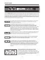
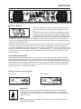
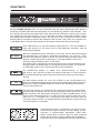
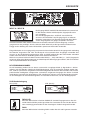
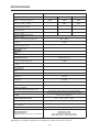
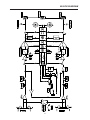
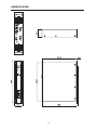
OWNER‘S MANUAL
BEDIENUNGSANLEITUNG
CP 1200
PRECISION SERIES
CONTENTS
IMPORTANT SAFETY INSTRUCTIONS
IMPORTANT SERVICE INSTRUCTIONS
DESCRIPTION
UNPACKING & WARRANTY
INSTALLATION NOTES
FRONT VIEW
REAR VIEW
INPUT A / INPUT B
PARALLEL
POWER AMP OUTPUT
BRIDGED MODE
GROUND-LIFT SWITCH
MAINS INPUT
SPECIFICATIONS / TECHNISCHE DATEN
BLOCK DIAGRAM
DIMENSIONS / ABMESSUNGEN
.......................
.......................
.......................
.......................
.......................
.......................
.......................
.......................
.......................
.......................
.......................
.......................
.......................
.......................
.......................
.......................
3
3
4
5
5
6
7
7
7
8
8
8
8
20
21
22
WICHTIGE SICHERHEITSHINWEISE
WICHTIGE SERVICEHINWEISE
BESCHREIBUNG
AUSPACKEN & GARANTIE
INSTALLATIONSHINWEISE
FRONTSEITE
RÜCKSEITE
INPUT A / INPUT B
PARALLEL
ENDSTUFENAUSGÄNGE
BRIDGED MODE
GROUND-LIFT SCHALTER
NETZEINGANG
NETZBETRIEB & WÄRMEENTWICKLUNG
SPECIFICATIONS / TECHNISCHE DATEN
BLOCK DIAGRAM
DIMENSIONS / ABMESSUNGEN
.......................
.......................
.......................
.......................
.......................
.......................
.......................
.......................
.......................
.......................
.......................
.......................
.......................
.......................
.......................
.......................
.......................
13
13
14
15
15
16
17
17
17
18
18
18
18
19
20
21
22
������
2
IMPORTANT SAFETY INSTRUCTIONS
The lightning flash with arrowhead symbol, within an
equilateral triangle is intended to alert the user to the
presence of uninsulated „dangerous voltage“ within
the product’s enclosure that may be of sufficient
magnitude to constitute a risk of electric shock to
persons
1.
2.
3.
4.
5.
6.
7.
8.
9.
10.
11.
The exclamation point within an equilateral
triangle is intended to alert the user to
the presence of important operating and
maintance (servicing) instructions in the
literature accompanying the appliance.
Read these instructions.
Keep these instructions.
Heed all warnings.
Follow all instructions.
Do not use this apparatus near water. Do not expose this apparatus to dripping or splahing and
ensure that no objects filled with liquids, such as vases, are placed on this apparatus.
Clean only with a dry cloth.
Do not block any of the ventilation openings. Install in accordance with the anufactures instructions.
Do not install near any heat sources such as radiators, heat registers, stoves, or other apparatus
(including amplifiers) that produce heat.
Only use attachments/accessories specified by the manufacturer.
Refer all servicing to qualified service personnel. Servicing is required when the apparatus has been
damaged in any way, such as power-supply cord or plug is damaged, liquid has been spilled or
objects have fallen into the apparatus, the apparatus has been exposed to rain or moisture, does not
operate normally, or has been dropped
To completely disconnect mains power from this apparatus, the power supply cord must be
unplugged.
For US and CANADA only:
Do not defeat the safety purpose of the grounding-type plug. A grounding type plug has two blades and a third
grounding prong. The wide blade or the third prong are provided for your safety. When the provided plug does not
fit into your outlet, consult an electrican for replacement of the absolete outlet.
IMPORTANT SERVICE INSTRUCTIONS
CAUTION:
1.
2.
3.
4.
5.
6.
7.
8.
These servicing instructions are for use by qualified personnel only. To reduce
the risk of electric shock, do not perform any servicing other than that ontained
in the Operating Instructions unless you are qualified to do so. Refer all servicing
to qualified service personnel.
Security regulations as stated in the EN 60065 (VDE 0860 / IEC 65) and the CSA E65 - 94 have to
be obeyed when servicing the appliance
Use of a mains separator transformer is mandatory during maintenance while the appliance is
opened, needs to be operated and is connected to the mains
Switch off the power before retrofitting any extensions, changing the mains voltage or the output voltage.
The minimum distance between parts carrying mains voltage and any accessible metal piece (metal
enclosure), respectively between the mains poles has to be 3 mm and needs to be minded at all times.
The minimum distance between parts carrying mains voltage and any switches or breakers that are not
connected to the mains (secondary parts) has to be 6 mm and needs to be minded at all times.
Replacing special components that are marked in the circuit diagram using the security symbol (Note) is
only rmissible when using original parts.
Altering the circuitry without prior consent or advice is not legitimate.
Any work security regulations that are applicable at the location where the appliance is being serviced
have to be strictly obeyed. This applies also to any regulations about the work place itself.
All instructions concerning the handling of MOS - circuits have to be observed.
NOTE:
SAFETY COMPONENT ( MUST BE REPLACED BY ORIGINAL PART )
3
DESCRIPTION
Congratulations! With buying a Electro-Voice CP-SERIES power amplifier you have chosen an appliance that employs most advanced technology.
CP-Series power amps combine outstanding audio performance, highest reliability and operational
safety.
The audio performance of CP 1200 power amp is simply extraordinary. Optimised power supply units
employing low-leakage toroidal transformers provide extensive headroom far above the stated nominal
output. At the same time this contributes to a reduction in weight and power dissipation.
The CP 1200 is designed in Class-AB technology, have been designed to fulfil even the most demanding
requirements of touring applications. The CP 1200 amp is protected against thermal and electrical
overload, short circuit and the occurrence of HF/DC at the outputs. Back-EMF-Protection eliminates
the risk of the output transistors being damaged by electrical energy back-feed. The power outputs are
switched via relay with a time delay during soft-start. An inrush current limiter prevents mains fuses from
blowing.
Mechanical construction and workmanship also comply with the highest precision manufacturing
standards. The rigid sheet steel chassis even resists the most wearing tour operation. Two three-speed
high performance fans (off/slow/fast) guarantee outstanding thermal stability at absolute low running
noise. The ventilation is directed front-to-rear allowing trouble-free operation even in smaller amp-racks.
The electronically balanced inputs are carried out via XLR-type connectors (female). Direct-Outs for
through connecting the audio signal are also provided via XLR-type connectors (male). Input routing
allows selecting DUAL (stereo) or PARALLEL (mono) operation mode. By means of the separate
BRIDGED OUT-connector and a Bridged Mode-switch, switching to „Mono Bridged”-operation is truly
uncomplicated as well.
The recessed mounted dB-scaled level controls ensure reliable protection against mechanical damage.
These particularly precise, secure to operate detent-potentiometers are located on the front panel.
The easily readable LED display provides a quick overview of the power amp’s current operational
status. The power outputs CHANNEL A, CHANNEL B and BRIDGED OUT are carried out as extremely
durable SPEAKON-type connectors. Also located on the rear panel is a Ground-lift switch, which helps
eliminating ground-noise loops by separating the power amp’s enclosure from circuit ground. In normal
operation, the CP 1200 power amp is capable of driving loads as low as 2ohms. In Mono-Bridged mode
the allowable minimum load is 4ohms.
CP-Series power amps provide the opportunity for retrofitting an internal analogue signal processor
board with x-over and filter functions.
This owner’s manual outlines and explains several other features of your CP 1200 power amplifier.
Please, make sure to carefully read all of it and mind the instructions.
4
DESCRIPTION
UNPACKING & WARRANTY
Carefully open the packaging and take out the power amplifier. Next to the power amplifier itself, the
package also includes this owner’s manual, a mains cord and the warranty certificate. Keep the original
invoice, which states the purchase/delivery date together with the warranty certificate at a safe place.
INSTALLATION NOTES
Generally, installing or mounting power amps should be carried out in a way that guarantees continuously unopposed front-to-rear air circulation. Installation of appliances with opposite air circulation within
one cabinet or closed rack shelf system is not recommended. When including an appliance in a closed
cabinet or rack shelf system make sure to provide sufficient ventilation. Leave a gap of at least 60mm
x 330mm (up to the cabinet’s top ventilation louvers) for air circulation between the rear of the power
amplifier and the cabinet’s/rack’s rear inner wall. Make sure to leave at least 100mm of space above the
cabinet or rack shelf system. Since temperatures inside of the cabinet or rack shelf system can easily
rise up to 40°C during operation, bearing in mind the maximally allowable environmental temperature
during operation for all other appliances installed in the same rack shelf system is mandatory (also refer
to “MAINS OPERATION AND RESULTING TEMPERATURE”).
Caution: For trouble-free operation exceeding the maximally allowable environmental temperature of +40°C is not permissible.
The use of installation rails or optionally available “rear-rack-mount” rails is strongly recommended when
installing the appliance in a rack shelf system or cabinet to prevent the front panel from bending.
The power amplifier has to be protected against: dripping or splashing water, direct sunlight, high temperatures or direct influence of heat sources, high humidity, extensive dust and vibrations.
Condensation on internal parts may occur when transporting the power amplifier from a cold into a
warmer environment. In that case operation is only permissible after the appliance has gained the
new temperature (after approximately one hour). If foreign objects or liquids have entered the power
amplifier’s enclosure make sure to instantly separate the appliance from the mains power and contact
an authorised service centre for inspection before continuing operation.
5
FRONT PANEL
Use the POWER switch, located on the front panel’s, right side to switch the appliance’s power on. The
soft-start function limits against current inrush peaks on the mains, which in addition prevents the mains
line protection switch from activating during power-on. The loudspeaker outputs are activated via relay
switching with a delay of approximately 2 seconds to efficiently attenuate eventual power-on noise. The
PROTECT LED lights during the delay time and the fans run at maximum speed. This is normal, confirming the immaculate operation of the protection circuitry.
This indicator lights when the power amplifier has been switched on. Causes for the
POWER-indicator not lighting are: the appliance is not connected to the mains
or the primary fuse is defective.
The PROTECT LED indicating that one of the internal protection circuits
against thermal overload, short-circuit, Back-EMF, HF-occurrence at the output,
etc., has been activated. The output relays interrupt the connected loads from
the power amps while input signals are interrupted as well, preventing the connected
loudspeaker systems and the power amplifiers themselves from being damaged.
Whatever caused the fault – e.g. a short-circuited speaker cable – needs to be remedied. In case of thermal overload you have to wait until the power amplifier automatically regains normal operation.
The SIGNAL LED lights as soon as an audio signal of approximately 30dB below full
modulation is present at the output. The LED is dimmed when speaker cables are
short-circuited or a protection circuit has been activated.
The 0dB LED lights whenever the power amplifier is driven at its maximum. Higher
input voltage does not result in higher peak output voltage. In addition, the 0dB
indicator comes in handy when adjusting external limiters.
This indicator lights as soon as the integrated dynamic audio signal limiter is
activated and the power amplifier is driven at the clipping limit or generally at its
maximum capacity. Short-term blinking is not a problem, because the internal limiter
controlls input levels of up to +21dBu down to a THD of approximately 1%. If, on the
other hand, this LED lights constantly, reducing the volume is recommended to
prevent the loudspeaker systems connected from being damaged by probable
overload.
Detent potentiometers scaled in dB (steps of 1dB) for
adjusting the power amp’s overall volume. To prevent
distortion in mixing consoles connected to your CP-Series
amp, setting these controls to a value between 0dB and -6dB
is generally recommended. The dB-scale provides direct
indication of the control attenuation applied to the fixed
internal amplification.
6
REAR PANEL
INPUT A / INPUT B
The inputs INPUT A & INPUT B are electronically balanced
for direct connection of mixing consoles, signal processors,
etc.
The XLR-type connectors OUTPUT A & OUTPUT B are prepared for „through-connecting“ input signals to additional external power amps. The input signal is directly routed to these
output connectors. There are no repeaters or other electronic
components within that signal path. Accordingly, input and output connectors of the corresponding
channel are interconnected in parallel, offering permanent electrical connection, without regard to the
setting of the Power-ON switch.
Although having XLR-type output connectors, some mixing console models provide unbalanced output
connection only. When using mixers with unbalanced outputs, bridging PIN1 and PIN3 of the power
amp’s input connectors or leaving PIN3 of the cable’s plugs unconnected is necessary. Otherwise, when
feeding in unbalanced audio signals via PIN3 (b, -, „cold“) and PIN2 (a, +, „hot“), strange humming and
HF-interference may occur, which very likely will damage the power amplifier and/or the connected
speaker cabinets.
NF-CONNECTION CORDS
Choosing high-quality balanced cables (two conductors for the audio signal plus separate shielding
mesh) with XLR-type connectors is recommended for LF-signal connection. Although connecting unbalanced cables to the power amplifier inputs is possible as well, using balanced cables is always preferable. A great number of today’s audio appliances employ balanced outputs. With balanced cabling,
the shield connects all metal enclosure parts and therefore efficiently eliminates the introduction of
external interference – mostly noise and hum.
XLR-type connector pin-assignment
XLR (male)
XLR (female)
PARALLEL
The input connectors of channel A and channel B are electrically connected
in parallel when the selector switch is set to PARALLEL. However, individually
controlling the volume of both channels is still possible via the corresponding level
controls A and B.
DUAL
If the selector switch is set to DUAL, the audio signals of channels A and B are
independently amplified.
7
REAR PANEL
POWER AMP OUTPUT CONNECTORS
Power amp output connection for the two channels A
(left) and B (right) is provided via SPEAKON-type output
connectors.
A plastic cover to prevent inadvertent erroneous
connection protects the BRIDGED OUT connector. Make
sure to remove the cover only when actually operating
the power amplifier in Bridged-Mode.
BRIDGED MODE
With the BRIDGED-MODE switch being engaged, using the channel A input
for audio signal feed is mandatory, since input B provides no function. While
the amplifier of channel A operates as usual, the audio signal is internally
inverted and routed to the amplifier of channel B. Both amps – A and B – now
work in push-pull operation to provide doubled output voltage at the
BRIDGED-OUT connector.
The regular output voltage of each amplifier channel A / B is still present at the
corresponding output connector CHANNEL A or CHANNEL B. However, using these signals is not recommendable because of the aforementioned phase
inversion. Operating the power amp in Bridged Mode with loads of 2ohms connected is not allowable.
CAUTION: Extremely high voltages might be present at the BRIDGED OUT connector during
Bridged-Mode operation. The connected loudspeaker systems have to be capable of handling
such high voltages. Please make sure that power handling specifications as stated in the documentation supplied with your speaker systems match the specifications of the power amplifier.
GROUND-LIFT SWITCH
The ground-lift switch allows eliminating noise loops. If the power amplifier is
operated together with other equipment in a 19“ rack-shelf, setting the switch
to its GROUNDED position is recommended. If the power amplifier is operated
together with appliances with differing ground potentials, set the switch to its
UNGROUNDED position.
MAINS INPUT
Under normal circumstances, the mains fuse only blows in case of fault.
Replacing the fuse is only permissible when using a new fuse of the same
type with identical amperage, voltage and blow characteristics. If the mains
fuse blows more often, please contact an authorized service centre.
The high-performance mains cord supplied with your power amplifier complies
to applicable safety regulations, plus that its diameter corresponds to the power amp’s power output capacity. Make sure to use the supplied mains cord for connecting the power amp
to the mains, if possible. Using mains cords with smaller diameters results in higher leakage and consequently reduced maximum power output capacity.
At 100V and 120V units the mains fuse is installed internally. This is fore safety reasons. In case of a
blown mains fuse please contact a qualified service personnel for servicing.
8
MAINS OPERATION & RESULTING TEMPERATURE
MAINS OPERATION & RESULTING TEMPERATURE
The following tables allow determining power supply and cabling requirements.
The power drawn from the mains network is converted into output power to feed the connected
loudspeaker systems and into heat. The difference between power consumption and dispensed power
is called power dissipation (Pd). The amount of heat resulting from power dissipation might remain
inside of a rack-shelf and needs to be diverted using appropriate measures. The following table is
meant as auxiliary means for calculating temperatures inside of a rack-shelf system/cabinet and the
ventilation efforts necessary.
The column „Pd“ lists the leakage power in relation to different operational states. The column „BTU/hr“
lists the dispensed heat amount per hour.
CP 1200
idle
Max. Output Power @ 8Ω
(1)
Max. Output Power @ 4Ω
(1)
Umains
[V]
Imains
[A]
Pmains
[W]
Pout
[W]
Pd (5)
[W]
BTU/hr(1)
230V
0,37
42
-
42
143
230V
4,6
743
2 x 240
263
895
230V
7,5
1310
2 x 400
510
1740
1/3 Max. Output Power @ 4Ω
(1)
230V
4,7
774
2 x 133
508
1735
1/8 Max. Output Power @ 4Ω
(1)
230V
3,2
496
2 x 50
396
1350
1/8 Max. Output Power @ 4Ω
(2)
230V
3,0
460
2 x 50
360
1230
(2),(4)
254V
3,4
600
2 x 63
426
1455
(1)
1/8 Max. Output Power @ 4Ω
Normal Mode (-10dB) @ 4Ω
230V
3,0
450
2 x 40
370
1260
(1)
230V
6,6
1152
2 x 300
552
1885
(1)
230V
5,0
828
2 x150
528
1800
Rated Output Power (0dB) @ 4Ω
Alert (Alarm) Mode (-3dB) @ 4Ω
(1)
230V
11,6
2210
2 x 600
1010
3445
1/8 Max. Output Power @ 2Ω
(1)
230V
5,0
820
2 x 75
670
2285
1/8 Max. Output Power @ 2Ω
(2)
230V
4.7
755
2 x 75
605
2065
Max. Output Power @ 2Ω
(1) Sine Modulation (1kHz)
(2) VDE-Noise
(3) 1BTU = 1055.06J = 1055.06Ws
(4) 10% Mains Over Voltage
(5) Pd = Leakage Power
The following factors allow direct proportional calculation of the mains current Imain for different mains
supply voltages: 100V = 2.3; 120V = 1.9; 240V = 0.96
9
10
BEDIENUNGSANLEITUNG
CP 1200
PRECISION SERIES
INHALT
WICHTIGE SICHERHEITSHINWEISE
WICHTIGE SERVICEHINWEISE
BESCHREIBUNG
AUSPACKEN & GARANTIE
INSTALLATIONSHINWEISE
FRONTSEITE
RÜCKSEITE
INPUT A / INPUT B
PARALLEL
ENDSTUFENAUSGÄNGE
BRIDGED MODE
GROUND-LIFT SCHALTER
NETZEINGANG
NETZBETRIEB & WÄRMEENTWICKLUNG
SPECIFICATIONS / TECHNISCHE DATEN
BLOCK DIAGRAM
DIMENSIONS / ABMESSUNGEN
12
.......................
.......................
.......................
.......................
.......................
.......................
.......................
.......................
.......................
.......................
.......................
.......................
.......................
.......................
.......................
.......................
.......................
13
13
14
15
15
16
17
17
17
18
18
18
18
19
30
31
32
WICHTIGE SICHERHEITSHINWEISE
Das Blitzsymbol innerhalb eines gleichseitigen Dreiecks soll den Anwender auf nicht isolierte Leitungen
und Kontakte im Geräteinneren hinweisen, an denen
hohe Spannungen anliegen, die im Fall einer
Berührung zu lebensgefährlichen Stromschlägen
führen können.
Das Ausrufezeichen innerhalb eines gleichseitigen
Dreiecks soll den Anwender auf wichtige Bedienungssowie Servicehinweise in der zum Gerät gehörenden Literatur aufmerksam machen.
1.
2.
3.
4.
5.
Lesen Sie diese Hinweise.
Heben Sie diese Hinweise auf.
Beachten Sie alle Warnungen.
Richten Sie sich nach den Anweisungen.
Betreiben Sie dieses Gerät nicht in unmittelbarer Nähe von Wasser. Stellen Sie bitte sicher, dass kein Tropf- oder
Spritzwasser ins Geräteinnere eindringen kann. Platzieren Sie keine mit Flüssigkeiten gefüllte Objekte, wie Vasen
oder Trinkgefässe, auf dem Gerät ab.
6. Verwenden Sie zum Reinigen des Gerätes ausschliesslich ein trockenes Tuch.
7. Verdecken Sie keine Lüftungsschlitze. Beachten Sie bei der Installation des Gerätes stets die entsprechenden
Hinweise des Herstellers.
8. Vermeiden Sie die Installation des Gerätes in der Nähe von Heizkörpern, Wärmespeichern, Öfen oder anderer
Wärmequellen.
9. Verwenden Sie mit dem Gerät ausschliesslich Zubehör/ Erweiterungen, die vom Hersteller hierzu vorgesehen sind.
10. Überlassen Sie sämtliche Servicearbeiten und Reparaturen einem ausgebildeten Kundendiensttechniker.
Bringen Sie das Gerät direkt zu unserem Kundendienst, wenn es beschädigt wurde oder eine Funktionsstörung zeigt.
11. Um das Gerät komplett spannungsfrei zu schalten, muss der Netzstecker gezogen werden.
WICHTIGE SERVICEHINWEISE
ACHTUNG:
Diese Servicehinweise sind ausschliesslich zur Verwendung durch qualifiziertes Servicepersonal.
Um die Gefahr eines elektrischen Schlages zu vermeiden, führen Sie keine Wartungsarbeiten durch,
die nicht in der Bedienungsanleitung beschrieben sind, ausser Sie sind hierfür qualifiziert. Überlassen
Sie sämtliche Servicearbeiten und Reparaturen einem ausgebildeten Kundendiensttechniker.
1. Bei Reparaturarbeiten im Gerät sind die Sicherheitsbestimmungen nach EN 60065 ( VDE 0860 ) einzuhalten.
2. Bei allen Arbeiten, bei denen das geöffnete Gerät mit Netzspannung verbunden ist und betrieben wird, ist ein Netz Trenntransformator zu verwenden.
3. Vor einem Umbau mit Nachrüstsätzen, Umschaltung der Netzspannung oder sonstigen Modifikationen ist das Gerät
stromlos zu schalten.
4. Die Mindestabstände zwischen netzspannungsführenden Teilen und berührbaren Metallteilen
(Metallgehäuse) bzw. zwischen den Netzpolen betragen 3 mm und sind unbedingt einzuhalten.
Die Mindestabstände zwischen netzspannungsführenden Teilen und Schaltungsteilen, die nicht mit dem Netz
verbunden sind (sekundär), betragen 6mm und sind unbedingt einzuhalten.
5. Spezielle Bauteile, die im Stromlaufplan mit dem Sicherheitssymbol gekennzeichnet sind, (Note) dürfen nur durch
Originalteile ersetzt werden.
6. Eigenmächtige Schaltungsänderungen dürfen nicht vorgenommen werden.
7. Die am Reparaturort gültigen Schutzbestimmungen der Berufsgenossenschaften sind einzuhalten. Hierzu gehört
auch die Beschaffenheit des Arbeitsplatzes.
8. Die Vorschriften im Umgang mit MOS - Bauteilen sind zu beachten.
NOTE:
SAFETY COMPONENT ( MUST BE REPLACED BY ORIGINAL PART )
13
BESCHREIBUNG
Herzlichen Glückwunsch! Sie haben sich mit einer Endstufe der CP-SERIE von Electro-Voice für ein
Gerät modernster Technologie entschieden.
Die Endstufen der CP-Serie vereinen überragende Audio-Performance mit höchster Zuverlässigkeit und
Betriebssicherheit.
Die Übertragungseigenschaften der CP 1200-Endstufe sind hervorragend. Durch optimierte Netzteile
mit streuarmen Ringkerntransformatoren wird ein großer Headroom weit oberhalb der ausgewiesenen
Nennleistung erzielt und gleichzeitig eine deutliche Reduzierung des Gewichts erreicht.
Die CP 1200 ist in Class AB Technik aufgebaut und erfüllt auch die extremen Anforderungen
des harten Tour-Betriebs. Sie ist gegen Überhitzung, Überlast, Kurzschluß sowie Hochfrequenz
und Gleichspannung am Ausgang geschützt. Eine Beschädigung der Endtransistoren durch
Rückeinspeisung elektrischer Energie wird durch die Back-EMF Schutzschaltung verhindert. Beim
Softstart werden die Leistungsausgänge über Relais verzögert zugeschaltet. Zusätzlich verhindert eine
Einschaltstrombegrenzung das Ansprechen von Netzsicherungen.
Höchste Präzision ist auch in der mechanischen Konstruktion und Verarbeitung gewährleistet. Das
robuste Stahlblech-Chassis ist besonders verwindungssteif und speziell auf die Belastungen des harten
Tourbetriebs ausgelegt. Die thermische Stabilität wird durch zwei 3-Stufen Lüfter (off/slow/fast) mit sehr
niedrigem Geräuschpegel gewährleistet. Die Front-to-Rear Luftführung, erlaubt den Betrieb auch in
großen und schmalen Endstufen-Racks. Die Eingänge sind elektronisch-symmetrisch auf XLR-Buchsen
geführt. Direct-Outs zum Durchschleifen des Signals sind ebenfalls in Form von XLR-Buchsen (male)
praktischer Standard. Über das Input Routing können die Betriebsarten DUAL (Stereo) oder PARALLEL
(Mono) gewählt werden. Außerdem ist der „Mono Bridged“ –Betrieb über die separate BRIDGED OUT
Buchse und den Bridged Mode Umschalter sehr einfach zu realisieren.
Auf der Frontblende sitzen die in dB skalierten Levelregler, die als besonders präzise, bediensichere
Rastpotis ausgeführt, und zum Schutz vor mechanischer Beschädigung in der Frontblende versenkt
sind. Eine schnelle Übersicht über den aktuellen Betriebszustand der Endstufen vermittelt das leicht
ablesbare LED-Display. Die Leistungsausgänge CHANNEL A, CHANNEL B und BRIDGED OUT sind
als extrem zuverlässige SPEAKON-Buchsen ausgeführt. Ebenfalls auf der Rückwand befinden sich ein
Groundlift-Schalter, der bei Bedarf das Gehäuse der Endstufe von der Schaltungsmasse trennt und
somit Brummschleifen verhindern hilft. Die CP 1200 Endstufe kann im Normalbetrieb an Lasten bis
hinab zu 2 Ohm und im Brückenbetrieb bis zu minimal 4 Ohm eingesetzt werden.
Die CP-Serie bietet intern die Möglichkeit zur Nachrüstung einer analogen Signalprozessorkarte mit
Frequenzweichen- und Filterfunktionen.
Mit dieser Bedienungsanleitung werden Sie noch viele weitere Eigenschaften der CP 1200 Endstufe
kennenlernen. Lesen Sie deshalb bitte aufmerksam weiter.
14
BESCHREIBUNG
AUSPACKEN & GARANTIE
Öffnen Sie die Verpackung und entnehmen Sie die Endstufe. Zusätzlich zu dieser Bedienungsanleitung
liegen dem Gerät ein Netzkabel, und die Garantiekarte bei. Bewahren Sie zur Garantiekarte auch den
Kaufbeleg, der den Termin der Übergabe festlegt, auf.
INSTALLATIONSHINWEISE
Generell sind die Endstufen so aufzustellen oder zu montieren, dass die Luftzufuhr an der Frontseite
und die Entlüftung an der Geräterückseite nicht behindert wird. Die Belüftungsrichtung ist also „Frontto-Rear“. Geräte mit umgekehrter Luftführung sollen möglichst nicht im gleichen Rack/Schrank verbaut
werden. Für den Einbau in Gehäuse und Gestellschränke ist zu beachten, dass eine ausreichende
Belüftung der Geräte möglich ist. Zwischen der Endstufen Rückseite und der Schrank/Rack-Innenseite
ist ein freier Luftkanal bis zur oberen Rack- oder Schrankentlüftung von mindestens 60mm x 330mm
vorzusehen. Oberhalb des Schrankes soll ein freier Raum von mindestens 100mm für die Entlüftung zur
Verfügung stehen. Da beim Betrieb die Temperatur im Gehäuse- oder Schrank bis zu 40°C ansteigen
kann, muss die maximal zulässige Umgebungstemperatur der übrigen im Gestellschrank befindlichen
Geräte beachtet werden (siehe auch Kapitel: NETZBETRIEB UND WÄRMEENTWICKLUNG ).
Achtung: Die max. Umgebungstemperatur von +40°C soll für störungsfreien Betrieb nicht
überschritten werden.
Beim Einbau in Gestellschränken oder Transportracks, sollen in jedem Fall handelsübliche Einbauschienen oder die optional erhältlichen „Rear-rackmount“ Schienen verwendet werden, um ein Verwinden
der Frontblende zu verhindern.
Die Endstufe ist zu schützen vor: Tropf- oder Spritzwasser, direkter Sonnenbestrahlung, hoher
Umgebungstemperatur oder unmittelbarer Einwirkung von Wärmequellen, hoher Luftfeuchtigkeit,
starken Staubablagerungen und starken Vibrationen.
Können die angeführten Forderungen nicht dauerhaft gewährleistet werden, so ist eine regelmäßige
Wartung der Endstufe zwingend erforderlich, um etwaigen Ausfällen vorzubeugen.
Wenn die Endstufe direkt von einem kalten an einen warmen Ort gebracht wird, kann sich Feuchtigkeit
auf Innenteilen niederschlagen. Das Gerät darf erst in Betrieb genommen werden, wenn es sich auf die
geänderte Temperatur erwärmt hat (nach etwa einer Stunde). Sollte ein fester Gegenstand oder Flüssigkeit in das Gehäuse gelangen, trennen Sie sofort das Gerät vom Netz und lassen Sie das Gerät von
einer autorisierten Servicestelle überprüfen, bevor Sie es weiterverwenden.
15
FRONTSEITE
Mit dem POWER Schalter rechts auf der Frontblende wird das Gerät eingeschaltet. Eine SoftstartSchaltung vermeidet dabei Einschaltstromspitzen auf der Netzleitung. Dadurch wird verhindert, dass
der Leitungsschutzschalter des Stromnetzes beim Einschalten der Endstufe anspricht. Die Lautsprecher werden über die Ausgangsrelais um ca. 2 Sekunden verzögert zugeschaltet, wodurch etwaige
Einschaltgeräusche effektiv unterdrückt werden, die ansonsten in den Lautsprechern hörbar wären.
Während dieser Verzögerung leuchtet die PROTECT LED und die Lüfter laufen mit maximaler Geschwindigkeit. Dies ist normal und bestätigt die einwandfreie Funktion der Schutzschaltungen.
Diese LED leuchtet auf, wenn die Endstufe eingeschaltet ist. Falls die POWER Anzeige nicht leuchtet, ist das Gerät nicht mit dem Stromnetz verbunden, oder die
Primärsicherung defekt.
Wenn die PROTECT-Anzeige aufleuchtet, hat eine der internen Schutzschaltungen
wie Übertemperatur, Kurzschluss, Back-EMF, Hochfrequenz am Ausgang.... angesprochen. Die Endstufen werden in diesem Fall über die Ausgangsrelais von der Last
getrennt, und die Signalzufuhr unterbrochen um etwaige Schäden an den Lautsprechern oder der Endstufe selbst zu verhindern.
Die Fehlerursache, beispielsweise eine kurzgeschlossene Lautsprecherleitung muss
beseitigt werden. Bei Überhitzung muss einige Zeit gewartet werden, bis die Endstufe selbständig wieder in den normalen Betriebszustand zurückkehrt.
Die SIGNAL-LED beginnt ca. 30dB unter Vollaussteuerung zu leuchten
und zeigt an, dass generell ein Signal am Ausgang vorhanden ist. Bei Kurzschluss
von Lautsprecherleitungen oder Ansprechen einer Schutzschaltung verlischt diese
Anzeige.
Die 0dB Anzeige leuchtet auf, wenn die Endstufe an der Aussteuergrenze betrieben wird. Eine höhere Eingangsspannung hat keine Erhöhung der Spitzenausgangsspannung zur Folge. Die 0dB Anzeige kann auch bei der Einstellung von externen
Limitern sehr hilfreich sein.
Diese Anzeige leuchtet auf, sobald einer der eingebauten dynamische Audio-Limiter
anspricht und die Endstufe über der Aussteuerungsgrenze oder generell im Grenzbereich betrieben wird. Kurzzeitiges Aufleuchten ist dabei unproblematisch, da der
interne Limiter Eingangspegel bis zu +21dBu auf einen akustisch unkritischen Klirrfaktor von ca. 1% ausregeln kann. Leuchtet diese LED jedoch dauerhaft, sollte die
Lautstärke reduziert werden, um etwaige Überlastungsschäden der angeschlossenen
Lautsprecherboxen zu vermeiden.
In dB-skalierte Rastpotis ( 1 dB Schritte ) zur Anpassung der
Gesamtverstärkung der Endstufe. Zur Vermeidung von Verzerrungen in vorgeschalteten Mischpulten sollten diese
Regler normalerweise zwischen 0dB und -6dB eingestellt
werden. Die Beschriftung zeigt unmittelbar die Reglerdämpfung mit der die intern festgelegte Verstärkung verändert wird.
16
RÜCKSEITE
INPUT A / INPUT B
Die Eingänge INPUT A & INPUT B sind elektronisch symmetrisch
für den direkten Betrieb mit Mischpulten, Signalprozessoren
usw. ausgelegt.
Die XLR-Ausgangsbuchsen OUTPUT A & OUTPUT B
sind zum „Durchschleifen“ des Eingangssignals zu weiteren
Endstufen vorgesehen. Das Eingangssignal wird dabei direkt
auf die Ausgangsbuchsen gelegt, es befinden sich keine
Zwischenverstärker oder andere elektronischen Bauteile in diesem Pfad. Die Eingangs- und Ausgangsbuchsen des jeweiligen Kanals sind also direkt elektrisch parallel geschaltet und damit unabhängig von der Stellung des Power-ON-Schalters permanent miteinander verbunden.
Einige Mischpulte sind ausgangsseitig unsymmetrisch beschaltet obwohl als Ausgangssteck verbindung
XLR Stecker vorgesehen sind. Falls ein Mischpult mit unsymmetrischen Ausgängen verwendet wird,
müssen an den Endstufeneingangsbuchsen PIN1 und PIN3 miteinander über eine Brücke verbunden
werden, oder der PIN3 am Verbindungskabel muß unbeschaltet bleiben.
Wird aus unsymmetrisch beschalteten Geräten über PIN3 (b, -, „kalt“) und PIN2 (a, +, „heiß“) eingespeist,
so können eigenartige Brummstörungen und hochfrequente Schwingungen auftreten, die zu Endstufenund Lautsprecherdefekten führen können.
NF-VERBINDUNGSKABEL
Als NF-Verbindung wählen Sie am besten symmetrisch ausgelegte Kabel (2 Signaladern + Schirmgeflecht) mit XLR-Stecker. Obwohl alle Endstufeneingänge auch unsymmetrisch beleget werden können, stellt ein symmetrisch ausgeführtes NF-Verbindungskabel die bessere Alternative dar. Die meisten
professionellen Audiogeräte verfügen über symmetrisch aufgebaute Ausgänge. Der Schirm im Kabel
verbindet bei symmetrischer Signalführung alle metallischen Gehäuse und verhindert dadurch lückenlos ein Einkoppeln von externen Störsignalen, im wesentlichen Brummen, auf den Audiosignalpfad.
XLR-Steckerbelegung
XLR (male)
XLR (female)
PARALLEL
Steht der Wahlschalter in Position PARALLEL sind die Eingangsbuchsen Kanal A
und B elektrisch direkt parallel geschaltet. Die Lautstärke für Kanal A oder B kann
aber unabhängig voneinander mit den Levelreglern A oder B eingestellt werden.
DUAL
Steht der Wahlschalter in Stellung DUAL werden Kanal A und B getrennt verstärkt.
17
RÜCKSEITE
ENDSTUFENAUSGANGSBUCHSEN
Für die Endstufenkanäle A (Links) und B (Rechts) sind
jeweils SPEAKON Ausgangsbuchsen vorhanden.
Die BRIDGED OUT Buchse für den Brückenbetrieb
ist mit einem Kunststoffdeckel geschlossen, um
Anschlußfehler zu vermeiden. Entfernen Sie den Deckel
nur, wenn Sie die Endstufe tatsächlich im Brückenbetrieb
verwenden wollen.
BRIDGED MODE
Ist der Schalter BRIDGED-MODE gedrückt muß in den Kanal A eingespeist
werden. Der Input B hat dann keine Funktion.Die Endstufe im Kanal A wird
ganz normal angesteuert. Zusätzlich wird das Signal intern invertiert und
auf die Endstufe im Kanal B gelegt. Die Endstufen A und B arbeiten dann im
Gegentakt mit verdoppelter Ausgangsspannung auf die Ausgangsbuchse
BRIDGED-OUT.
Die Ausgangsspannung jeder einzelnen Endstufe A+B steht zwar noch an den
Ausgangsbuchsen CHANNEL A und CHANNEL B, soll aber wegen der Phasendrehung nicht weiter benutzt werden.
Der Betrieb von 2 Ohm Lasten ist im Bridged Mode nicht zulässig.
ACHTUNG: Im Bridged-Betrieb können sehr hohe Spannungen am BRIDGED OUT Ausgang
produziert werden. Die angeschlossenen Lautsprecher müssen für derart hohe Spannungen
ausgelegt sein. Beachten Sie unbedingt die Leistungsangaben im Datenblatt des jeweiligen
Lautsprechers und vergleichen Sie diese mit der entsprechenden Ausgangsleistung der Endstufe.
GROUND-LIFT SCHALTER
Mit dem Groundlift-Schalter können Sie Brummschleifen verhindern. Wenn
die Endstufe zusammen mit anderen Geräten in einem 19“-Rack betrieben
wird, sollte der Schalter in Stellung GROUNDED stehen. Wird die Endstufe
mit Geräten mit unterschiedlichem Erdungspotenzial betrieben, sollte der
Schalter in Stellung UNGROUNDED stehen.
NETZEINGANG
Die Netzsicherung löst unter normalen Umständen nur bei einem Fehlerfall
aus. Die Sicherung darf nur gegen eine gleichwertige Sicherung mit
gleicher Strom-, Spannungs- und Auslösecharakteristik getauscht werden.
Sollte die Netzsicherung wiederholt durchbrennen, kontaktieren Sie bitte die
nächstgelegene Servicestelle.
Die Endstufe wird mit einem qualitativ hochwertigen Netzkabel ausgeliefert,
das über ausreichend hohen Leiterquerschnitt verfügt und den sicherheitstechnischen Anforderungen genügt. Verwenden Sie möglichst nur dieses Kabel zum Anschluß der Endstufe ans Netz. Kabel mit dünneren Querschnitten haben erhöhte Verluste und entsprechend geringere
maximale Ausgangsleistung zur Folge.
18
NETZBETRIEB & WÄRMEENTWICKLUNG
NETZBETRIEB & WÄRMEENTWICKLUNG IN DER ENDSTUFE
Mit Hilfe der folgenden Tabellen können die Anforderungen für Stromversorgung und Zuleitungen
bestimmt werden.
Die vom Stromnetz aufgenommene Leistung wird in Ausgangsleistung für die Lautsprecher und in
Wärme umgewandelt. Die Differenz aus aufgenommener Leistung und abgegebener Leistung nennt
man Verlustleistung (Pd). Die durch Verluste entstehende Wärme verbleibt u.U. im Rack und muss durch geeignete Massnahmen abgeleitet werden.Zur Berechnung der Wärmeverhältnisse im Rack/Schrank bzw.zur
Dimensionierung eventuell benötigter Abluftmassnahmen kann die nachfolgende Tabelle benutzt werden.
Die Spalte Pd zeigt die Verlustleistung bei verschiedenen Betriebszuständen. Die Spalte BTU/hr
zeigt die abgegebene Wärmemenge je Stunde.
CP1200
idle
Max. Output Power @ 8Ω
(1)
Max. Output Power @ 4Ω
(1)
Umains
[V]
Imains
[A]
Pmains
[W]
Pout
[W]
Pd (5)
[W]
BTU/hr(1)
230V
0,37
42
-
42
143
230V
4,6
743
2 x 240
263
895
230V
7,5
1310
2 x 400
510
1740
1/3 Max. Output Power @ 4Ω
(1)
230V
4,7
774
2 x 133
508
1735
1/8 Max. Output Power @ 4Ω
(1)
230V
3,2
496
2 x 50
396
1350
1/8 Max. Output Power @ 4Ω
(2)
230V
3,0
460
2 x 50
360
1230
(2),(4)
254V
3,4
600
2 x 63
426
1455
(1)
230V
3,0
450
2 x 40
370
1260
(1)
230V
6,6
1152
2 x 300
552
1885
(1)
230V
5,0
828
2 x150
528
1800
1/8 Max. Output Power @ 4Ω
Normal Mode (-10dB) @ 4Ω
Rated Output Power (0dB) @ 4Ω
Alert (Alarm) Mode (-3dB) @ 4Ω
(1)
230V
11,6
2210
2 x 600
1010
3445
1/8 Max. Output Power @ 2Ω
(1)
230V
5,0
820
2 x 75
670
2285
1/8 Max. Output Power @ 2Ω
(2)
230V
4.7
755
2 x 75
605
2065
Max. Output Power @ 2Ω
(1) Sinusaussteuerung (1kHz)
(2) VDE-Rauschen
(4) 10% Netzüberspannung
(5) Pd = Verlustleistung
(3) 1BTU = 1055.06J = 1055.06Ws
Die Stromaufnahmen für andere Netze können mit folgenden Faktoren direkt proportional
umgerechnet werden: 100V = 2.3; 120V = 1.9; 240V = 0.96
19
SPECIFICATIONS
- Amplifier at rated conditions, both channels driven, 8Ω loads, unless otherwise specified.
CP 1200
Load Impedance
Maximum Midband Output Power
THD = 1%, 1kHz, Dual Channel
Rated Output Power
THD < 0.1%, 20Hz ... 20kHz
Max. Single Channel Output Power
Dynamic-Headroom, IHF-A
Max. Single Channel Output Power
Continuous, 1kHz
Max. Bridged Output Power
THD = 1%, 1kHz
Maximum RMS Voltage Swing
THD = 1%, 1kHz
Power Bandwith
THD = 1%, ref. 1kHz, half power @ 4Ω
2Ω
4Ω
8Ω
600W
400W
240W
--
300W
150W
1100W
580W
300W
800W
480W
270W
--
1200W
800W
50V
10Hz ... 60kHz
Voltage Gain
ref. 1kHz
Input Sensitivity
rated power @ 8Ω , 1kHz
THD at rated output power,
MBW = 80kHz, 1kHz
IMD-SMPTE
60Hz, 7kHz
DIM30
3.15kHz, 15kHz
32,0 dB
+1.15 dBu (0.88 V rms)
< 0.05%
< 0.02%
< 0.01%
Maximum Input Level
+22dBu (9.76 Vrms)
Crosstalk
ref. 1kHz, at rated output power
Frequency Response
ref. 1kHz
Input Impedance
active balanced
Damping Factor
1kHz
< - 80dB
15Hz ... 40kHz ( ±1dB)
20kΩ
> 300
Slew Rate
25 V/ms
Signal to Noise Ratio, Amplifier
A-weighted
Output Noise
A-weighted
103.5 dB
< -70 dBu
Output Stage Topology
Power Requirements
Class AB
240, 230, 220, 120V or 100V; 50Hz ... 60 Hz (factory configured)
Power Consumption
1/8 maximum output power @ 4Ω, +10%
Protection
600W
Audio limiters, High temperature, DC, HF, Back-EMF,
Peak current limiters, Inrush current limiters, Turn-on delay
Cooling
Front-to rear, 3-stage-fans
Ambient Temperature Limits
+5°C ... +40°C ( 40°F ... 105°F)
Safety Class
I
Dimensions
(W x H x D), mm
483 x 88,1 x 386,8
Weight
13.5 kg (30.8 Ibs)
Optional:
Rear-rackmount 15,5“
Rear-rackmount 18“
2-Way Crossover, internal filter-card, 24dB, LR
(NRS 90262) 112930
(NRS 90264) 112933
330Hz (NRS 90249), 500Hz (NRS 90250)
800Hz (NRS 90251), 1200Hz (NRS 90252)
- Depending on the ambient temperature, the unit might not operate continuously at 2Ω load.
20
BLOCK DIAGRAM
21
ABMESSUNGEN
22
NOTES
23
USA
Telex Communications Inc., 12000 Portland Ave. South, Burnsville, MN 55337, Phone: +1 952-884-4051, FAX: +1 952-884-0043
Germany
EVI AUDIO GmbH, Hirschberger Ring 45, D 94315, Straubing, Germany Phone: 49 9421-706 0, FAX: 49 9421-706 265
Subject to change without prior notice.
Printed in Germany
www.dynacord.de
24
10/09/2003 / 363 493