1
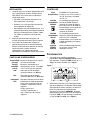
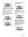
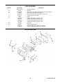
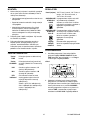
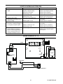
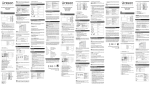
Model No. 741-TF, 741-TCE &
741-TGB 2, 4, 8 & 12
Channel Series (Merlin II)
Operating
Instructions
Single Function Timers
Prince Castle’s second generation of Merlin Timers
feature a new slim design which gives you mounting
flexibility. The 740 Series Timers are designed so
each channel can be programmed independently, and
used simultaneously. The timers are simple to
program and simple to use. The push of a button
activates each channel, and a alarm and multi-colored
flashing channel buttons alert the operator when
timing is complete.
741-Series
230 Volts
50 – 60 Hz
2
2
2
2
4
4
5
5
6
6
7
12
17
22
27
LIMITED WARRANTY
Channel Series
Electrical
TABLE OF CONTENTS
Installation . . . . . . . . . . . . . . . . . . . . . . . . . . . . . .
Displays and Indicators . . . . . . . . . . . . . . . . . . . .
Controls . . . . . . . . . . . . . . . . . . . . . . . . . . . . . . . .
Programming . . . . . . . . . . . . . . . . . . . . . . . . . . . .
Operation . . . . . . . . . . . . . . . . . . . . . . . . . . . . . . .
Cleaning . . . . . . . . . . . . . . . . . . . . . . . . . . . . . . . .
Parts List . . . . . . . . . . . . . . . . . . . . . . . . . . . . . . . .
Exploded View . . . . . . . . . . . . . . . . . . . . . . . . . . .
Troubleshooting . . . . . . . . . . . . . . . . . . . . . . . . . .
Wiring Diagram . . . . . . . . . . . . . . . . . . . . . . . . . . .
Mode d’emploi . . . . . . . . . . . . . . . . . . . . . . . . . . . .
Betriebsanweisungen . . . . . . . . . . . . . . . . . . . . . .
Istruzioni per il funzionamento. . . . . . . . . . . . . . . .
Instrucciones de operación . . . . . . . . . . . . . . . . . .
Upute za korištenje . . . . . . . . . . . . . . . . . . . . . . . .
This product is warranted to be free from defects in
material and/or workmanship for a period of one year
from date of original installation, not to exceed 18
months from date of shipment from our factory.
Any component which proves to be faulty in material
and/or workmanship will be replaced or repaired (at the
option of Prince Castle, Inc.) without cost to the
customer for parts or labor.
This warranty is subject to the following exceptions/
conditions:
• This equipment is portable, charges for on location
service (e.g. trip charges and mileage) are not
included in the provisions of this warranty.
• Use of any non-genuine Prince Castle parts voids this
warranty. All genuine Prince Castle replacement
spare parts are warranted for ninety (90) days from
date of purchase.
• All work must be performed by an authorized Prince
Castle Service Agency. Failure to do so will void this
warranty.
• Damage caused by carelessness, neglect, and/or
abuse (e.g., dropping, tampering or altering parts),
equipment damaged in shipment, by fire, flood or an
act of God is not covered under this warranty.
PRINCE CASTLE LLC
WORLDWIDE
Printed in 2011
Prince Castle LLC
355 East Kehoe Blvd. • Carol Stream, IL 60188 USA
Telephone: 630-462-8800 • Fax : 630-462-1460
Toll Free: 1-800-PCASTLE
www.princecastle.com
741-500FGISCrevD
INSTALLATION
CONTROLS
1. After you have removed the timer from the carton,
inspect the unit for signs of damage. If there is
damage to the unit:
Channel
(Timer)
The 741-T2 has 2 channels, the
741-T4 has 4 channels, the 741-T8
has 8 channels and the 741T12 has
12 channels.
SCAN/UP
ARROW
In the program mode, it increases
time values for each channel. In the
Run Mode, it is used in conjunction
with logo button to increase the
volume.
• Notify carrier within 24 hours after delivery.
• Save carton and packing materials for
inspection purposes.
• Contact your local dealer or, if purchased
directly, the Prince Castle Customer Sales
Department at 1-800-722-7853 to arrange for a
replacement to be sent.
SCAN/DOWN In the program mode, it decreases
ARROW
time values for each channel. In the
Run Mode, it is used in conjunction
with logo button to decrease the
volume.
2. Verify that all parts have been received. Bracket
Mounting screws provided.
3. To mount the timer, place mounting brackets in
desired location. Scribe location of mounting
holes, center punch, and drill holes. Attach timer
to mounting brackets placing star washer
between bracket and timer.
PRINCE
CASTLE
Logo
PROGRAMMING
DISPLAYS AND INDICATORS
TIME
Display
Shows the channel number
selected and in use. (The 741-T2
model does not have this display.)
H:M
Indicates the time value is in Hours
and Minutes.
M:S
Indicates that the time value is in
Minutes and Seconds.
LED
Indicators
1. To program, press and hold the PRINCE
CASTLE logo for six seconds. The TIME display
changes from ---- to Prog, and a beep will sound.
See figure 1.
Shows the time for the selected
channel number.
CHANNEL
Display
figure 1
Located above each channel timer
button, these lights change color
depending on the stage of the
countdown.
Green = first 70% of countdown,
Yellow = next 20% of countdown,
Red = last 10% of countdown.
741-500FGISCrevD
Activates Program Mode and used
to adjust the alarm sound level.
2. Select and press the timer channel to be
programmed. The LED indicator for the selected
button will turn yellow and a beep will sound. The
selected channel number will be displayed in the
CHANNEL display, the current programmed time
for that channel will be displayed in the TIME
display, and the time value will indicate either
H:M OR M:S. See figure 2.
2
4. To program another channel, press the desired
channel button. Repeat programming procedures
in steps 2 and 3. See figure 5.
figure 2
figure 5
3. To change the program time for the selected
channel, use the SCAN/UP Arrow or the SCAN/
DOWN Arrow button.
IMPORTANT: To change from Minutes and Seconds
M:S to Hours and Minutes H:M. Press and hold the
SCAN/UP Button. When the display reaches 59:59 it
will automatically change to 1:00 Hour and the LED
will switch from M:S to H:M. The program value for
the H:M indicator is from 1:00 hour to 17 hours: 59
minutes. See figures 3 and 4.
5. When finished programming each desired
channel, momentarily press the PRINCE
CASTLE logo to end the Program Mode. This
saves the program changes you have made for
all channels. See figure 6.
figure 6
figure 3
6. You can change the sound level of the alarm in
RUN MODE. Press and hold the PRINCE
CASTLE logo; then, within six seconds, press
either the SCAN UP Arrow button or the SCAN
DOWN Arrow button. The SCAN UP Arrow
button adjusts the sound level to the louder alarm,
and the SCAN DOWN Arrow button adjusts the
sound level to the lower alarm. See figure 7.
figure 4
figure 7
3
741-500FGISCrevD
IMPORTANT: There are three indicators that signal
the operator when the timing cycle is complete: The
CHANNEL display shows the channel associated
with the alarm. The TIME display shows End. The
LED indicator in the channel button flashes red.
OPERATION
1. Press a channel button to activate a timing
cycle. (All channels can be activated and
running at the same time.) The time channel
number with the least amount of time remaining
will be displayed in the CHANNEL display, its
time remaining will countdown in the TIME
display, and the time value M:S or H:M will be
illuminated. See figure 8.
4. When the timing cycle is complete, and the alarm
sounds, press the channel button with the
flashing red indicator to cancel the alarm. See
figure 10.
figure 10
figure 8
5. The scan feature is used to check the time values
on other active channels. There are two different
ways to scan active channels. Press the SCAN/
UP or SCAN/DOWN button or press any of the
active timer CHANNEL buttons. If no other button
is pressed within 5 seconds, the display will
change to show the timer with the least amount of
time left. See figure 11.
2. Press the desired channel button three times
within five seconds to cancel an active timing
cycle.
IMPORTANT: The channel timer button’s multicolored LED indicator shows the status of the timer.
The indicator has three colors: green, yellow, and red.
The LED will be green during the first 70% of the
countdown. It changes to yellow during the next 20%
of the countdown. It will be red during the final 10% of
the countdown, and will start flashing red once the
time has run out.
figure 11
3. The timer will countdown from the programmed
value to zero. At zero, the display flashes End
and the alarm sounds. See figure 9.
figure 9
CLEANING
1. Do not allow grease to build up on the timer, wipe
it down daily with clean damp cloth.
IMPORTANT: Do not use abrasive or chemical
cleaners on your timer, this may cause damage to the
overlay.
741-500FGISCrevD
4
PARTS LIST
Item
7
10
11
12
Part Number
88-653-2-4SA
741-021
85-101-04S
740-9S
740-225S
735-241S
70-048S
735-240S
735-211S
740-026S
735-208S
86-226
69-079S
72-200-1S
72-200-2S
15
16
17
20
24
—
—
Description
Speaker Assy.
I.C. Connector
Power Supply PCB
PCB, Main (T2)
PCB, Main (T4, T8 & T12)
Mounting Bracket Kit
Knob
Switch Panel Assy. (T2)
Switch Panel Assy. (T4)
Switch Panel Assy. (T8)
Switch Panel Assy. (T12)
Spacer
Rivet (Pkg. of 2)
Line Cord (CE) Not Shown
Line Cord (GB) Not Shown
EXPLODED VIEW
20
11
12
16
24
17
15
7
15
16
10
5
741-500FGISCrevD
TROUBLESHOOTING GUIDE
PROBLEM
CAUSE
SOLUTION
A. No displays or indicators lit.
Unit unplugged.
Store’s circuit breaker blown.
Defective transformer.
Circuit inoperable.
Plug unit in.
Reset breaker.
Replace Power Supply Board.
Replace Main Circuit Board.
B. Absence of Audio Alarm.
Speaker inoperable.
Circuit inoperable.
Replace Speaker.
Replace Main Circuit Board.
C. Unit will not enter program mode.
Display does not show “Prog”.
All channels are still counting.
Logo Switch inoperable.
Wait until channels are in stop mode.
Replace Switch Panel.
D. Unit enters program mode. Display
shows “Prog”, but cannot change
times.
The channel is still counting.
Arrow Switch inoperable.
Circuit inoperable.
Wait until channel is in stop mode.
Replace Switch Panel.
Replace Main Circuit Board.
E. Unable to start, stop, or store timer
presets in program mode. Missing
or abnormal characters in displays.
Circuit inoperable.
Replace Switch Panel. If problem
persists, replace Main Circuit Board.
WIRING DIAGRAM 741-T2
MAIN PCB
MEMBRANE SWITCH
RED
GROUND
GRN/YEL
BLUE
BROWN
POWER INLET
741-500FGISCrevD
6
BLACK
SPEAKER
POWER SUPPLY PCB
YELLOW
BLACK
SPEAKER
INSTALLATION
COMMANDES
1. Après avoir extrait le minuteur de son emballage,
vérifier qu’il est en bon état. En cas de
dommages de l’appareil:
Canal
(Minuteur)
• Notifier le transporteur dans les 24 heures qui
suivent la livraison.
Le 741-T2 comporte 2 canaux, le
741-T4 4 canaux, le 741-T8 8
canaux et le 741T12 12 canaux.
FLÈCHE
En mode Programmation, cette
SCAN/HAUT touche permet d’augmenter la
valeur de durée d’un canal. En
mode Exécution, elle s’utilise en
association avec la touche logo
pour augmenter le volume.
• Conserver le carton et les matériaux
d’emballage à des fins d’examen.
• Contacter le revendeur local ou, en cas d’achat
direct, le Service à la clientèle Prince Castle au
(+1) 800-722-7853 afin d’obtenir l’envoi d’un
appareil de rechange.
FLÈCHE
SCAN/BAS
2. Vérifier que toutes les pièces ont été reçues. Les
vis de fixation des supports sont fournies.
3. Pour poser le minuteur, placer les supports de
fixation à l’endroit souhaité. Tracer l’emplacement
des trous de fixation, marquer au pointeau et
percer. Poser les supports de fixation en plaçant
une rondelle éventail entre le support et
l’appareil.
Logo
PRINCE
CASTLE
En mode Programmation, cette
touche permet de diminuer la valeur
de durée d’un canal. En mode
Exécution, elle s’utilise en
association avec la touche logo
pour diminuer le volume.
Cette touche active le mode
Programmation et sert à régler le
niveau sonore de l’alarme.
PROGRAMMATION
ÉCRANS ET INDICATEURS
Écran
TIME
1. Pour programmer, tenir la touche logo PRINCE
CASTLE enfoncée pendant six secondes.
L’écran TIME passe de ---- à Prog et un bip
sonore est audible. Voir figure 1.
Affiche la durée pour le canal
sélectionné.
Écran
CHANNEL
Affiche le numéro de canal
sélectionné et en cours d’utilisation
(le modèle 741-T2 ne comporte pas
cet écran).
H:M
Indique que la durée est affichée en
Heures et Minutes.
M:S
Indique que la durée est affichée en
Minutes et Secondes.
Voyants
lumineux
Placés au-dessus de chaque
touche de canal, ces voyants
changent de couleur en fonction de
l’avancement du compte à rebours.
Vert = premiers 70% du compte à
rebours, Jaune = 20% suivants du
compte à rebours, Rouge = derniers
10% du compte à rebours.
figure 1
2. Appuyer sur la touche du canal minuteur à
programmer. Le voyant lumineux de la touche
sélectionnée s’allume en jaune et un bip sonore
est audible. Le numéro du canal sélectionné
s’affiche sur l’écran CHANNEL, la durée
actuellement programmée pour ce canal s’affiche
sur l’écran TIME, cette valeur s’affichant en mode
H:M OU M:S. Voir figure 2.
7
741-500FGISCrevD
figure 2
4. Pour programmer un autre canal, appuyer sur la
touche du canal souhaité. Répéter les opérations
de programmation des étapes 2 et 3. Voir figure 5.
figure 5
3. Pour changer la durée programmée du canal
sélectionnée, utiliser le touche flèche SCAN/
HAUT ou flèche SCAN/BAS.
IMPORTANT : Pour passer du mode d’affichage
Minutes et Secondes M:S à Heures et Minutes H:M,
tenir la touche SCAN/HAUT enfoncée. Lorsque la
valeur atteint 59:59, elle passe automatiquement à
1:00 heure et le voyant lumineux passe de M:S à
H:M. La valeur de durée pour le voyant H:M s’étend
de 1:00 heure à 17 heures: 59 minutes. Voir figures 3
and 4.
5. Une fois que chaque canal souhaité est
programmé, appuyer sur le logo PRINCE
CASTLE pour quitter le mode Programmation.
Ceci enregistre les modifications effectuées sur
tous les canaux. Voir figure 6.
figure 6
figure 3
6. Le niveau sonore de l’alarme peut être modifié
en MODE EXÉCUTION. Tenir la touche logo
PRINCE CASTLE enfoncée ; dans les six
secondes, appuyer sur la touche flèche SCAN
HAUT ou sur la touche flèche SCAN BAS. La
touche flèche SCAN HAUT augmente le niveau
sonore de l’alarme, la touche flèche SCAN BAS
diminue le niveau sonore de l’alarme. Voir
figure 7.
figure 4
figure 7
741-500FGISCrevD
8
IMPORTANT : Il y trois indicateurs signalant à
l’opérateur la fin de cycle du minuteur : L’écran
CHANNEL affiche le numéro de canal associé à
l’alarme. L’écran TIME affiche End. Le voyant
lumineux de la touche du canal clignote en rouge.
FONCTIONNEMENT
1. Appuyer sur un bouton de canal pour activer le
cycle de minutage correspondant (tous les
canaux peuvent être activés et s’exécuter en
même temps). L’écran CHANNEL affiche le
numéro du canal minuteur dont la durée restante
est la plus courte, l’écran TIME affiche le compte
à rebours correspondant et le voyant de valeur de
durée M:S ou H:M s’allume selon le cas. Voir
figure 8.
4. À la fin du cycle du minuteur, l’alarme sonore se
déclenche ; appuyer sur la touche de canal dont
le voyant clignote en rouge pour couper l’alarme.
Voir figure 10.
figure 10
figure 8
5. La fonction de consultation permet de vérifier les
valeurs de durée des autres canaux actifs. Il y a
deux moyens différents de consulter les canaux
actifs. Appuyer sur la touche SCAN/HAUT ou
SCAN/BAS ou sur la touche de l’un quelconque
des canaux minuteurs actifs. Si aucune autre
touche n’est enfoncée dans les 5 secondes,
l’écran revient à l’affichage du minuteur de durée
restante la plus courte. Voir figure 11.
2. Appuyer sur la touche du canal souhaité trois fois
dans les cinq secondes pour annuler un cycle de
minutage actif.
IMPORTANT : Le voyant lumineux multicolore d’une
touche de canal minuteur indique l’état du minuteur.
Ce voyant a trois couleurs : vert, jaune et rouge. Le
voyant s’affiche en vert pendant les premiers 70% du
compte à rebours. Il passe au jaune durant les 20%
suivants du compte à rebours. Il s’allume en rouge
durant les derniers 10% du compte à rebours et
clignote en rouge une fois que la durée est écoulée.
figure 11
3. Le minuteur compte à rebours depuis la valeur
programmée jusqu’à zéro. À zéro, l’écran affiche
End en clignotant et l’alarme sonore se
déclenche. Voir figure 9.
figure 9
NETTOYAGE
1. Ne pas laisser de graisse s’accumuler sur le
minuteur, l’essuyer chaque jour avec un chiffon
humide propre.
IMPORTANT : Pour éviter d’endommager le
revêtement, ne pas utiliser de détergent abrasif ou
chimique sur le minuteur.
9
741-500FGISCrevD
NOMENCLATURE DES PIÈCES
Repère
7
10
11
12
Référence
88-653-2-4SA
741-021
85-101-04S
740-9S
740-225S
735-241S
70-048S
735-240S
735-211S
740-026S
735-208S
86-226
69-079S
72-200-1S
72-200-2S
15
16
17
20
24
—
—
Description
Haut-parleur
Connecteur
Carte d’alimentation
Carte principale (T2)
Carte principale (T4, T8 et T12)
Supports de fixation
Bouton de serrage
Panneau de commande (T2)
Panneau de commande (T4)
Panneau de commande (T8)
Panneau de commande (T12)
Bague d’espacement
Rivet (paquet de 2)
Cordon d’alimentation (CE) Non représenté
Cordon d’alimentation (GB) Non représenté
VUE ÉCLATÉE
20
11
12
16
24
17
15
7
15
16
10
741-500FGISCrevD
10
GUIDE DE DÉPANNAGE
PROBLÈME
CAUSE
SOLUTION
A. Aucun écran ni voyant allumé.
Appareil débranché.
Disjoncteur ouvert.
Transformateur défectueux.
Circuit défectueux.
Brancher l’appareil.
Réarmer le disjoncteur.
Changer la carte d’alimentation.
Changer la carte principale.
B. Absence d’alarme sonore.
Haut-parleur défectueux.
Circuit défectueux.
Changer le haut-parleur.
Changer la carte principale.
C. L’appareil ne passe pas en mode
Programmation. L’écran n’affiche
pas « Prog ».
Compte à rebours en cours sur tous les Attendre que les canaux soient arrêtés.
canaux.
La touche logo ne fonctionne pas.
Changer le panneau de commande.
D. L’appareil passe en mode
Programmation. L’écran affiche
« Prog », mais impossible de
changer la durée.
Compte à rebours en cours sur le canal. Attendre que le canal soit arrêté.
Les touches fléchées ne fonctionnent
Changer le panneau de commande.
pas.
Circuit défectueux.
Changer la carte principale.
E. Impossible de démarrer, arrêter ou
enregistrer des réglages de
minuteur en mode Programmation.
Caractères manquants ou
anormaux sur les écrans.
Circuit défectueux.
Changer le panneau de commande. Si
le problème persiste, changer le circuit
principal.
SCHÉMA DE CÂBLAGE 741-T2
CARTE PPALE
CONTACT. TACTILE
ROUGE
HT-PRLR
NOIR
HT-PRLR
CARTE ALIMENTATION
JAUNE
NOIR
TERRE
VRT/JNE
BLEU
BRUN
ENTRÉE ALIMENTATION
11
741-500FGISCrevD
EINBAU
BEDIENELEMENTE
1. Nach der Entnahme des Zeitgebers aus dem
Karton muss er auf Anzeichen von Schäden
untersucht werden. Falls der Zeitgeber
beschädigt ist:
Kanal
(Zeitgeber)
• Den Spediteur innerhalb von 24 Stunden nach
der Zustellung verständigen.
SCAN/
Im Programmiermodus werden mit
Aufwärtspfeil dieser Taste die Werte für die
einzelnen Kanäle erhöht. Im RUNModus (Lauf) wird diese Taste
gemeinsam mit der Logo-Taste zum
Erhöhen der Lautstärke verwendet.
• Den Karton und das Verpackungsmaterial zu
Inspektionszwecken aufheben.
• Den örtlichen Händler verständigen, bzw. bei
Direktkauf die Prince Castle
Kundendienstabteilung unter der Rufnummer
1-800-722-7853 verständigen und die
Lieferung eines Ersatzproduktes arrangieren.
SCAN/
Im Programmiermodus werden mit
Abwärtspfeil dieser Taste die Werte für die
einzelnen Kanäle verringert. Im
RUN-Modus (Lauf) wird diese Taste
gemeinsam mit der Logo-Taste zum
Verringern der Lautstärke
verwendet.
2. Überprüfen, ob alle Teile erhalten wurden. Die
Befestigungsschrauben für die Halterung werden
mitgeliefert.
3. Zur Befestigung des Zeitgebers die
Befestigungshalterungen an der gewünschten
Stelle anbringen. Die Lage der
Befestigungslöcher anzeichnen, körnen und die
Löcher vorbohren. Den Zeitgeber an den
Befestigungshalterungen anbringen und
Sternscheiben zwischen Halterung und Zeitgeber
anbringen.
PRINCE
CASTLE
Logo
1. Zum Aufrufen der Programmierung muss die
PRINCE CASTLE Logo-Taste sechs Sekunden
lang gedrückt werden. Die Anzeige TIME (Zeit)
wechselt von ---- zu Prog, und es ertönt ein
Piepton. Siehe Abb. 1.
Anzeige TIME Zeigt die Zeit für die ausgewählte
(Zeit)
Kanalnummer.
Zeigt die ausgewählte und
verwendete Kanalnummer. (Das
Modell 741-T2 verfügt nicht über
diese Anzeige.)
H:M
Zeigt den Zeitwert in Stunden (H)
und Minuten (M) an.
M:S
Zeigt den Zeitwert in Minuten (M)
und Sekunden (S) an.
LEDAnzeigen
Befinden sich über den einzelnen
Kanal-Zeitgebertasten und ändern
je nach Stufe während des
Zeitablaufs ihre Farbe.
Abb. 1
2. Die Taste für den Zeitgeberkanal drücken, der
programmiert werden soll. Die LED-Anzeige für
die ausgewählte Taste wechselt zu Gelb und es
ertönt ein Piepton. Die ausgewählte
Kanalnummer wird in der Anzeige CHANNEL
eingeblendet; die derzeit programmierte Zeit für
diesen Kanal wird in der Anzeige TIME
eingeblendet, und der Zeitwert weist entweder
H:M ODR M:S aus. Siehe Abb. 2.
Grün = ersten 70% des Ablaufs,
Gelb = nächsten 20% des Ablaufs,
Rot = letzten 10% des Ablaufs.
741-500FGISCrevD
Aktiviert den Programmiermodus
und dient zum Einstellen der
Alarmlautstärke.
PROGRAMMIERUNG
ANZEIGEN UND KONTROLLLEUCHTEN
Anzeige
CHANNEL
(Kanal)
Das Modell 741-T2 verfügt über 2
Kanäle, das Modell 741-T4 über 4
Kanäle, das Modell 741-T8 über 8
Kanäle und das Modell 741T12
über 12 Kanäle.
12
4. Um einen anderen Kanal zu programmieren,
muss die gewünschte Kanaltaste gedrückt
werden. Die Programmierverfahren in Schritten 2
und 3 oben wiederholen. Siehe Abb. 5.
Abb. 2
Abb. 5
3. Um die Programmzeit für den ausgewählten
Kanal zu ändern, muss die Taste SCAN/
Aufwärtspfeil oder SCAN/Abwärtspfeil benutzt
werden.
5. Nach Abschluss der Progammierung für die
einzelnen Kanäle kurz die PRINCE CASTLE
Logo-Taste drücken, um den Programmiermodus
zu beenden. Dadurch werden die an allen
Kanälen vorgenommenen Programmänderungen
gespeichert. Siehe Abb. 6.
WICHTIG: Um von Minuten und Sekunden M:S zu
Stunden und Minuten H:M umzuschalten, die Taste
SCAN/Aufwärtspfeil drücken. Wenn die Anzeige
59:59 erreicht, ändert sie sich automatisch zu 1:00
Stunde und die LED wechselt von M:S zu H:M. Der
Programmwert für H:M kann zwischen 1:00 und 17
Stunden: 59 Minuten liegen. Siehe Abb. 3 und 4.
Abb. 6
Abb. 3
6. Die Lautstärke des Alarms im RUN-MODUS kann
auch geändert werden. Die PRINCE CASTLE
Logo-Taste gedrückt halten und innerhalb von
sechs Sekunden entweder die Taste SCAN/
Aufwärtspfeil oder die Taste SCAN/
Abwärtspfeil drücken. Die Taste SCAN/
Aufwärtspfeil stellt die Lautstärke der oberen
Alarms und die Taste SCAN/Abwärtspfeil die
Lautstärke des unteren Alarms ein. Siehe Abb. 7.
Abb. 4
Abb. 7
13
741-500FGISCrevD
WICHTIG: Es gibt drei Kontrollleuchten, die dem
Bediener ausweisen, wann ein Zeitgeberzyklus
abgelaufen ist: Die Anzeige CHANNEL (Kanal) zeigt
den Kanal des jeweiligen Alarms. Die Anzeige TIME
(Zeit) enthält End (Ende). Die LED-Kontrollleuchte in
der Kanaltaste blinkt rot.
BETRIEB
1. Um einen Zeitgeberzyklus zu beginnen, eine
Kanaltaste drücken. (Alle Kanäle können
gleichzeitig aktiviert werden und laufen.) Die
Zeitgeberkanalnummer, die als erstes ablaufen
wird (kürzeste verbleibende Dauer), wird auf
der Anzeige CHANNEL eingeblendet; die
verbleibende Zeitdauer läuft auf der Anzeige
TIME ab und der Zeitwert M:S oder H:M ist
beleuchtet. Siehe Abb. 8.
4. Nach Abschluss des Zeitgeberzyklus ertönt der
Alarm und es muss die Kanaltaste mit der rot
blinkenden Kontrollleuchte gedrückt werden, um
den Alarm zu quittieren. Siehe Abb. 10.
Abb. 10
Abb. 8
5. Die Scan-Funktion dient zum Prüfen der
Zeitwerte in anderen aktiven Kanälen. Aktive
Kanäle können auf zwei unterschiedliche Weisen
gescannt werden. Die Taste SCAN/Aufwärtspfeil
oder SCAN/Abwärtspfeil drücken oder eine
Taste CHANNEL (Kanal) für einen der aktiven
Zeitgeberkanäle drücken. Falls innerhalb von fünf
Sekunden keine andere Taste gedrückt wird,
wechselt die Anzeige zum Zeitgeber mit der
geringsten verbleibenden Ablaufdauer. Siehe
Abb. 11.
2. Die gewünschte Kanaltaste innerhalb von fünf
Sekunden drei Mal drücken, um einen aktiven
Zeitgeberzyklus abzubrechen.
WICHTIG: Die mehrfarbige LED-Kontrollleuchte der
Kanalzeitgebertaste zeigt den Status des Zeitgebers
an. Die Kontrollleuchte kann drei Farben haben:
Grün, Gelb und Rot. Die LED ist während der ersten
70% des Zeitablaufs grün. In den nächsten 20% des
Zeitablaufs leuchtet sie gelb auf. Während der letzten
10% des Zeitablaufs leuchtet sie rot und beginnt zu
blinken, sobald die Zeitdauer abgelaufen ist.
Abb. 11
3. Der Zeitgeber zählt vom programmierten Wert bis
auf Null herunter. Bei Null blinkt auf der Anzeige
End (Ende) und der Alarm ertönt. Siehe Abb. 9.
Abb. 9
REINIGUNG
1. Nicht zulassen, dass sich Fett auf dem Zeitgeber
ablagert. Dieses täglich mit einem feuchten Tuch
abwischen.
WICHTIG: Um Schäden an der Deckschicht zu
verhindern, keine scheuernden Reiniger oder
Chemikalien auf dem Zeitgeber anwenden.
741-500FGISCrevD
14
TEILELISTE
Pos.
7
10
11
12
Teilenummer
88-653-2-4SA
741-021
85-101-04S
740-9S
740-225S
735-241S
70-048S
735-240S
735-211S
740-026S
735-208S
86-226
69-079S
72-200-1S
72-200-2S
15
16
17
20
24
—
—
Beschreibung
Lautsprecher
Steckverbinder
Netzteil, Hauptsteuerkarte
Hauptversorgung, Hauptsteuerkarte (T2)
Hauptversorgung, Hauptsteuerkarte (T4, T8 u. T12)
Befestigungshalterung, Satz
Taste
Tastenfeld (T2)
Tastenfeld (T4)
Tastenfeld (T8)
Tastenfeld (T12)
Distanzstück
Niete (je 2 Stück)
Netzkabel (CE), nicht dargestellt
Netzkabel (GB), nicht dargestellt
EXPLOSIONSDARSTELLUNG
20
11
12
16
24
17
15
7
15
16
10
15
741-500FGISCrevD
ANLEITUNG ZUR FEHLERSUCHE
PROBLEM
URSACHE
LÖSUNG
A. Anzeige oder Kontrollleuchten nicht Einheit nicht an Stromversorgung
an.
angeschlossen.
Trennschalter ist gefallen.
Trafo ist ausgefallen.
Schaltkreis ist funktionsunfähig.
Einheit anschließen.
B. Kein akustischer Alarm.
Lautsprecher ist funktionsunfähig.
Schaltkreis ist funktionsunfähig.
Lautsprecher ersetzen.
Hauptsteuerkarte ersetzen.
C. Einheit kann nicht in den
Programmiermodus geschaltet
werden. Anzeige enthält nicht
„Prog“.
Alle Kanäle laufen noch ab.
Warten, bis die Kanäle im Stopp-Modus
sind.
Tastenfeld ersetzen.
Trennschalter zurücksetzen.
Netzversorgungskarte ersetzen.
Hauptsteuerkarte ersetzen.
Logo-Taste ist defekt.
D. Einheit ruft Programmiermodus auf. Der Kanal läuft noch ab.
Anzeige enthält „Prog“, aber
Zeitwerte können nicht geändert
Pfeiltaste ist defekt.
werden.
Schaltkreis ist funktionsunfähig.
Warten, bis der Kanal im Stopp-Modus
sind.
Tastenfeld ersetzen.
Hauptsteuerkarte ersetzen.
E. Starten, Stoppen oder Speichern
der Zeitgeberwerte im
Programmiermodus ist nicht
möglich. Fehlende oder
ungewöhnliche Zeichen auf den
Anzeigen.
Tastenfeld ersetzen. Falls sich das
Problem nicht beseitigen lässt, die
Hauptsteuerkarte ersetzen.
Schaltkreis ist funktionsunfähig.
SCHALTPLAN 741-T2
HAUPTSTEUERKARTE
MEMBRANTASTE
ROT
LAUTSPRECHER
MASSE
GRÜN/GELB
BLAU
BRAUN
NETZANSCHLUSS
741-500FGISCrevD
SCHWARZ
LAUTSPRECHER
NETZTEIL,
HAUPTSTEUERKARTE
GELB
SCHWARZ
16
INSTALLAZIONE
COMANDI
1. Dopo aver rimosso il timer dalla confezione,
ispezionare l’unità per individuare eventuali
danni. In caso di danni all’unità:
Canale
(Timer)
• Avvisare il trasportatore entro 24 ore dalla
consegna.
FRECCIA
In modalità di programmazione,
aumenta i valori temporali per
SCAN/UP
(Scansione/giù) ciascun canale. In modalità di
esecuzione, viene usato
unitamente con il pulsante del
logo per aumentare il volume.
• Conservare la confezione ed il materiale di
imballaggio in caso di ispezione.
• Rivolgersi al concessionario di zona, oppure in
caso di acquisto diretto, chiamare la linea verde
del reparto di Assistenza clienti Prince Castle al
numero 1-800-722-7853 per richiedere un
ricambio.
FRECCIA
In modalità di programmazione,
SCAN/DOWN riduce i valori temporali per
(Scansione/su) ciascun canale. In modalità di
esecuzione, viene usato
unitamente con il pulsante del
logo per ridurre il volume.
2. Controllare che tutte le parti siano state ricevute.
Le viti di montaggio piastra sono incluse.
3. Per montare il timer, posizionare le piastre di
montaggio nel punto desiderato. Tracciare la
posizione dei fori di montaggio, punzonare il
centro e praticare i fori. Fissare il timer alle piastre
di montaggio, inserendo una rondella a stella tra
la piastra ed il timer.
Logo PRINCE
CASTLE
DISPLAY ED INDICATORI
1. Per programmare, premere e tenere premuto il
logo PRINCE CASTLE per sei secondi. Il display
TIME cambia da ---- a Prog e scatta un bip.
Vedere la figura 1.
Mostra il numero di canale
selezionato ed in uso (il modello
741-T2 non dispone di questo
display).
H:M
Indica il valore temporale in Ore e
Minuti.
M:S
Indica il valore temporale in Minuti e
Secondi.
Spie
LED
Situate sopra il timer dei singoli
canali, queste spie cambiano colore
secondo il progresso del conto alla
rovescia.
Attiva la modalità di
programmazione e viene usato
per regolare il livello di allarme
sonoro.
PROGRAMMAZIONE
Display TIME Indica l’ora per il numero di canale
(Ora)
selezionato.
Display
CHANNEL
(Canale)
Il modello 741-T2 dispone di 2
canali, il modello 741-T4 di 4
canali, il modello 741-T8 di 8
canali ed il modello 741T12 di 12
canali.
figura 1
2. Selezionare e premere il canale del timer da
programmare. La spia LED per il pulsante
selezionato diventa gialla ed emette un bip. Nel
display CHANNEL (Canale) viene visualizzato il
numero di canale selezionato, nel display TIME
(Ora) viene visualizzata l’ora programmata
corrente per quel canale, mentre il valore
temporale indica H:M OPPURE M:S. Vedere la
figura 2.
Verde = primo 70% del conto alla
rovescia,
Giallo = 20% successivo del conto
alla rovescia,
Rosso = ultimo 10% del conto alla
rovescia.
17
741-500FGISCrevD
4. Per programmare un altro canale, premere il
pulsante del canale desiderato. Ripetere le
procedure di programmazione indicate nella fasi
2 e 3. Vedere la figura 5.
figura 2
figura 5
3. Per cambiare l’ora di programmazione per il
canale selezionato, usare i pulsanti a freccia
SCAN/UP (Scansione/su) o SCAN/ DOWN
(Scansione/giù).
5. Al termine della programmazione dei singoli
canali desiderati, premere temporaneamente il
logo PRINCE CASTLE per terminare la modalità
di programmazione. Questo salva le modifiche di
programmazione apportate per tutti i canali.
Vedere la figura 6.
IMPORTANTE: per cambiare da Minuti e Secondi
M:S ad Ore e Minuti H:M. Premere e tenere premuto
il pulsante SCAN/UP (Scansione/su). Quando il
display raggiunge 59:59, cambia automaticamente su
1:00 Ora e la spia LED passa da M:S a H:M. Il valore
di programmazione per l’indicatore H:M va da 1:00
ora a 17 ore: 59 minuti. Vedere le figures 3 e 4.
figura 6
figura 3
6. È possibile cambiare il livello sonoro dell’allarme
nella MODALITÀ DI ESECUZIONE. Premere e
tenere premuto il logo PRINCE CASTLE; quindi
entro sei secondi, premere il pulsante a freccia
SCAN UP (Scansione/su) o SCAN DOWN
(Scansione/giù). Il pulsante a freccia SCAN UP
(Scansione/su) aumenta il volume del livello
sonoro, mentre il pulsante a freccia SCAN
DOWN (Scansione/giù) lo riduce. Vedere la
figura 7.
figura 4
figura 7
741-500FGISCrevD
18
IMPORTANTE: vi sono tre indicatori che segnalano
all’operatore il completamento del ciclo di
temporizzazione: Il display CHANNEL mostra il
canale associato all’allarme. Il display TIME mostra
End (Fine). La spia LED nel pulsante del canale
lampeggia di colore rosso.
FUNZIONAMENTO
1. Premere il pulsante di un canale per attivare un
ciclo di temporizzazione (tutti i canali possono
essere attivati ed eseguiti contemporaneamente).
Il numero del canale temporale con un valore
temporale residuo minimo viene visualizzato nel
display CHANNEL, il tempo restante viene
indicato con conto alla rovescia nel display TIME
e viene illuminato il valore temporale M:S o H:M.
Vedere la figura 8.
4. Al completamento del ciclo di temporizzazione
scatta l’allarme; premere il pulsante del canale
con l’indicatore rosso lampeggiante per annullare
l’allarme. Vedere la figura 10.
figura 10
figura 8
5. La funzione di scansione viene usata per
controllare i valori temporali sugli altri canali attivi.
Esistono due modi per effettuare la scansione dei
canali attivi. Premere il pulsante SCAN/UP
(Scansione su) o SCAN/DOWN (Scansione/
giù) o premere uno dei pulsanti CHANNEL
(Canale) dei timer attivi. Se non si premono altri
pulsanti entro 5 secondi, il display mostra il timer
con il valore temporale residuo minimo. Vedere la
figura 11.
2. Premere tre volte il pulsante del canale
desiderato, entro cinque secondi, per annullare
un ciclo di temporizzazione attivo.
IMPORTANTE: la spia LED a più colori del pulsante
del timer del canale riporta lo stato del timer.
L’indicatore ha tre colori: verde, giallo e rosso. La spia
LED appare verde durante il primo 70% del conto alla
rovescia. Diventa gialla durante il 20% successivo e
diventa infine rossa durante il restante 10% del conto
alla rovescia; comincia quindi a lampeggiare allo
scadere del tempo.
figura 11
3. Il timer effettua il conto alla rovescia dal valore
programmato a zero. A zero, il display lampeggia
End (Fine) e scatta l’allarme. Vedere la figura 9.
figura 9
PULITURA
1. Evitare la formazione di grasso sul timer; pulirlo
ogni giorno con un panno pulito ed inumidito.
IMPORTANTE: non usare solventi abrasivi o chimici
sul timer, onde evitare di danneggiarne la finitura.
19
741-500FGISCrevD
ELENCO DEI COMPONENTI
Componente
7
10
11
12
N. di parte
88-653-2-4SA
741-021
85-101-04S
740-9S
740-225S
735-241S
70-048S
735-240S
735-211S
740-026S
735-208S
86-226
69-079S
72-200-1S
72-200-2S
15
16
17
20
24
—
—
Descrizione
Altoparlante
Connettore I.C.
Alimentatore, PCB
PCB, principale (T2)
PCB, principale (T4, T8 & T12)
Kit piastre di montaggio
Manopola
Pannello interruttori (T2)
Pannello interruttori (T4)
Pannello interruttori (T8)
Pannello interruttori (T12)
Distanziale
Rivetto (confezione da 2)
Cavo di alimentazione (CE) - Non in figura
Cavo di alimentazione (GB) - Non in figura
VISTA INGRANDITA
20
11
12
16
24
17
15
7
15
16
10
741-500FGISCrevD
20
GUIDA ALLA SOLUZIONE DEI PROBLEMI
PROBLEMA
CAUSA
SOLUZIONE
A. Nessun display o indicatore acceso. Unità staccata.
Collegare l’unità.
Interruttore automatico del negozio
fuso.
Ripristinare l’interruttore.
Trasformatore difettoso.
Sostituire la scheda dell’alimentatore.
Circuito non funzionante.
Sostituire la scheda del circuito
principale.
Altoparlante non funzionante.
Sostituire l’altoparlante.
Circuito non funzionante.
Sostituire la scheda del circuito
principale.
C. L’unità non passa alla modalità di
programmazione. Il display non
mostra “Prog”.
Tutti i canali continuano a contare.
Attendere fin quando tutti i canali
passano alla modalità di arresto.
Interruttore Logo non funzionante.
Sostituire il pannello degli interruttori.
D. L’unità passa alla modalità di
programmazione. Il display mostra
“Prog”, ma non cambia valore
temporale.
Il canale continua a contare.
Attendere fin quando il canale passa
alla modalità di arresto.
Pulsante a freccia non funzionante.
Sostituire il pannello degli interruttori.
Circuito non funzionante.
Sostituire la scheda del circuito
principale.
E. Impossibile avviare, arrestare o
memorizzare i valori prestabiliti del
timer in modalità di
programmazione. Caratteri
mancanti o anomali nei display.
Circuito non funzionante.
Sostituire il pannello degli interruttori.
Se il problema continua, sostituire la
scheda del circuito principale.
B. Assenza di allarme audio.
SCHEMA ELETTRICO 741-T2
PCB, PRINCIPALE
INTERRUTTORE A MEMBRANA
ROSSO
NERO
ALTOPARLANTE
ALIMENTATORE, PCB
GIALLO
NERO
ALTOPARLANTE
TIERRA
VERDE/GIALLO
BLU
MARRONE
INGRESSO ALIMENTAZIONE
21
741-500FGISCrevD
INSTALACIÓN
CONTROLES
1. Luego de que haya sacado el temporizador de la
caja, inspeccione la unidad y verifique que no
esté dañada. En caso de que la unidad haya
sufrido algún daño:
Canal
El modelo 741-T2 posee dos
(temporizador) canales; el 741-T4, 4 canales; el
741-T8, 8 canales y el modelo
741T12, 12.
• Infórmele al transportista dentro de las 24
horas posteriores a la entrega.
• Guarde la caja y los materiales de embalaje
para propósitos de inspección.
• Comuníquese con su distribuidor local o, si la
compró directamente, con el Departamento de
Servicio al Cliente de Prince Castle al 1-800722-7853 para coordinar el envío de otra
unidad.
2. Verifique que recibió todas las piezas. Se
incluyen los pernos de montaje para el soporte.
3. Para instalar el temporizador, coloque los
soportes de montaje en la ubicación deseada.
Marque la ubicación de los orificios de montaje,
centre el punzón y perfore. Acople el
temporizador a los soportes de montaje,
colocando una arandela de estrella entre ambos.
FLECHA
SCAN/HACIA
ARRIBA
En el modo de programación,
esta flecha SCAN (Explorar)
aumenta los valores de tiempo
para cada canal. En el modo de
funcionamiento, se usa junto con
el botón de logotipo para
aumentar el volumen.
FLECHA
SCAN/HACIA
ABAJO
En el modo de programación,
reduce los valores de tiempo para
cada canal. En el modo de
funcionamiento, se usa junto con
el botón de logotipo para reducir
el volumen.
Logotipo
PRINCE
CASTLE
Activa el modo de programación y
se usa para ajustar el nivel
sonoro de la alarma.
PROGRAMACIÓN
PANTALLAS E INDICADORES
1. Para programar, presione y mantenga
presionado el logotipo PRINCE CASTLE durante
seis segundos. La pantalla TIME cambia de ---- a
Prog y se emitirá un pitido. Ver la figura 1.
Pantalla TIME Muestra el tiempo para el número
(Tiempo)
de canal seleccionado.
Pantalla
CHANNEL
(Canal)
Muestra el número de canal
seleccionado y en uso. (El modelo
741-T2 no incluye esta pantalla).
H:M
Indica que el valor de tiempo
aparece en Horas y en Minutos.
M:S
Indica que el valor de tiempo
aparece en Minutos y en Segundos.
Indicadores
LED
Ubicados arriba de cada uno de los
botones de canal del temporizador,
estas luces cambian de color de
acuerdo a la etapa de la cuenta
regresiva.
Verde = primer 70%,
amarillo = siguiente 20% y
rojo = último 10% de la cuenta
regresiva.
741-500FGISCrevD
figura 1
2. Seleccione y presione el canal del temporizador
que desea programar. El indicador LED del botón
seleccionado se volverá amarillo y se emitirá un
pitido. El número de canal seleccionado
aparecerá en la pantalla CHANNEL, el tiempo
programado actual para ese canal aparecerá en
la pantalla TIME y el valor de tiempo se indicará
ya sea en H:M O en M:S. Ver la figura 2.
22
4. Para programar otro canal, presione el botón del
canal deseado. Repita los pasos 2 y 3 del
procedimiento de programación antes
mencionado. Ver la figura 5.
figura 2
figura 5
3. Para cambiar el tiempo programado para el canal
seleccionado, use el botón de la flecha SCAN/
HACIA ARRIBA o el de la flecha SCAN/HACIA
ABAJO.
5. Cuando termine de programar cada canal
deseado, presione momentáneamente el logotipo
PRINCE CASTLE para finalizar el modo de
programación y, así, guardar los cambios de
programación que realizó para todos los canales.
Ver la figura 6.
IMPORTANTE: Para cambiar de minutos y
segundos M:S a horas y minutos H:M: Presione y
mantenga presionado el botón SCAN/HACIA
ARRIBA. Cuando la pantalla llegue a 59:59,
cambiará automáticamente a 1:00 hora y el LED
cambiará de M:S a H:M. El valor de programa para
el indicador H:M va desde 1:00 hora a 17 horas con
59 minutos. Ver las figuras 3 and 4.
figura 6
figura 3
6. Puede cambiar el nivel sonoro de la alarma en el
MODO DE FUNCIONAMIENTO. Presione y
mantenga presionado el logotipo PRINCE
CASTLE; luego, dentro de los siguientes seis
segundos, presione una de las flechas SCAN,
HACIA ARRIBA O HACIA ABAJO. La flecha
SCAN/HACIA ARRIBA ajusta el nivel sonoro de
la alarma hasta el nivel más alto y la flecha
SCAN/HACIA ABAJO lo ajusta hasta el nivel
más bajo. Ver la figura 7.
figura 4
figura 7
23
741-500FGISCrevD
IMPORTANTE: Existen tres indicadores que le
avisan al operador una vez que el ciclo se ha
completado: La pantalla CHANNEL muestra el canal
asociado con la alarma. En la pantalla TIME aparece
End. El indicador LED del botón de canal se
enciende de color rojo y parpadea.
OPERACIÓN
1. Presione un botón de canal para activar un ciclo
de temporización. (Todos los canales se pueden
activar y funcionar al mismo tiempo). El número
de canal que posea la menor cantidad de tiempo
restante aparecerá en la pantalla CHANNEL, su
tiempo restante se contará regresivamente en la
pantalla TIME y se encenderá M:S o H:M para
indicar el formato del valor de tiempo. Ver la
figura 8.
4. Cuando el ciclo de temporización esté completo y
suene la alarma, presione el botón de canal con
el indicador parpadeando en rojo para cancelar la
alarma. Ver la figura 10.
figura 10
figura 8
5. La función de exploración se usa para verificar
los valores de tiempo de los otros canales
activos. Existen dos formas distintas de explorar
los canales activos. Presione el botón SCAN/
HACIA ARRIBA o SCAN/HACIA ABAJO o
cualquiera de los botones de CANAL del
temporizador activos. Si no se presionan otros
botones dentro de 5 segundos, la pantalla
cambia y muestra el temporizador con la menor
cantidad de tiempo restante. Ver la figura 11.
2. Presione tres veces en cinco segundos el botón
del canal deseado para cancelar un ciclo de
temporización activo.
IMPORTANTE: El indicador LED multicolor del botón
de canal del temporizador muestra el estado del
temporizador. El indicador tiene tres colores: verde,
amarillo y rojo. El LED estará de color verde durante
el primer 70% de la cuenta regresiva, cambia a
amarillo durante el siguiente 20% y a rojo durante el
10% final de la cuenta regresiva, y comenzará a
parpadear en rojo una vez que el tiempo se haya
acabado.
figura 11
3. El temporizador contará partiendo del valor
programado hasta cero. Cuando llegue a cero,
aparecerá End (Fin) en la pantalla y sonará la
alarma. Ver la figura 9.
figura 9
LIMPIEZA
1. No deje que se acumule grasa en el
temporizador; límpielo a diario con un paño
húmedo y limpio.
IMPORTANTE: No use limpiadores abrasivos o
químicos en el temporizador, ya que esto puede
dañar el recubrimiento.
741-500FGISCrevD
24
LISTA DE PIEZAS
Artículo
7
10
11
12
N° de pieza
88-653-2-4SA
741-021
85-101-04S
740-9S
740-225S
735-241S
70-048
735-240S
735-211S
740-026S
735-208S
86-226
69-079S
72-200-1S
72-200-2S
15
16
17
20
24
—
—
Descripción
Conjunto de altavoz
Conector
Tarjeta de circuito impreso del suministro de energía eléctrica
Tarjeta de circuito impreso principal (T2)
Tarjeta de circuito impreso principal (T4, T8 y T12)
Juego de soporte de montaje
Perilla
Conjunto de panel de conexiones (T2)
Conjunto de panel de conexiones (T4)
Conjunto de panel de conexiones (T8)
Conjunto de panel de conexiones (T12)
Separador
Remache (paquete de 2)
Cordón de alimentación (CE). No se muestra
Cordón de alimentación (RU). No se muestra
VISTA DETALLADA
20
11
12
16
24
17
15
7
15
16
10
25
741-500FGISCrevD
GUÍA DE SOLUCIÓN DE PROBLEMAS
PROBLEMA
CAUSA
SOLUCIÓN
A. No se encienden pantallas ni
indicadores.
La unidad está desenchufada.
El disyuntor de la tienda está quemado.
El transformador está defectuoso.
El circuito está inutilizable.
Enchufe la unidad.
Reajuste el disyuntor.
Reemplace el tablero de alimentación.
Reemplace el tablero de circuitos
principal.
B. Ausencia de alarma audible.
El altavoz está inutilizable.
El circuito está inutilizable.
Reemplace el altavoz.
Reemplace el tablero de circuitos
principal.
C. La unidad no ingresa al modo de
programación. “Prog” no aparece
en pantalla.
Los canales aún están contando.
Espere hasta que los canales estén en
modo detenido.
Reemplace el panel de conexiones.
El interruptor de logotipo está
inutilizable.
D. La unidad ingresa al modo de
El canal aún está contando.
programación. Aparece “Prog” en la
El interruptor de flecha está inutilizable.
pantalla, pero los tiempos no se
El circuito está inutilizable.
pueden modificar.
Espere hasta que el canal estén en
modo detenido.
Reemplace el panel de conexiones.
Reemplace el tablero de circuitos
principal.
E. No se puede iniciar, detener ni
El circuito está inutilizable.
almacenar los valores
preestablecidos del temporizador
en el modo de programación.
Caracteres faltantes o anormales en
las pantallas.
Reemplace el panel de conexiones. Si
el problema persiste, reemplace el
tablero de circuitos principal.
DIAGRAMA DE CABLEADO DEL MODELO 741-T2
INTERRUPTOR DE
MEMBRANA
TARJETA DE CIRCUITO
IMPRESO PRINCIPAL
ROJO
TIERRA
VDE/AMA
AZUL
CAFÉ
TOMA DE CORRIENTE
741-500FGISCrevD
26
NEGRO
ALTAVOZ
TARJETA DE CIRCUITO
IMPRESO DEL SUMINISTRO
DE ENERGÍA ELÉCTRICA
AMARILLO
NEGRO
ALTAVOZ
MONTAŽA
REGULATORI
1. Nakon uklanjanja tajmera iz ambalaže, provjerite
da na njemu nema znakova ošteæenja. Ako na
ureðaju ima ošteæenja:
Kanal (tajmer) 741-T2 ima 2 kanala, 741-T4 ima 4
kanala, 741-T8 ima 8 kanala, a
741T12 ima 12 kanala.
• Obavijestite o tome prijevoznika u roku 24 sata
od isporuke.
SKENIRANJE/ U programskom naèinu rada služi
STRELICA za poveæavanje vrijednosti
GORE
vremena za svaki kanal. U režimu
rada koristi se zajedno s gumbom s
logotipom za poveæavanje
glasnoæe.
• Spremite kartonsku ambalažu i drugi materijal
radi pregleda.
• Kontaktirajte lokalnog trgovca ili u sluèaju
izravne kupovine, Prince Castle odjel za
korisnike na telefonski broj 1-800-722-7853
kako bi se dogovorili za slanje zamjenskog
primjerka.
SKENIRANJE/ U programskom naèinu rada služi
STRELICA za smanjivanje vrijednosti vremena
DOLJE
za svaki kanal. U režimu rada,
koristi se zajedno s gumbom s
logotipom za smanjivanje
glasnoæe.
2. Provjerite jeste li dobili sve dijelove. Vijci nosaèa
za montažu su priloženi.
3. Prije montaže tajmera postavite nosaèe na
željeno mjesto. Zacrtajte položaje rupa za
montažu, oznaèite toèkalom i izbušite rupe.
Prièvrstite tajmer na nosaèe tako da zvjezdasta
podloška nalazi izmeðu nosaèa i tajmera.
Logotip
PRINCE
CASTLE
Pokreæe režim programiranja i
koristi se za podešavanja glasnoæe
alarma.
PROGRAMIRANJE
ZASLONI I INDIKATORI
Zaslon
TIME
Zaslon
CHANNEL
1. Ako želite programirati, šest sekundi držite
pritisnutim logotip PRINCE CASTLE. Zaslon
TIME promijenit æe svoj izgled iz ---- u Prog uz
zvuèni signal. Pogledajte slika 1.
Prikazuje vrijeme za odabrani broj
kanala.
Prikazuje izabrani broj kanala koji
se koristi. (Model 741-T2 nema ovaj
zaslon.)
H:M
Oznaèava prikaz vremena u H
(satima) i M (minutama).
M:S
Oznaèava prikaz vremena u M
(minute) i S (sekunde).
LED
indikatori
Ovi indikatori nalaze se iznad
svakog gumba tajmera kanala i
mijenjaju boju ovisno o stanju
odbrojavanja.
slika 1
2. Odaberite i pritisnite kanal tajmera koji æete
programirati. LED indikator za odabrani gumb
zasvijetlit æe žuto uz zvuèni signal. Odabrani broj
kanala prikazat æe se na zaslonu CHANNEL,
trenutno programirano vrijeme za taj kanala na
zaslonu TIME, a vremensko trajanje biti æe
oznaèeno kao H:M ili M:S. Pogledajte slika 2.
Zeleno = prvih 70% odbrojavanja,
žuto = sljedeæih 20% odbrojavanja,
crveno = posljednjih 10%
odbrojavanja.
27
741-500FGISCrevD
4. Ako želite programiranje drugog kanala, pritisnite
gumb željenog kanala. Ponovite postupke
programiranja u koracima 2 i 3. Pogledajte
slika 5.
slika 2
slika 5
3. Ako želite promijeniti vrijeme programa za
odabrani kanal, koristite gumb SCAN/STRELICA
GORE ili gumb SCAN/STRELICA DOLJE.
VAŽNO: Za promjenu iz minuta i sekundi M:S u sate i
minute H:M. Držite pritisnutim gumb SKENIRANJE/
GORE. Kada vrijeme na zaslonu dosegne 59:59,
automatski æe se promijeniti u 1:00 sat, a LED æe
prijeæi iz M:S u H:M režim. Vrijednost programa za
H:M indikator može biti od 1:00 sat do 17 sati: 59
minuta. Pogledajte slike 3 i 4.
5. Po završetku programiranja svakog željenog
kanala, odmah pritisnite logotip PRINCE
CASTLE za izlaz iz režima programiranja. Na taj
naèin spremaju se promjene u vezi programiranja
izvršene za sve kanale. Pogledajte slika 6.
slika 6
slika 3
6. Glasnoæu alarma možete promijeniti u REŽIMU
RADA. Držite pritisnutim logotip PRINCE
CASTLE; zatim, u roku od šest sekundi, pritisnite
ili gumb SKENIRANJE/STRELICA GORE ili
gumb SKENIRANJE/STRELICA DOLJE. Gumb
SKENIRANJE/STRELICA GORE služi za
podešavanje glasnoæe glasnijeg alarma, a gumb
SKENIRANJE/STRELICA DOLJE za
podešavanje glasnoæe tišeg alarma. Pogledajte
slika 7.
slika 4
slika 7
741-500FGISCrevD
28
VAŽNO: Postoje tri indikatora koji obavještavaju
korisnika da je ciklus tajmera dovršen: Zaslon
CHANNEL prikazuje kanal povezan s alarmom. Na
zaslonu TIME prikazuje se poruka End (Kraj). LED
indikator u gumbu kanala trepæe crveno.
KORIŠTENJE
1. Pritisnite gumb kanala za aktiviranje ciklusa
tajmera. (Istovremeno je moguæe aktivirati i
pokrenuti sve kanale.) Broj kanala s najmanjim
preostalim vremenom prikazuje se na zaslonu
CHANNEL, njegovo preostalo vrijeme odbrojava
se na zaslonu TIME, a režim prikaza vremena,
M:S ili H:M je osvijetljen. Pogledajte slika 8.
4. Po dovršetku ciklusa tajmera oglašava se alarm;
pritisnite gumb kanala s trepæuæim crvenim
indikatorom da prekinete alarm. Pogledajte
slika 10.
slika 8
slika 10
2. Ako želite prekinuti ciklus aktivnog tajmera,
pritisnite gumb željenog kanala tri puta u roku od
pet sekundi.
5. Funkcija skeniranja koristi se za provjeru iznosa
vremena na drugim aktivnim kanalima. Postoji
dva razlièita naèina za skeniranje aktivnih kanala.
Pritisnite gumb SKENIRANJE/STRELICA GORE
ili SKENIRANJE/STRELICA DOLJE ili pritisnite
bilo koji od CHANNEL gumba aktivnog tajmera.
Ako u roku 5 sekundi ne pritisnete ni jedan drugi
gumb, na zaslonu æe se prikazati tajmer kojemu
je preostalo najmanje vremena. Pogledajte
slika 11.
VAŽNO: Višebojni LED indikator gumba tajmera
kanala prikazuje stanje tajmera. Indikator ima tri boje:
zelenu, žutu i crvenu. LED æe svijetliti zeleno tijekom
prvih 70% odbrojavanja. Promijenit æe se u žuto
tijekom sljedeæih 20% odbrojavanja. Crveno æe biti u
konaènih 10% odbrojavanja, a nakon isteka vremena,
poèet æe treptati crveno.
slika 11
3. Tajmer odbrojava od programirane vrijednosti
prema nuli. U nuli, na zaslonu trepæe End (Kraj) i
oglašava se alarm. Pogledajte slika 9.
slika 9
ÈIŠÆENJE
1. Nemojte dozvoliti nakupljanje masti na tajmeru,
svakodnevno ga brišite èistom i vlažnom krpom.
VAŽNO: Nemojte koristiti oštra ili kemijska sredstva
za èišæenje, jer ona mogu oštetiti premaz.
29
741-500FGISCrevD
POPIS DIJELOVA
Stavka
7
10
11
12
Broj dijela
88-653-2-4SA
741-021
85-101-04S
740-9S
740-225S
735-241S
70-048S
735-240S
735-211S
740-026S
735-208S
86-226
69-079S
72-200-1S
72-200-2S
15
16
17
20
24
—
—
Opis
Sklop zvuènika
I.C. prikljuèak
Tiskana ploèica napajanja
Tiskana ploèa, glavna (T2)
Tiskana ploèa, glavna (T4, T8 i T12)
Komplet nosaèa za montažu
Gumb
Sklop ploèe sa sklopkama (T2)
Sklop ploèe sa sklopkama (T4)
Sklop ploèe sa sklopkama (T8)
Sklop ploèe sa sklopkama (T12)
Odstojnik
Zakovica (pak. od 2)
Linijski kabel (CE) nije prikazan
Linijski kabel (GB) nije prikazan
RAŠIRENI PREGLED
20
11
12
16
24
17
15
7
15
16
10
741-500FGISCrevD
30
VODIÈ ZA RJEŠAVANJE PROBLEMA
PROBLEM
UZROK
RJEŠENJE
A. Ni jedan zaslon ili indikator ne
svijetli.
Ureðaj je iskopèan.
Pregorio je osiguraè ureðaja.
Neispravan transformator.
Elektrièni krug ne radi.
Ukopèajte ureðaj u utiènicu.
Iskljuèite i opet ukljuèite prekidaè.
Zamijenite ploèu napajanja.
Zamijenite glavnu tiskanu ploèicu.
B. Zvuèni alarm se ne oglašava.
Neispravan zvuènik.
Elektrièni krug ne radi.
Zamijenite zvuènik.
Zamijenite glavnu tiskanu ploèicu.
C. Ureðaj ne ulazi u režim
programiranja. Na zaslonu se ne
prikazuje „Prog“.
Svi kanali još uvijek odbrojavaju.
Prièekajte da svi kanali prijeðu u
zaustavljanje.
Zamijenite ploèu sa sklopkama.
D. Ureðaj ulazi u režim programiranja.
Na zaslonu se prikazuje „Prog“, ali
nije moguæe promijeniti vrijeme.
Kanal još uvijek odbrojava.
Sklopka logotipa ne radi.
Prièekajte da svi kanal prijeðe u
zaustavljanje.
Zamijenite ploèu sa sklopkama.
Zamijenite glavnu tiskanu ploèicu.
Sklopka sa strelicom ne radi.
Elektrièni krug ne radi.
E. Ne može se pokrenuti, zaustaviti,
Elektrièni krug ne radi.
pohraniti podešene vrijednosti
tajmera u režimu programiranja. Na
zaslonu nedostaju znakovi ili se
pojavljuju neuobièajeni znakovi.
Zamijenite ploèu sa sklopkama. Ako
problem ostane, zamijenite glavnu
tiskanu ploèicu.
SHEMA OŽIÈENJA 741-T2
GLAVNA TISKANA PLOÈICA
FOLIJSKA SKLOPKA
CRVENA
CRNA
ZVUÈNIK
TISKANA PLOÈICA
NAPAJANJA
ŽUTA
CRNA
ZVUÈNIK
UZEMLJENJE
ZEL/ŽUT
PLAVA
SMEÐA
PRIKLJUÈAK NAPAJANJA
31
741-500FGISCrevD
PRINCE CASTLE LLC
WORLDWIDE
Printed in 2011
Prince Castle LLC
355 East Kehoe Blvd. • Carol Stream, IL 60188 USA
Telephone: 630-462-8800 • Fax : 630-462-1460
Toll Free: 1-800-PCASTLE
www.princecastle.com
741-500FGISCrevD