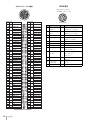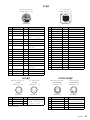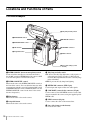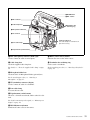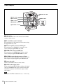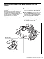
1
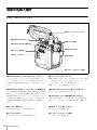
* 3
CCD BLOCK ADAPTOR
HKC-T1500
HKC-T3300
電気製品は、安全のための注意事項を守らないと、
火災や人身事故になることがあります。
このオペレーションマニュアルには、事故を防ぐための重要な注意事項と
製品の取り扱いかたを示してあります。このオペレーションマニュアルを
よくお読みのうえ、製品を安全にお使いください。お読みになったあとは、
いつでも見られるところに必ず保管してください。
OPERATION MANUAL [Japanese/English]
1st Edition (Revised 1)
-
9 9 2
-
5 1 2
-
0 2 *
(1)
日本語
安全のために
ソニー製品は安全に充分配慮して設計されています。しかし、電気製品はまちがっ
た使い方をすると、火災や感電などにより死亡や大けがなど人身事故につながるこ
とがあり、危険です。
事故を防ぐために次のことを必ずお守りください。
安全のための注意事項を守る
警告表示の意味
オペレーションマニュアルおよび
製品では、次のような表示をして
います。表示の内容をよく理解し
てから本文をお読みください。
4 ∼ 5 ページの注意事項をよくお読みください。
定期点検を実施する
この表示の注意事項を守らないと、
長期間安全に使用していただくために、定期点検を実施することをおすすめしま
す。点検の内容や費用については、ソニーのサービス担当者または営業担当者にご
火災や感電などにより死亡や大け
がなど人身事故につながることが
相談ください。
あります。
故障したら使用を中止する
ソニーのサービス担当者、または営業担当者にご連絡ください。
この表示の注意事項を守らないと、
感電やその他の事故によりけがを
万一、異常が起きたら
したり周辺の物品に損害を与えた
りすることがあります。
• 異常な音、におい、煙が出たら
• 落下させたら
注意を促す記号
m
a カメラや CCU の電源を切る。
b 接続ケーブルを抜く。
c ソニーのサービス担当者または営業担当者に修理を依頼する。
炎が出たら
行為を禁止する記号
m
すぐに接続ケーブルを抜き、消火する。
2
安全のために
行為を指示する記号
目次
警告 .................................................................................................................................. 4
注意 .................................................................................................................................. 4
その他の安全上のご注意 ........................................................................................................ 5
概要 ......................................................................................................................................... 6
商品構成 ...................................................................................................................... 6
システム構成 ............................................................................................................... 7
組み立て.................................................................................................................................. 8
手順 1:CCD ブロックアダプターからケーブルアダプターを取りはずす ................. 8
手順 2:カメラ本体の CCD ブロックを取りはずす .................................................... 8
手順 3:CCD ブロックを CCD ブロックアダプターに取り付ける ............................. 9
手順 4:ケーブルアダプターをカメラ本体に取り付ける............................................ 9
各部の名称と働き ................................................................................................................. 10
CCD ブロックアダプター.......................................................................................... 10
ケーブルアダプター .................................................................................................. 12
ケーブルアダプターとカメラ本体の接続 ............................................................................. 13
JP
アクセサリーの取り付け ...................................................................................................... 14
レンズを取り付ける .................................................................................................. 14
ビューファインダーを取り付ける............................................................................. 14
マイクを取り付ける .................................................................................................. 15
三脚に取り付ける ...................................................................................................... 16
取っ手を取りはずして使用する ................................................................................ 17
ケーブルアダプターと CCD ブロックアダプターの接続 .................................................... 18
主な仕様................................................................................................................................ 19
ピン配列 .................................................................................................................... 21
3
油煙、湯気、湿気、ほこりの
多い場所では設置・使用しな
い
上記のような場所で設置・使用すると、
火災や感電の原因となります。
機器や部品の取り付けは正し
く行う
別売りの機器や部品の取り付け方法を誤
ると、機器が落下して怪我をすることが
あります。下記の機器や部品を取り付け
るときは、マニュアルをよく読んだうえ、
分解しない、改造しない
確実に取り付けてください。
• レンズ
分解したり、改造したりすると、感電の
原因となります。
• ビューファインダー
• 三脚アダプター
内部に水や異物を入れない
ケーブルアダプターをカメラ
本体に取り付けるときは電源
を遮断する
水や異物が入ると火災や感電の原因とな
ることがあります。
万一、水や異物が入ったときは、すぐに
電源を切り、電源コードや接続コードを
抜いて、ソニーのサービス担当者または
営業担当者にご相談ください。
ビューファインダーの接眼レ
ンズを太陽に向けて放置しな
い
太陽光が接眼レンズを通してビューファ
インダー内部に焦点を結び、火災の原因
となることがあります。
ケーブルアダプターをカメラに取り付け
るときは、カメラの POWER スイッチを
OFF にするだけでなく、光電気複合ケー
ブルまたは DC IN 端子等に接続された
ケーブルを取り外してください。電源が
接続されたままでケーブルアダプターの
取り付けや取り外しを行うと、火災や故
障の原因となることがあります。
本機の構成部品の固定ネジを
しっかり締める
部品の取り付けの際は、固定ネジをしっ
かり締めてください。固定ねじを締めず
に使用すると機器が落下し、けがをする
ことがあります。
使用中、放熱口をふさがない
内部温度が上昇して、筐体でやけどする
おそれがあります。
4
警告 /
注意
ケーブルアダプターやCCDブ
ロックの交換時には、高温部
分に触れない
機器の使用直後にケーブルアダプターや
CCD ブロックを取り外し、取り付けする
その他の安全上のご注意
重要
機器の名称と電気定格は、底面に表示されています。
際には、CCD ブロックアダプターやカメ
ラ本体の内部も高温になっているため、
やけどすることがあります。交換時には、
電源を切ってから少なくとも 10 分間放置
してください。
CCDブロックアダプターやカ
メラ内部に触れない
ケーブルアダプターや CCD ブロックを
取り外し、取り付けする際には、CCD ブ
ロックアダプターやカメラ内部の部品で
指を傷つけたりすることがあります。
8 ∼ 9 ページの組み立て手順に従って処
理してください。
カメラの重量にあった三脚を
使用する
カメラ重量に耐えきれない三脚または三
脚以外に取り付けて使用すると、本機や
レンズが落下し、けがをすることがあり
ます。
三脚・雲台を確実に固定する
三脚・雲台を確実に固定せずにカメラか
ら離れると、不意にカメラが動いてけが
をすることがあります。
安定した場所に設置する
ぐらついた台の上や傾いたところなどに
三脚・雲台を設置すると、カメラが落下
してけがをすることがあります。
その他の安全上のご注意
5
VF 中継ケーブル (1 本 )
概要
ケーブルアダプターの VF 端子とカメラ本体の VF 端子を接
続することによって、CCD ブロックアダプターに取り付け
たビューファインダー / カメラ本体間の信号を中継します。
CCD ブロックアダプター HKC-T1500/T3300 は、ソニーの
HD カラーカメラ HDC1500 シリーズ /HDC3300 の CCD ブ
MIC 中継ケーブル(XLR 3 ピン)(1 本 )
ロックをカメラ本体から独立させることにより、カメラの機
動性をさらに高める CCD ブロック延長用アダプターキット
ケーブルアダプターの MIC 端子とカメラ本体の AUDIO IN
端子を接続することによって、CCD ブロックアダプターか
です。
らのマイク入力信号をカメラ本体に中継します。
対応機種
INTERCOM 中継ケーブル(XLR 5 ピン)(1 本 )
HKC-T1500
HD カラーカメラ HDC1500 シリーズ
HKC-T3300
HD カラーカメラ HDC3300
タリー / インターカムなどの信号も、独立させたブロックで
確認できるため、カメラマンはカメラ本体との距離を意識せ
ずに撮影が行えます。
カメラマンによる運搬が困難な撮影やスペースが限られてい
る場合には、アダプターの取っ手を取りはずしたり、三脚な
どに固定して使用することもできます。
商品構成
ケーブルアダプターの INTERCOM 端子とカメラ本体の
INTERCOM 1 端子を接続することによって、CCD ブロック
アダプター / カメラ本体間のインターカムの音声信号を中継
します。
上蓋 (1 個 )
CCD ブロックアダプターから取っ手を取りはずして運用す
る場合は、取っ手を取りはずした後に上蓋を取り付けます。
カメラハンガー ( 1組 )(HKC-T1500 のみ)
カメラの CCD ブロックに取り付けることによって、CCD ブ
ロックの取り付け・取りはずしを容易にします。
ケーブルクランプ (1 個 )
CCD ブロックアダプター (1 台 )
CCD ブロックアダプターに取り付けることによって、
カメラから取りはずした CCD ブロックを収納します。
カメラマンは、このアダプターと CCD ブロックのみを持ち
HDCM ケーブルをアダプター側面に固定し、操作性を上げ
ることができます。
運んで撮影を行うことができます。
ケーブルアダプター (1 台 )
取りはずした CCD ブロックの代りにカメラに取り付けま
す。
カメラ本体と CCD ブロックとの信号の受け渡しを行いま
す。
ご注意
工場出荷時は、CCD ブロックアダプターにケーブルアダプ
ターを取り付けた状態で梱包されますので、始めにケーブル
アダプターを CCD ブロックアダプターから取りはずしてく
ださい。
◆ 取りはずしかたについては、
「組み立て」(8 ページ)をご覧くだ
さい。
専用 HDCM-12 ケーブル(12.5 m)(1 本 )
CCD ブロックアダプターに取り付けた CCD ブロックとカメ
ラ本体に取り付けたケーブルアダプターを接続し、信号の受
け渡しおよび電源の供給を行います。
HKC-T1500 では、別売りの 25 m、50 m のケーブル ( 複合
ケーブル Assy ) も使用できます。
• HDCM-25(25 m):部品番号 1-820-810-11
• HDCM-50(50 m):部品番号 1-820-811-11
6
概要
システム構成
エレクトレットコンデンサーマイク
ECM-670 など
HD エレクトロニック
ビューファインダー
HDVF-20A/C35W
マイクホルダー CAC-12
HD カラーカメラ
CCD ブロックアダプター
INTERCOM
MIC
LEVEL
ON
ズームレンズ
ケーブルアダプター
OFF
FILTER
LOCAL
ND
CC
FILTER
1 CLEAR
2 1/4 ND
ND 3 1/8 ND
4 1/16ND
5 1/64ND
A CROSS
B 3200K
CC C 4300K
D 6300K
E 8000K
カメラの CCD ブロック
HKC-T1500
HDC1500 シリーズ
HKC-T3300 HDC3300
概要
7
手順 2:カメラ本体の CCD ブロック
を取りはずす
組み立て
カメラ本体から取りはずした CCD ブロックを本機の CCD
ブロックアダプターに組み込み、CCD ブロックの代りに本
機のケーブルアダプターをカメラ本体に取り付けます。
• CCD ブロックを取りはずすときは、カメラの POWER ス
イッチを OFF にしてください。
プラスドライバーをご用意ください。
• CCDブロックアダプターやカメラ内部に触れないでくださ
い。
1
手順 1:CCD ブロックアダプターか
らケーブルアダプターを取りはずす
ラ本体の CCD ブロックに取り付ける。
(HDC3300 はハンガーが取り付けられた状態で出荷され
ケーブルアダプターを固定している4 本のネジを緩める。
ていますので、この作業は必要ありません。)
T
E
R
1
M
O
C
IN
1
HDC1500 シリーズでは、カメラからレンズマウント
キャップを外し、レンズ固定レバーを図のように下まで
押し下げてから、HKC-T1500 に付属のハンガーをカメ
L
RCOM
LEVE
INTE
MIC ON
OFF
CC
R
FILTE L
LOCA
VF
CABL
12.5
MIC
ネジ
INTER
ND
E
25 50m
R
FILTE EAR
1 CL ND
2 1/4 ND
1/8
ND 3 1/16ND
4 4ND
5 1/6
OSS
A CR00K
B 3200K
43
CC C 6300K
D 00K
E 80
COM
OPT
HEAD
( 図は HKC-T1500)
片手で CCD ブロックアダプターの取っ手を押さえ、もう
片方の手でケーブルアダプターのハンガー部分をつかん
で平行に引き抜く。
HKC-T1500 に付属の
ハンガー
3
CCD ブロックを固定している 4 本のネジを緩める。
1
T
E
R
OFF
CC
R
FILTE L
LOCA
VF
CABL
12.5
MIC
INTER
OPT
ND
R
FILTE EAR
1 CL ND
2 1/4 ND
1/8 D
ND 3 1/16ND
4 4N
5 1/6
OSS
A CR00K
B 3200K
43
CC C 6300K
D 00K
E 80
E
25 50m
COM
ネジ
HEAD
CCD ブロックアダプター
ケーブルアダプター
( 図は HKC-T1500)
8
組み立て
CCD ブロック
レンズマウントキャップを元どおり取り付ける。
L
RCOM
LEVE
INTE
MIC ON
ハンガー部
HDC1500
シリーズ
2
M
O
C
IN
2
4
片手でカメラ本体の取っ手を押さえ、取り付けたハン
ガー部分をもう片方の手でつかんで平行に引き抜く。
手順 4:ケーブルアダプターをカメラ
本体に取り付ける
1
ケーブルアダプターを平行に保ち、背面のコネクターが
カメラ側のコネクターにきちんとはまるように差し込
む。
VF
CABL
12.5
MIC
INTER
E
25 50m
COM
OPT
手順 3:CCD ブロックを CCD ブ
ロックアダプターに取り付ける
1
ケーブルアダプター
( 図は HKC-T1500)
CCD ブロックを平行に保ち、CCD ブロック背面のコネ
2
ケーブルアダプターの 4 本のネジ(CCD ブロックアダプ
ターからはずすときに緩めたネジ)を締める。
T
E
R
1
M
O
C
IN
クターが CCD ブロックアダプター奥のコネクターにき
ちんとはまるように差し込む。
HEAD
L
RCOM
LEVE
INTE
MIC ON
OFF
CC
R
FILTE L
LOCA
ND
R
FILTE EAR
1 CL ND
2 1/4 ND
1/8
ND 3 1/16ND
4 4ND
5 1/6
OSS
A CR00K
B 3200K
43
CC C 6300K
D 00K
E 80
CCD ブロック
2
CCD ブロックの 4 本のネジ(カメラ本体からはずすとき
に緩めたネジ)を締める。
組み立て
9
各部の名称と働き
CCD ブロックアダプター
RET
1
INCO
M
e タリーランプとタリースイッチ
ON
OFF
IN
MIC TERCO
M
ON
LEVE
L
OFF
a INTERCOM MIC スイッチ
INTE
RCO
M
f INTERCOM 端子
b INTERCOM LEVEL 調整つまみ
Y
BOD
CAM
FILT
ER
LOCA
L
d アサイナブルボタン
ND
CC
c フィルター選択ボタン
g CAM BODY 端子
FILT
ER
1 CLE
AR
ND 2 1/4 N
3 1/8 D
4 1/16ND
5 1/64ND
ND
A CR
O
CC B 3200SS
C 43 K
D 6300K
E 8000K
00K
S
LEN
h LENS 端子
i レンズケーブルクランプ(底面)
a INTERCOM MIC(インターカムマイク)スイッチ
インターカム用ヘッドセットのマイクを ON/OFF します。
インターカム用ヘッドセットのマイクを使用するときは、カ
メラ本体の INTERCOM 用 MIC スイッチは OFF にしてく
び出し時にタリーランプが点灯します(ビューファイン
ダー内のタリ−ランプと同様に動作します)
。
ださい。
OFF:タリーランプを点灯禁止にします。
b INTERCOM LEVEL(インターカムレベル)調整つまみ
f INTERCOM(インターカム)端子(XLR 型 5 ピン)
カメラ本体前面の INTERCOM LEVEL 調整つまみと同様に
動作します。カメラ本体の INTERCOM 用 MIC スイッチを
インターカムの音声信号を入出力します。
FRONT に設定することにより、インターカム用ヘッドセッ
トの受信レベルを調整することができます(この場合、カメ
g CAM BODY(カメラ本体接続)端子(55 ピン)
ラ本体前面の INTERCOM LEVEL 調整つまみは無効になり
ます)。
10
e タリーランプとタリースイッチ
ON: 外部からのタリーボタンや CALL ボタンなどによる呼
付属の専用 HDCM ケーブルを使用して、カメラ本体に取り
付けたケーブルアダプターの OPT HEAD 端子と接続しま
す。
c フィルター選択ボタン
カメラの対応するボタンと同様に機能します。
h LENS(レンズ)端子(12 ピン)
d アサイナブルボタン
カメラの対応するボタンと同様に機能します。
i レンズケーブルクランプ(底面)
各部の名称と働き
レンズのケーブルを接続します。
レンズのケーブルを固定します。
p INCOM ボタン
q RET 1 ボタン
1
RET
OM
INC
j MIC 端子
MIC
k ケーブルクランプ取り付け部
VF
r ビューファインダーシュー
と固定リング
l マイクホルダー取り付け部
m VF 端子
n レンズケーブルクランプ
カメラの CCD ブロック
(工場出荷時はケーブルアダプターが取り
付けられています。
)
o 三脚マウント用ネジ穴(底面)
j MIC(マイク)端子(XLR 型 3 ピン)
マイクのケーブルを接続します。
q RET 1(リターンビデオ 1)ボタン
カメラの対応するボタンと同様に機能します。
k ケーブルクランプ取り付け部
付属のケーブルクランプを取り付けます。
r ビューファインダーシューと固定リング
ビューファインダーを取り付けます。
◆ 詳しくは「ケーブルクランプ(付属)の使いかた」(18 ページ)
をご覧ください。
◆ 取り付けかたについては「ビューファインダーを取り付ける」
(14 ページ)をご覧ください。
l マイクホルダー取り付け部
マイクホルダー CAC-12(別売り)を取り付けます。
◆ 詳しくは「マイクを取り付ける」
(15 ページ)をご覧ください。
m VF(ビューファインダー)端子(20 ピン)
ビューファインダーのケーブルを接続します。
n レンズケーブルクランプ
レンズのケーブルを固定します。
o 三脚マウント用ネジ穴(底面)
3
4 インチおよび /8 インチのネジ穴があります。
1/
◆ 取り付けかたについては「三脚に取り付ける」
(16 ページ)をご
覧ください。
p INCOM(インターカム)ボタン
カメラの対応するボタンと同様に機能します。
各部の名称と働き
11
ケーブルアダプター
f カメラレンズケーブル
a ケーブルクランプ
VF
b VF 端子
MIC
CABLE
12.5 25 50m
INTERCO
M
c MIC 端子
CABLE
12.5m
d INTERCOM 端子
OPT HEAD
e OPT HEAD 端子
a ケーブルクランプ
カメラ本体の LENS 端子に接続したカメラレンズケーブル
を固定します。
b VF(ビューファインダー)端子(20 ピン)
付属の VF 中継ケーブルを使用して、カメラ本体の VF 端子
と接続します。
c MIC(マイク)端子(XLR 型 3 ピン)
付属の MIC 中継ケーブルを使用して、カメラ本体の
AUDIO IN 1 端子と接続します。
d INTERCOM(インターカム)端子(XLR 型 5 ピン)
付属の INTERCOM 中継ケーブルを使用して、カメラ本体
の INTERCOM 1 端子と接続します。
e OPT HEAD(光学ヘッド)端子(55 ピン)
付属の専用 HDCM ケーブルを使用して、CCD ブロックアダ
プターの CAM BODY 端子と接続します。
f カメラレンズケーブル
カメラ本体の LENS 端子に接続します。
g CABLE(ケーブル長切り換え)スイッチ
HKC-T1500 では、CCD ブロックアダプターに取り付けた
CCD ブロックとカメラ本体に取り付けたケーブルアダプ
ターを接続する専用 HDCM ケーブルの長さに合わせて設定
します。
ご注意
HKC-T3300 では、12.5 m 以外には設定できません。
12
各部の名称と働き
g CABLE スイッチ
INTERCOM
HKC-T3300
ケーブルアダプターとカメラ本体の接続
カメラ本体に取り付けたケーブルアダプターとカメラ本体を
次のように接続します。
ただし、インターカム、マイク、ビューファインダーを
CCD ブロック側で使用しない場合は、これらの接続は必要
ありません。通常通りカメラ本体の VF コネクターにビュー
ファインダーを接続してください。
1
ケーブルアダプターのカメラレンズケーブルのコネク
ターをカメラ本体の LENS 端子に接続し、ケーブルを
ケーブルクランプにはめ込む。
2
VF 中継ケーブル(HKC-T1500/T3300 に付属)で、カメ
ラ本体の VF 端子とケーブルアダプターの VF 端子を接
続する。
3
INTERCOM 中継ケーブル(HKC-T1500/T3300 に付属)
で、カメラ本体後面の INTERCOM 1 端子とケーブルア
ダプターの INTERCOM 端子を接続する。
4
MIC 中継ケーブル(HKC-T1500/T3300 に付属)で、カ
メラ本体後面の AUDIO IN 1 端子とケーブルアダプター
の MIC 端子を接続し、AUDIO IN 1 端子用の入力選択
スイッチを MIC に設定する。
3
2
VF
MIC
4
1
CA25BLE
50m
12.5
INTERC
3
OM
OPT HE
AD
4
カメラ本体後面
INTE
RCO
M1
INTE
RCO
M2
( 図は HKC-T1500)
3
RET
CTRL
EARPH
ONE
TRAC
KER
LINE
DC
DC INOUT
10.517
FR
MIC ONT MIC
+48V
OFF
REM
OTE
CRAN
E
LINE
V
AUDIO
IN
RET
IN
GENL
OC
K IN
PROM
PTER
AE
MIC S/EBU
+48V
OFF
CH1
CH2
4
TEST
OUT
SDI2
AUDIO IN 1 端子
INTERCOM 1 端子
入力選択スイッチ:MIC に
ケーブルアダプターとカメラ本体の接続
13
4
アクセサリーの取り付け
レンズケーブルを LENS 端子に接続し、レンズケーブル
を底面のケーブルクランプに押し込む。
INCO
レンズを取り付ける
RET
1
M
OFF
ON
CCD ブロックアダプターにマウントした CCD ブロックに、
VF
INTE
レンズを取り付けます。
M
MIC
CAM
BOD
Y
◆ レンズの取り扱いについては、レンズに付属の取扱説明書をご覧
ください。
1
RCO
レンズ固定レバーを押し上げて、レンズマウントからレ
LENS
ンズマウントキャップをはずす。
T
E
R
1
M
O
C
IN
底面
LENS 端子へ
ケーブルクランプ
OM L
TERC LEVE
IN
MIC ON
OFF
CC
R
FILTE L
LOCA
ND
R
FILTE EAR
1 CL ND
2 1/4 ND
1/8 D
ND 3 1/16ND
4 4N
5 1/6
OSS
A CR00K
B 3200K
43
CC C 6300K
D 00K
E 80
ビューファインダーを取り付ける
レンズ固定レバー
ビューファインダーを取り付けたあと、接眼レンズを太陽に
2
レンズマウント上部中央の凹部にレンズの位置決めピン
を合わせ、レンズをマウントに差し込む。
向けて放置しないでください。太陽光が接眼レンズを通して
ビューファインダー内部に焦点を結び、火災の原因となるこ
とがあります。
T
E
R
1
M
O
C
IN
CCD ブロックアダプターにビューファインダー HDVF20A/C35W(別売り)を取り付けます。(図は HDVF-20A で
す。
)
L
RCOM
LEVE
INTE
MIC ON
OFF
CC
R
FILTE L
LOCA
ND
1
ビューファインダーを矢印の方向にスライドさせて取り
付ける。
R
FILTE EAR
1 CL ND
2 1/4 ND
1/8 D
ND 3 1/16ND
4 4N
5 1/6
OSS
A CR00K
B 3200K
43
CC C 6300K
D 00K
E 80
凹部
3
14
レンズを支えながら、レンズ固定レバーを押し下げてレ
ンズを固定する。
アクセサリーの取り付け
ストッパーは自動的に下がります。
例:HDVF-20A
マイクを取り付ける
HDVF-20A のマイクホルダーを使用する
IN
C
O
M
R
E
T
1
ビューファインダー HDVF-20A を取り付けたときは、
HDVF-20A のマイクホルダーにマイクを取り付けることが
MIC
VF
できます。
1
ネジを緩めてマイクホルダーを開け、マイクを載せる。
ストッパー
IN
C
O
M
R
E
T
1
MIC
VF
2
ビューファインダー固定リングを回して締め、ビュー
ファインダーケーブルを CCD ブロックアダプターの
2
1
VF 端子に接続する。
IN
C
O
M
R
E
T
1
1
MIC
VF
2
2
マイクホルダーを元通りに閉めてネジを締め、マイク
ケーブルを CCD ブロックアダプターの MIC 端子に接続
する。
IN
C
O
M
R
E
T
1
MIC
3
取りはずすときは
1
VF
1
2
ビューファインダーケーブルを VF 端子からはずし、
ビューファインダー固定リングを取り付け時と逆の方向
に回して緩める。
2
ビューファインダーストッパーを上げて、ビューファイ
ンダーを取り付け時と逆の方向にスライドさせて抜き取
る。
マイクホルダー CAC-12(別売り)を使用
する
ビューファインダーを使用しないとき、または HDVFC35W を取り付けたときは、マイクホルダー CAC-12(別売
り)を使って、マイクを CCD ブロックアダプターに取り付
けることができます。
1
付属の M3 × 8 ネジ 2 本を使って、CCD ブロックアダプ
ターのマイクホルダー取り付け部にマイクホルダー
CAC-12 を取り付ける。
アクセサリーの取り付け
15
4
M3 × 8 ネジ(付属)
マイクの接続ケーブルをCCDブロックアダプターのMIC
端子に接続する。
INCOM
RET
1
三脚に取り付ける
OFF
ON
VF
INTE
CCD ブロックアダプターの底面には、1/4 インチおよび 3/8
RCOM
MIC
CAM
BODY
CAC-12
CAC-12 からマイクロホンアダプターを取り出す。
T
E
R
1
M
O
C
IN
2
インチのネジ穴があります。使用する三脚のネジに応じた穴
を使用して取り付けてください。
L
RCOM
LEVE
INTE
MIC ON
OFF
RET
INCOM
1
CAC-12 を開く。
2
CC
R
FILTE L
LOCA
ND
OFF
ON
R
FILTE EAR
1 CL ND
2 1/4 ND
1/8
ND 3 1/16ND
4 4ND
5 1/6
OSS
A CR00K
B 3200K
43
CC C 6300K
D 00K
E 80
3
VF
INTE
RCOM
MIC
1
CAM
BODY
ネジをゆるめる。
マイクロホンアダプター
LENS
雲台
ご注意
径が細いマイクを取り付ける場合は、マイクロホンアダ
プターを装着したまま使用してください。
3
CCD ブロック
アダプター底面
マイクを CAC-12 に取り付ける。
1/
4
CAC-12 を閉める。
INCOM
RET
1
2
1
OFF
ON
VF
INTE
RCOM
MIC
CAM
BODY
マイク
LENS
INCOM
RET
1
3
OFF
ON
VF
INTE
RCOM
MIC
CAM
BODY
16
アクセサリーの取り付け
ネジを締める。
インチ三脚ネジ
3/
8
インチ三脚ネジ
取っ手を取りはずして使用する
3
付属の上蓋を取り付け、4 本のネジを締める。
限られたスペースに設置する場合などは、CCD ブロックか
ら取っ手を取りはずして運用することができます。
取りはずした後は、付属の上蓋を取り付けてください。
1
CAM
BOD
Y
取っ手を固定している 4 本のネジを緩める。
INCO
RET
1
LENS
M
OFF
ON
VF
INTE
RCO
M
MIC
取っ手を再度取り付けるときは
CAM
BOD
Y
取りはずしと逆の手順で取り付けます。
ご注意
LENS
取っ手のネジを締める前に、取っ手と本体の間にハーネスが
挟まれていないか確認してください。挟まれた状態でネジを
締めると断線する恐れがあります。
2
取っ手を持ち上げて、ハーネスをはずす。
INCO
RET
1
M
OFF
ON
VF
INTE
RCO
M
MIC
ハーネス
CAM
BOD
Y
LENS
アクセサリーの取り付け
17
ケーブルアダプターと CCD ブロックアダプターの接続
付属の専用 HDCM ケーブル(12.5 m)を使用して、ケーブ
ルアダプターの OPT HEAD 端子と CCD ブロックアダプ
ターの CAM BODY 端子を接続します。
HKC-T1500 では、別売りの HDCM ケーブル(25 m または
50 m)も使用できます。
ご注意
• カメラ本体と CCD ブロックは、必ずシリアル番号が同じも
のを組み合わせてご使用ください。
• HKC-T1500/T3300 を使用するときは、カメラ本体のソフ
トウェアを最新のバージョンにしてください。
HDC1500 シリーズではバージョンが 1.10 より古い場合、
また HDC3300 ではバージョンが 1.06 より古い場合動作し
ません。
CABLE スイッチ(図は HKC-T1500):
HKC-T1500 では、使用する HDCM ケーブルの長さに合わせて設定
(HKC-T3300 は 12.5 m に固定)
IN
OFF
ON
VF
VF
MIC
INTE
CA25BLE
50m
12.5
INTERC
RCO
M
MIC
OM
CAM
BOD
Y
OPT HE
AD
付属の専用 HDCM ケーブル
(HKC-T1500 では別売り
ケーブルも使用可 )
ケーブルアダプターの
OPT HEAD 端子へ
ケーブルクランプ(付属)の使いかた
付属のケーブルクランプを使用して、HDCM ケーブルを
CCD ブロックアダプターに固定することができます。
LENS
CCD ブロックアダプターの
CAM BODY 端子へ
2
HDCM ケーブルをケーブルクランプに挟み、ケーブルク
ランプを閉める。
OFF
ON
1
付属のケーブルクランプを組み立て、付属のネジ(M3
× 10)を使って CCD ブロックアダプターのケーブルク
ランプ取り付け部に取り付ける。
VF
INTE
RCOM
MIC
CAM
BODY
HDCM ケーブル
LENS
OFF
ON
M3 × 10 ネジ
VF
INTE
RCOM
MIC
INCOM
RET
1
ケーブルクランプ
CAM
BODY
OFF
ON
VF
INTE
LENS
RCOM
MIC
CAM
BODY
18
ケーブルアダプターと CCD ブロックアダプターの接続
主な仕様
電源電圧
動作温度
13.5 ∼ 17.0 V DC
− 20 ℃∼+ 45 ℃
ケーブルクランプ(1)
ネジ : M3 × 10(2)
動作湿度
質量
10%∼ 90%(結露なし)
ケーブルアダプター:約 0.5 kg
M3 × 8(2)
オペレーションマニュアル(1)
CCD ブロックアダプター
・本体のみ:約 1.05 kg
別売品 (HKC-T1500 のみ使用可)
複合ケーブル Assy
・CCD ブロック組み込み時:約 1.8 kg
HDCM-12 ケーブル(12.5 m)(1)
付属品
HDCM-25(25 m)
:部品番号 1-820-810-11
HDCM-50(50 m)
:部品番号 1-820-811-11
VF 中継ケーブル(1)
MIC 中継ケーブル(1)
INTERCOM 中継ケーブル(1)
本機の仕様および外観は、改良のため予告なく変更すること
がありますが、ご了承ください。
上蓋(1)
カメラハンガー(1組)(HKC-T1500 の
み)
寸法図(1)取っ手使用時
(単位:mm)
226
OFF
ON
INTERCOM
INTERCOM
MIC
LEVEL
ON
OFF
ND
233.3
CAM BODY
FILTER
LOCAL
CC
140.2
FILTER
1 CLEAR
2 1/4 ND
ND 3 1/8 ND
4 1/16ND
5 1/64ND
LENS
8
58.3
A CROSS
B 3200K
CC C 4300K
D 6300K
E 8000K
65
4
63
11.5
128
120
142.5
カメラの CCD ブロック取り付け時
27.5
4
インチ三脚ネジ、深 7.5
16.5
3/
8
インチ三脚ネジ、深 10
38
1/
4-M4、深 8
25.5
60.5
レンズ取り付け面
主な仕様
19
寸法図(2)上蓋取り付け時
(単位:mm)
42
46
35
CAM BODY
4-M3
質量:約 1.58 kg
CAM BODY
ND
CC
140.2
FILTER
1 CLEAR
2 1/4 ND
ND 3 1/8 ND
4 1/16ND
5 1/64ND
LENS
8
58.3
A CROSS
B 3200K
CC C 4300K
D 6300K
E 8000K
158.3
FILTER
LOCAL
65
63
128
カメラの CCD ブロック取り付け時
/4 インチ三脚ネジ、深 7.5
3
/8 インチ三脚ネジ、深 10
38
1
レンズ取り付け面
お使いになる前に、必ず動作確認を行ってください。故障
その他に伴う営業上の機会損失等は保証期間中および保証
期間経過後にかかわらず、補償はいたしかねますのでご了
承ください。
20
主な仕様
4-M4、深 8
ピン配列
マルチコネクター
CCD ブロックアダプター
CAM BODY 端子(55 ピン、凸)
1
ケーブルアダプター
OPT HEAD 端子(55 ピン、凹)
3
3
X
1
Z
Z
X
Y
Y
TMW
53
TMW
55
55
(External View)
信号
I/O1) 仕様
1
R1 VIDEO (X)
OUT
2
R1 VIDEO (G)
−
3
R2 VIDEO (X)
OUT
4
G1 VIDEO (G)
−
5
G1 VIDEO (X)
6
7
8
9
No.
53
(External View)
No.
信号
I/O1) 仕様
Zo = 75 ohms
29
UNREG GND
−
GND for UNREG
GND for R VIDEO
30
UNREG GND
−
GND for UNREG
Zo = 75 ohms
31
INCOM MIC (Y)
GND for G VIDEO
32
NC
OUT
Zo = 75 ohms
33
PLL-H (X) -GND
G2 VIDEO (X)
OUT
Zo = 75 ohms
34
PLL-H (Y) -GND
−
G2 VIDEO (G)
−
GND for G VIDEO
35
F-acum
IN
R2 VIDEO (G)
−
GND for R VIDEO
36
LENS UNREG
IN
IRIS CONT
IN
+3.4 V (F16) to +6.2 V (F2.8)
37
INCOM Receive
IN
0 dBu
10
B1 VIDEO (G)
−
GND for B VIDEO
38
VF Pb VIDEO (X)
IN
Zi = 75 ohms
11
B1 VIDEO (X)
OUT
Zo = 75 ohms
39
VF Pb VIDEO (G)
−
GND for VF VIDEO
12
B2 VIDEO (X)
OUT
Zo = 75 ohms
40
RX COMMAND (X)
13
B2 VIDEO (G)
−
GND for B VIDEO
41
PLL-H (X)
14
OHB H (G)
−
GND for OHB H
42
15
MIC GND
−
GND
43
16
INCOM GND
−
GND
44
PGM
IN
17
GND (CHU-F)
−
45
VF Pr VIDEO (X)
IN
500 mVp-p, Zi = 75 ohms
18
NC
46
VF Pr VIDEO (G)
−
GND for VF VIDEO
No connection
OUT
No connection
−
OUT
Zo = 100 ohms
IN
Positive pulse
PLL-H (Y)
IN
Negative pulse
HTSG
IN
0 dBu
19
NC
No connection
47
RX COMMAND (Y)
OUT
Zo = 100 ohms
20
NC
No connection
48
TX COMMAND (X)
IN
Zo = 100 ohms
21
OHB H (for PLL)
Positive pulse
49
LENS RX (X)
IN
Zo = 100 ohms
22
MIC (X)
OUT
− 60 dBu, − 50 dBu, − 40 dBu,
50
LENS TX (X)
OUT
23
MIC (Y)
OUT
− 30 dBu, − 20 dBu, selectable
51
VF Y VIDEO (X)
IN
Zi = 75 ohms
24
INCOM MIC (X)
OUT
− 20 dBu (CARBON MIC),
52
VF Y VIDEO (G)
−
GND for VF VIDEO
OUT
Zo = 100 ohms
− 60 dBu (DYNAMIC MIC)
25
CHU F
IN
53
TX COMMAND (Y)
IN
Zo = 100 ohms
26
UNREG
IN
Positive pulse
54
LENS RX (Y)
IN
Zo = 100 ohms
27
UNREG
IN
55
LENS TX (Y)
OUT
Zo = 100 ohms
28
GND (LENS UNREG)
IN
1) 表に示す IN/OUT は CCD ブロックアダプター CAM BODY 端子側から見た場合です。
ケーブルアダプター OPT HEAD 端子側から見た場合、IN/OUT が逆になります。
主な仕様
21
36 心カメラケーブルの接続
1
7
18
19
6
16
17
Signal
26, 27 33, 34 UNREG
29, 30 35, 36 UNREG GND
21
21 OHB H (for PLL)
OHB H (G)
14
5
7 G1 VIDEO (X)
G1 VIDEO (G)
4
6
1 G2 VIDEO (X)
G2 VIDEO (G)
7
1
2 R1 VIDEO (X)
R1 VIDEO (G)
2
3
3 R2 VIDEO (X)
R2 VIDEO (G)
8
11
5 B1 VIDEO (X)
10
B1 VIDEO (G)
12
6 B2 VIDEO (X)
13
B2 VIDEO (G)
22
8 MIC (X)
23
9 MIC (Y)
15
MIC GND
9
32 IRIS CONT
41
20 PLL-H (X)
33
PLL-H (X) -GND
37
28 INCOM Receive
24
10 INCOM MIC (X)
31
11 INCOM MIC (Y)
16
INCOM GND
44
29 PGM
51
4 VF Y VIDEO (X)
52
VF Y VIDEO (G)
38
22 VF Pb VIDEO (X)
39
VF Pb VIDEO (G)
45
23 VF Pr VIDEO (X)
46
VF Pr VIDEO (G)
48
16 TX COMMAND (X)
53
17 TX COMMAND (Y)
Shell
18 RX COMMAND (X)
40
19 RX COMMAND (Y)
47
Shell
24 CHU F
25
17
GND (CHU-F)
25 PLL-H (Y)
42
34
PLL-H (Y) -GND
31 F-acum
35
30 HTSG
43
12 LENS TX (X)
50
13 LENS TX (Y)
55
Shell
14 LENS RX (X)
49
15 LENS RX (Y)
54
Shell
26 LENS UNREG
36
27 GND (LENS UNREG)
28
(Shell)
22
主な仕様
2
28
33
36
34
31
21
29
35
27
5
55-pin Cond.
No. No.
CCD ブロックアダプター
LENS 端子(12 ピン、凹)
8
9
25 20 26
32
24
22
23
14
15
LENS 端子
30
10
11
9 1
10 2
7 12 11 3
6
4
5
3
8
12
13
4
55-pin Cond.
No. No.
(External View)
Wire
26, 27 33, 34 UL1516 #20 x2
29, 30 35, 36 UL1516 #20 x2
21
21 UL1721 #28
14
5
7 UL1631 #30
4
6
1 UL1631 #30
7
1
2 UL1631 #30
2
3
3 UL1631 #30
8
11
5 UL1631 #30
10
12
6 UL1631 #30
13
22
8 UL2854-2 #28
23
9 UL2854-2 #28
15
9
32 UL1423 #26
41
20 UL1721 #28
33
37
28 UL1423 #26
24
10 UL2854-2 #28
31
11 UL2854-2 #28
16
44
29 UL1423 #26
51
4 UL1631 #30
52
38
22 UL1721 #28
39
45
23 UL1721 #28
46
48
16 UL2854-2 #28
53
17 UL2854-2 #28
18 UL2854-2 #28
40
19 UL2854-2 #28
47
24 UL1721 #28
25
17
25 UL1721 #28
42
34
31 UL1423 #26
35
30 UL1423 #26
43
12 UL2854-2 #28
50
13 UL2854-2 #28
55
14 UL2854-2 #28
49
15 UL2854-2 #28
54
26 UL1516 #20 x1
36
27 UL1516 #20 x1
28
(Shell)
No.
1
信号
I/O
仕様
RET VIDEO
IN
ENABLE: 0 V
ENABLE
2
VTR START/
DISABLE: +5 V or OPEN
IN
STOP
ENABLE: 0 V
DISABLE: +5 V or OPEN
3
GND
−
GND for UNREG
4
AUTO SERVO
OUT AUTO: +5 V
5
IRIS CONT
OUT +3.4 V (F16) to +6.2 V (F2.8)
6
UNREG
OUT +10.5 V to +17 V
7
IRIS POSITION
8
AUTO/MANU
9
EXTENDER
MANU: 0 V or OPEN
IN
+3.4 V (F16) to +6.2 V (F2.8)
OUT AUTO IRIS: 0 V
MANUAL IRIS: +5 V
IN
ON/OFF
EX 2 ON: 0 V
EX 0.8 ON: +1.8 V
OFF: +4.8 V
10
ZOOM POSITION
IN
WIDE: 2 V
TELE: 7 V
11
FOCUS POSI
IN
(/LENS RX)
12
(/LENS TX)
∞: 2 V
min.: 7 V
OUT
VF 端子
CCD ブロックアダプター
VF 端子(20 ピン、凹)
ケーブルアダプター
VF 端子(20 ピン、凹)
3 2 1
8 7 6 5 4
12 11 10 9
No.
信号
1
2
3
4
6
7
8
9 10
5
11 12 13 14 15
17 16 15 14 13
20 19 18
16 17 18 19 20
(External View)
(External View)
I/O
仕様
IN/OUT TTL level
No.
信号
I/O
仕様
1
S DATA
1
NC
No connection
2
NC
No connection
2
NC
No connection
3
NC
No connection
3
NC
No connection
4
SCK
OUT
TTL level
4
NC
No connection
MANU: 0 V or OPEN
5
NC
No connection
5
NC
No connection
6
NC
No connection
6
NC
No connection
7
NC
No connection
7
NC
No connection
8
NC
No connection
8
G TALLY
OUT
ON: 5 V
9
NC
No connection
OFF: GND
10
NC
No connection
NC
No connection
9
NC
No connection
11
10
NC
No connection
12
Y VIDEO
IN
1.0 Vp-p, Zi = 75 ohms
11
NC
No connection
13
VIDEO GND
−
GND for VIDEO
12
Y VIDEO
1.0 Vp-p, Zo = 75 ohms
14
Pb VIDEO
IN
700 mVp-p, Zo = 75 ohms
13
VIDEO GND
GND for VIDEO
15
Pr VIDEO
IN
14
Pb VIDEO
OUT
700 mVp-p, Zo = 75 ohms
16
NC
No connection
15
Pr VIDEO
OUT
16
NC
17
R TALLY
OUT
−
OUT
700 mVp-p, Zo = 75 ohms
17
NC
No connection
No connection
18
NC
No connection
ON: 5 V
19
NC
No connection
20
NC
No connection
OFF: GND
18
NC
19
UNREG GND
20
UNREG
No connection
−
GND for UNREG
OUT
INTERCOM 端子
MIC 端子
CCD ブロックアダプター
MIC 端子
(XLR 3 ピン、凹)
1
2
3
3
(External View)
(External View)
AUDIO (G)
AUDIO (X)
AUDIO (Y)
(0 dBu = 0.775 Vrms)
I/O
仕様
ケーブルアダプター
INTERCOM 端子
(XLR 5 ピン、凸)
1
5
2
1
3
信号
CCD ブロックアダプター
INTERCOM 端子
(XLR 5 ピン、凹)
ケーブルアダプター
MIC 端子
(XLR 3 ピン、凸)
1
2
No.
700 mVp-p, Zo = 75 ohms
4
3
2
(External View)
No.
信号
5
1
2
3
4
(External View)
I/O
仕様
−
− 60 dBu, − 50 dBu, − 40 dBu,
1
INTERCOM MIC (Y)
IN
− 20 dBu (CARBON MIC)
IN
− 30 dBu, − 20 dBu, selectable
2
INTERCOM MIC (X)
IN
− 60 dBu (DYNAMIC MIC)
IN
High impedance, balanced
3
GND(INTERCOM PGM)
4
INTERCOM RECEIVE
OUT 0 dBu
5
PGM
OUT 0 dBu
−
(0 dBu = 0.775 Vrms)
主な仕様
23
English
WARNING
To reduce the risk of fire or electric shock,
do not expose this apparatus to rain or
moisture.
IMPORTANT
The nameplate is located on the bottom.
CAUTION
Sharp objects and edges inside the camera. Beware of injury.
For the customers in the U.S.A.
This equipment has been tested and found to comply with the
limits for a Class A digital device, pursuant to Part 15 of the
FCC Rules. These limits are designed to provide reasonable
protection against harmful interference when the equipment is
operated in a commercial environment. This equipment
generates, uses, and can radiate radio frequency energy and,
if not installed and used in accordance with the instruction
manual, may cause harmful interference to radio
communications. Operation of this equipment in a residential
area is likely to cause harmful interference in which case the
user will be required to correct the interference at his own
expense.
You are cautioned that any changes or modifications not
expressly approved in this manual could void your authority to
operate this equipment.
All interface cables used to connect peripherals must be
shielded in order to comply with the limits for a digital device
pursuant to Subpart B of Part 15 of FCC Rules.
For the customers in Europe
This product with the CE marking complies with the EMC
Directive issued by the Commission of the European
Community.
Compliance with this directive implies conformity to the
following European standards:
• EN55103-1: Electromagnetic Interference (Emission)
• EN55103-2: Electromagnetic Susceptibility (Immunity)
This product is intended for use in the following
Electromagnetic Environments:
E1 (residential), E2 (commercial and light industrial),
E3 (urban outdoors) and E4 (controlled EMC environment, ex.
TV studio).
The manufacturer of this product is Sony Corporation, 1-7-1
Konan, Minato-ku, Tokyo, Japan.
The Authorized Representative for EMC and product safety is
Sony Deutschland GmbH, Hedelfinger Strasse 61, 70327
Stuttgart, Germany. For any service or guarantee matters
please refer to the addresses given in separate service or
guarantee documents.
AVERTISSEMENT
Afin de réduire les risques d’incendie ou
d’électrocution, ne pas exposer cet
appareil à la pluie ou à l’humidité.
24
IMPORTANT
La plaque signalétique se situe sous l’appareil.
Pour les clients européens
Ce produit portant la marque CE est conforme à la Directive
sur la compatibilité électromagnétique (EMC) émise par la
Commission de la Communauté européenne.
La conformité à cette directive implique la conformité aux
normes européennes suivantes:
• EN55103-1: Interférences électromagnétiques (émission)
• EN55103-2: Sensibilité électromagnétique (immunité)
Ce produit est prévu pour être utilisé dans les environnements
électromagnétiques suivants:
E1 (résidentiel), E2 (commercial et industrie légère), E3
(urbain extérieur) et E4 (environnement EMC contrôlé, ex.
studio de télévision).
Le fabricant de ce produit est Sony Corporation, 1-7-1 Konan,
Minato-ku, Tokyo, Japon.
Le représentant autorisé pour EMC et la sécurité des produits
est Sony Deutschland GmbH, Hedelfinger Strasse 61, 70327
Stuttgart, Allemagne. Pour toute question concernant le
service ou lagarantie, veuillez consulter les adresses
indiquées dans les documents de service ou de garantie
séparés.
WARNUNG
Um die Gefahr von Bränden oder
elektrischen Schlägen zu verringern, darf
dieses Gerät nicht Regen oder Feuchtigkeit
ausgesetzt werden.
WICHTIG
Das Namensschild befindet sich auf der Unterseite des
Gerätes.
Für Kunden in Europa
Dieses Produkt besitzt die CE-Kennzeichnung und erfüllt die
EMV-Richtlinie der EG-Kommission.
Angewandte Normen:
• EN55103-1: Elektromagnetische Verträglichkeit
(Störaussendung)
• EN55103-2: Elektromagnetische Verträglichkeit
(Störfestigkeit),
Für die folgenden elektromagnetischen Umgebungen:
E1 (Wohnberelch), E2 (kommerzieller und in beschränktem
Maße industrieller Bereich), E3 (Stadtbereich im Freien) und
E4 (kontrollierter EMV-Bereich, z.B. Fernsehstudio).
Der Hersteller dieses Produkts ist Sony Corporation, 1-7-1
Konan, Minato-ku, Tokyo, Japan.
Der autorisierte Repräsentant für EMV und Produktsicherheit
ist Sony Deutschland GmbH, Hedelfinger Strasse 61, 70327
Stuttgart, Deutschland. Bei jeglichen Angelegenheiten in
Bezug auf Kundendienst oder Garantie wenden Sie sich bitte
an die in den separaten Kundendienst- oder
Garantiedokumenten aufgeführten Anschriften.
Table of Contents
Overview................................................................................26
Product Configuration................................................................26
System Configuration ................................................................27
Assembly...............................................................................28
Step 1: Removing the Cable Adaptor from the CCD Block
Adaptor ...........................................................................28
Step 2: Removing the CCD Block from the Camera.................28
Step 3: Mounting the CCD Block to the CCD Block Adaptor..29
Step 4: Mounting the Cable Adaptor to the Camera..................29
Locations and Functions of Parts.......................................30
CCD Block Adaptor...................................................................30
Cable Adaptor ............................................................................32
Connecting Between the Cable Adaptor and the Camera 33
Attaching the Accessories...................................................34
Attaching a Lens ........................................................................34
Attaching a Viewfinder..............................................................34 GB
Attaching a Microphone ............................................................35
Mounting on a Tripod ................................................................36
Using the CCD Block Adaptor Without the Handle..................37
Connecting Between the Cable Adaptor and CCD Block
Adaptor...........................................................................38
Specifications .......................................................................39
Pin Assignments ........................................................................41
Table of Contents
25
Overview
The HKC-T1500 and the HKC-T3300 CCD Block
Adaptors are adaptor kits for CCD block extension. They
provide you higher mobility by separating the CCD block
of an Sony HDC1500-series/HDC3300 HD Color Camera
from the camera.
Applicable models
HKC-T1500
HDC1500-series HD color cameras
HKC-T3300
HDC3300 HD color camera
As the tally/intercom signals can be checked also on the
separated block, you can perform your shooting without
worrying about the distance from the camera.
In a shooting situation for which you cannot carry the
camera, or in limited space, you can detach the handle
from the separated block and can also fix the block to a
tripod.
Product Configuration
CCD block adaptor (1 ea.)
This adaptor accommodates the CCD block separated
from the camera.
You can perform your shooting by carrying only the CCD
block mounted in this adaptor.
Cable adaptor (1 ea.)
Being mounted in the camera in place of the CCD block of
the camera, this adaptor relays signals between the camera
and the CCD block.
Note
As the HKC-T1500/T3300 is shipped from the factory
with the cable adaptor mounted in the CCD block adaptor,
it is necessary to detach the cable adaptor from the CCD
block adaptor first.
For the detaching procedure, see “Assembly” on page 28.
HDCM-12 cable (12.5 m) (1 ea.)
This cable connects between the CCD block mounted in
the CCD block adaptor and the cable adaptor mounted in
the camera and relays signals and operating power.
For the HKC-T1500, longer cables are available as options
(Multicore Cables):
• HDCM-25 (25 m): Part number 1-820-810-11
• HDCM-50 (50 m): Part number 1-820-811-11
26
Overview
VF relay cable (1 ea.)
Connecting the VF connector of the cable adaptor and the
VF connector of the camera, this cable relays signals
between the viewfinder attached to the CCD block adaptor
and the camera.
MIC relay cable (XLR 3-pin) (1 ea.)
Connecting the MIC connector of the cable adaptor and the
AUDIO IN connector of the camera, this cable relays the
microphone input signals from the CCD block adaptor to
the camera.
INTERCOM relay cable (XLR 5-pin) (1 ea.)
Connecting the INTERCOM connector of the cable
adaptor and the INTERCOM 1 connector of the camera,
this cable relays audio intercom signals between the CCD
block adaptor and the camera.
Top cover (1 ea.)
To use the CCD block adaptor without the handle, attach
this cover in place of the handle.
Camera hanger (1 pair) (HKC-T1500 only)
Attaching these hangers to the CCD block of the camera
makes the task of mounting/unmounting the CCD block
easy.
Cable clamp (1 ea.)
Attaching this clamp to the CCD block adaptor improves
operability by fixing the HDCM cable to the side of the
adaptor.
System Configuration
ECM-670 Electret Condenser
Microphone, etc.
HDVF-20A /C35W
HD Electronic Viewfinder
CAC-12 Microphone Holder
CCD block adaptor
HD Color Camera
Cable adaptor
INTERCOM
MIC
LEVEL
ON
OFF
Zoom lens
FILTER
LOCAL
ND
CC
FILTER
1 CLEAR
2 1/4 ND
ND 3 1/8 ND
4 1/16ND
5 1/64ND
A CROSS
B 3200K
CC C 4300K
D 6300K
E 8000K
CCD block of the camera
HKC-T1500
HKC-T3300
HDC1500-series
HDC3300
Overview
27
Step 2: Removing the CCD Block
from the Camera
Assembly
Mount the CCD block detached from the camera to the
CCD block adaptor then mount the cable adaptor of the
HKC-T1500/T3300 to the camera in its place.
Use a Phillips screwdriver.
Caution
• Before removing the CCD block, set the POWER switch
of the camera to OFF.
• Do not touch any parts inside the CCD block adaptor and
the camera.
1
Step 1: Removing the Cable Adaptor
from the CCD Block Adaptor
Loosen the four screws holding the cable adaptor.
T
E
R
1
M
O
C
IN
1
For an HDC1500-series camera, first remove the lens
mount cap from the camera and turn the lens fixing
lever to the bottom as shown below, then attach the
hangers (supplied with the HKC-T1500) to the CCD
block.
(The hangers have been attached to the HDC3300 at
the factory.)
L
RCOM
LEVE
INTE
MIC ON
OFF
CC
R
FILTE L
LOCA
VF
CABL
12.5
MIC
INTER
ND
E
25 50m
R
FILTE EAR
1 CL ND
2 1/4 ND
1/8 D
ND 3 1/16ND
4 4N
5 1/6
OSS
A CR00K
B 3200K
43
CC C 6300K
D 00K
E 80
COM
Screws
OPT
HEAD
(HKC-T1500 shown
in the figure)
Holding the handle of the CCD block adaptor with one
hand, grasp the cable adaptor by the hangers with the
other hand and pull it out horizontally.
HCD1500 series
Hangers supplied with
the HKC-T1500
CCD block
2
Attach the lens mount cap to its original position.
3
Loosen the four screws holding the CCD block.
T
E
R
1
M
O
C
IN
2
L
RCOM
LEVE
INTE
MIC ON
OFF
CC
Hangers
R
FILTE L
LOCA
VF
CABL
12.5
MIC
INTER
R
FILTE EAR
1 CL ND
2 1/4 ND
1/8 D
ND 3 1/16ND
4 4N
5 1/6
OSS
A CR00K
B 3200K
43
CC C 6300K
D 00K
E 80
E
25 50m
COM
OPT
ND
HEAD
CCD block adaptor
Cable adaptor
(HKC-T1500 shown in the figure)
28
Assembly
Screws
4
Holding the handle of the camera with one hand, grasp
the CCD block by the attached hangers with the other
hand and pull it out horizontally.
Step 4: Mounting the Cable Adaptor
to the Camera
1
Holding the cable adaptor horizontally, insert it into
the camera so that the connector at the rear of the cable
adaptor fits in the connector of the camera.
VF
CABL
12.5
MIC
INTER
E
25 50m
COM
OPT
Step 3: Mounting the CCD Block to
the CCD Block Adaptor
Holding the CCD block horizontally, insert it into the
CCD block adaptor so that the connector at the rear of
the CCD block fits in the connector located at the
internal end of the CCD block adaptor.
Cable adaptor
(HKC-T1500 shown in the figure)
2
Tighten the four screws on the cable adaptor (those
loosened to remove the cable adaptor from the CCD
block adaptor).
T
E
R
1
M
O
C
IN
1
HEAD
L
RCOM
LEVE
INTE
MIC ON
OFF
CC
R
FILTE L
LOCA
ND
R
FILTE EAR
1 CL ND
2 1/4 ND
1/8 D
ND 3 1/16ND
4 4N
5 1/6
OSS
A CR00K
B 3200K
43
CC C 6300K
D 00K
E 80
CCD block
2
Tighten the four screws on the CCD block (those
loosened to remove the CCD block from the camera).
Assembly
29
Locations and Functions of Parts
CCD Block Adaptor
RET
1
INCO
M
e Tally lamp and tally switch
ON
OFF
IN
MIC TERCO
M
ON
LEVE
L
OFF
a INTERCOM MIC switch
INTE
RCO
M
f INTERCOM connector
b INTERCOM LEVEL control
Y
BOD
CAM
FILT
ER
LOCA
L
d Assignable button
ND
g CAM BODY connector
CC
c Filter buttons
FILT
ER
1 CLE
AR
ND 2 1/4 N
3 1/8 D
4 1/16ND
5 1/64ND
ND
A CR
O
CC B 3200SS
C 43 K
D 6300K
00
E 80 K
00K
S
LEN
h LENS connector
i Lens cable clamps (on the
bottom)
a INTERCOM MIC (intercom microphone) switch
To turn on/off the microphone of an intercom headset.
Set the MIC switch for INTERCOM of the camera to OFF
to use the microphone of an intercom headset.
b INTERCOM LEVEL control
Functions the same as the INTERCOM LEVEL control on
the front of the camera. You can adjust the intercom audio
reception level with this control by setting the MIC switch
for INTERCOM of the camera to FRONT. (In this case, the
INTERCOM LEVEL control on the front of the camera
becomes inoperative.)
c Filter buttons
Functions the same as that on the camera.
d Assignable button
Functions the same as that on the camera.
e Tally lamp and tally switch
ON: To have the tally lamp light when a tally signal or a
call signal generated by pressing a CALL button is
received (The lamp functions the same as the tally lamp
in the viewfinder.)
OFF: To prevent the tally lamp from lighting
f INTERCOM connector (XLR 5-pin)
Used for input and output of intercom audio signals.
g CAM BODY (camera body) connector (55-pin)
Used to connect to the OPT HEAD connector on the cable
adaptor mounted in the camera, using the supplied special
HDCM cable.
h LENS connector (12-pin)
Used to connect the cable of the mounted lens.
i Lens cable clamps (on the bottom)
To secure the lens cable.
30
Locations and Functions of Parts
p INCOM button
q RET 1 button
1
RET
OM
INC
j MIC connector
MIC
k Cable clamp base
VF
r Viewfinder shoe
and fixing ring
l Microphone holder base
m VF connector
n Lens cable clamp
Camera’s CCD block
(The cable adaptor is mounted here in
place at the factory.)
o Tripod mounts (on the bottom)
j MIC (microphone) connector (XLR 3-pin)
Used to connect the cable of a microphone.
q RET 1 (return video 1) button
Functions the same as that on the camera.
k Cable clamp base
Attach the supplied cable clamp here.
r Viewfinder shoe and fixing ring
Used to attach a viewfinder.
For details, see “To use the supplied cable clamp” on page
38.
For the attaching procedure, see “Attaching a Viewfinder”
on page 34.
l Microphone holder base
Attach the CAC-12 Microphone Holder (optional) here.
For the attaching procedure, see “Attaching a
Microphone” on page 35.
m VF (viewfinder) connector (20-pin)
Used to connect the cable of a viewfinder.
n Lens cable clamp
To secure the lens cable.
o Tripod mounts (on the bottom)
One is for a 1/4-inch screw thread, and the other is for 3/8inch.
For details on mounting on the tripod, see “Mounting on a
Tripod” on page 36.
p INCOM (intercom) button
Functions the same as that on the camera.
Locations and Functions of Parts
31
Cable Adaptor
f Camera lens cable
a Cable clamp
VF
CABLE
12.5 25 50m
b VF connector
MIC
INTERCO
M
c MIC connector
CABLE
12.5m
d INTERCOM connector
OPT HEAD
e OPT HEAD connector
a Cable clamp
To secure the camera lens cable connected to the LENS
connector of the camera.
b VF (viewfinder) connector (20-pin)
For connection to the VF connector on the camera, using
the supplied VF relay cable.
c MIC (microphone) connector (XLR 3-pin)
For connection to the AUDIO IN 1 connector on the
camera, using the supplied MIC relay cable.
d INTERCOM connector (XLR 5-pin)
For connection to the INTERCOM 1 connector on the
camera, using the supplied INTERCOM relay cable.
e OPT HEAD (optical head) connector (55-pin)
For connection to the CAM BODY connector on the CCD
block adaptor, using the supplied special HDCM cable.
f Camera lens cable
Connect to the LENS connector on the camera.
g CABLE (cable length) switch
Set the switch on the HKC-T1500 according to the length
of the special HDCM cable used to connect between the
CCD block mounted in the CCD block adaptor and the
cable adaptor.
Note
The switch on the HKC-T3300 can be set to “12.5 m” only.
32
Locations and Functions of Parts
g CABLE switch
INTERCOM
HKC-T3300
Connecting Between the Cable Adaptor and the
Camera
After mounting the cable adaptor in the camera, make
connections between the cable adaptor and the camera, as
shown below.
These connections are not required if you will not use
intercom, microphone and viewfinder signals on the
separated CCD block. To check the viewfinder screen on
the camera side, connect the viewfinder to the VF
connector on the camera as for normal use.
2
Connect the VF connector on the camera and the VF
connector on the cable adaptor, using the supplied VF
relay cable (supplied with the HKC-T1500/T3300).
3
Connect the INTERCOM 1 connector on the rear of
the camera and the INTERCOM connector on the
cable adaptor, using the supplied INTERCOM relay
cable (supplied with the HKC-T1500/T3300).
1
4
Connect the AUDIO IN 1 connector on the rear of the
camera and the MIC connector on the cable adaptor
using the supplied MIC relay cable (supplied with the
HKC-T1500/T3300) and set the input select switch for
the AUDIO IN 1 connector to MIC.
Connect the camera lens cable of the cable adaptor to
the LENS connector on the camera and secure the
cable with the cable clamp.
3
2
VF
MIC
4
1
CA25BLE
50m
12.5
INTERC
3
OM
OPT HE
AD
4
Rear of the camera
INTE
3
RCO
M1
INTE
RCO
(HKC-T1500 shown
in the figure)
M2
RET
CTRL
EARPH
ONE
TRAC
KER
LINE
DC
DC INOUT
10.517
FR
MIC ONT MIC
+48V
OFF
REM
OTE
CRAN
E
LINE
V
AUDIO
IN
RET
IN
GENL
OC
K IN
PROM
PTER
AE
MIC S/EBU
+48V
OFF
CH1
CH2
4
TEST
OUT
SDI2
AUDIO IN 1 connector
INTERCOM 1 connector
Input select switch: MIC
Connecting Between the Cable Adaptor and the Camera
33
4
Attaching the
Accessories
Connect the lens cable to the LENS connector and
secure it with the cable clamps on the bottom.
INCO
RET
1
M
OFF
ON
Attaching a Lens
VF
INTE
RCO
M
MIC
Attach a lens to the CCD block mounted in the CCD
adaptor.
CAM
BOD
Y
For information on handling lenses, refer to the operation
manual for your lens.
LENS
1
Push the lens fixing lever upward and remove the lens
mount cap from the lens mount.
Bottom
Cable clamps
T
E
R
1
M
O
C
IN
to LENS connector
L
RCOM
LEVE
INTE
MIC ON
OFF
CC
R
FILTE L
LOCA
ND
R
FILTE EAR
1 CL ND
2 1/4 ND
1/8 D
ND 3 1/16ND
4 4N
5 1/6
OSS
A CR00K
B 3200K
43
CC C 6300K
D 00K
E 80
Attaching a Viewfinder
Caution
Lens fixing lever
Align the lens’ alignment pin with the notch in the
center upper part of the lens mount and insert the lens
into the mount.
Attach the HDVF-20A/C35W Viewfinder (optional) to the
CCD block adaptor. (The example figures show the
HDVF-20A.)
1
T
E
R
1
M
O
C
IN
2
When the viewfinder is attached, do not leave the camera
(or the camcorder) with the eyepiece facing the sun. Direct
sunlight can enter through the eyepiece, be focused in the
viewfinder and cause fire.
Slide the viewfinder in the direction of the arrow.
The viewfinder stopper automatically moves down.
OM L
TERC LEVE
IN
MIC ON
OFF
Example: HDVF-20A
CC
R
FILTE L
LOCA
ND
IN
R
FILTE EAR
1 CL ND
2 1/4 ND
1/8 D
ND 3 1/16ND
4 4N
5 1/6
OSS
A CR00K
B 3200K
43
CC C 6300K
D 00K
E 80
C
O
M
R
E
T
1
MIC
VF
Notch
3
34
While supporting the lens, push the lens fixing lever
downward to secure the lens.
Attaching the Accessories
Stopper
2
Tighten the viewfinder fixing ring and connect the
viewfinder cable to the VF connector of the CCD
block adaptor.
2
Close the microphone holder and tighten the screw,
then connect the microphone cable to the MIC
connector of the CCD block adaptor.
IN
C
O
M
R
O
1
C
T
IN
E
1
M
R
E
T
1
MIC
MIC
1
VF
2
To detach the viewfinder
1
2
VF
3
Remove the viewfinder cable from the VF cable and
loosen the viewfinder fixing ring.
Pull the viewfinder stopper up and slide the viewfinder
in the direction opposite that when attaching it.
Attaching a Microphone
2
Using the CAC-12 Microphone Holder
(optional)
When no viewfinder is used or the HDVF-C35W
viewfinder has been attached, you can attach a
microphone, using the optional CAC-12 Microphone
Holder.
1
Using the microphone holder of the HDVF20A
Using the supplied two M3×8 screws, attach the CAC12 Microphone Holder to the microphone holder base
of the CCD block adaptor.
M3×8 screws (supplied)
When the HDVF-20A viewfinder has been attached, a
microphone can be attached to the microphone holder of
the viewfinder.
INCOM
RET
1
OFF
ON
1
VF
Open the microphone holder by loosening the screw
then place the microphone on the holder.
INTE
RCOM
MIC
CAM
BODY
CAC-12
IN
2
C
O
M
R
E
T
1
MIC
VF
Open the CAC-12 and remove the microphone
adaptor.
2
1
INCOM
RET
1
2
Open the CAC-12.
OFF
ON
3
VF
INTE
RCOM
MIC
1
CAM
BODY
Loosen the screw.
LENS
Microphone adaptor
Attaching the Accessories
35
Mounting on a Tripod
Note
Leave the microphone adaptor attached if you use a
small-diameter microphone.
3
Place a microphone in the CAC-12.
INCOM
RET
1
T
E
R
1
M
O
C
IN
Close the CAC-12.
Two tripod mounts are provided on the bottom of the CCD
block adaptor. Mount the CCD block adaptor, using a
mount appropriate to your tripod.
2
1
OFF
L
RCOM
LEVE
INTE
MIC ON
ON
OFF
VF
INTE
RCOM
CC
MIC
R
FILTE L
LOCA
ND
CAM
BODY
R
FILTE EAR
1 CL ND
2 1/4 ND
1/8 D
ND 3 1/16ND
4 4N
5 1/6
OSS
A CR00K
B 3200K
43
CC C 6300K
D 00K
E 80
Microphone
LENS
INCOM
RET
1
Tighten the screw.
Platform of
the tripod
3
OFF
ON
VF
INTE
RCOM
MIC
CAM
BODY
Bottom of the CCD
block adaptor
1
4
36
Connect the microphone cable to the MIC connector
of the CCD block adaptor.
Attaching the Accessories
/4-inch mount
3
/8-inch mount
Using the CCD Block Adaptor
Without the Handle
CAM
BOD
Y
When the CCD block adaptor must be installed in a limited
space, you can detach the handle.
After detaching the handle, attach the supplied top cover in
its place.
1
LENS
Loosen the four screws that secure the handle.
INCO
RET
1
M
When attaching the handle again
Follow the reverse of the detachment procedure.
OFF
ON
VF
INTE
RCO
M
Note
MIC
Be careful that the harness is not caught between the
handle and the CCD block adaptor. Tightening the screws
with the harness caught will damage wires.
CAM
BOD
Y
LENS
2
Pull up the handle and disconnect the harness.
INCO
RET
1
M
OFF
ON
VF
INTE
RCO
M
MIC
Harness
CAM
BOD
Y
LENS
3
Attach the supplied top cover and tighten the four
screws.
Attaching the Accessories
37
Connecting Between the Cable Adaptor and CCD
Block Adaptor
Using the supplied HDCM cable (12.5 m), connect the
OPT HEAD connector of the cable adaptor and the CAM
BODY connector of the CCD block adaptor.
For the HKC-T1500, optionally available HDCM cables
(25 m/50 m) can also be used.
Notes
• Be sure to use the CCD block with the camera having the
corresponding serial number.
• When you use the HKC-T1500/T3300, update the
software of the camera to the latest version. With the
software before Ver. 1.10, the HDC1500-series camera
will not function in this system. With the software before
Ver. 1.06, the HDC3300 will not function in this system.
CABLE switch (The figure shows HKC-T1500.):
For the HKC-T1500, set the switch according to the length of the
HDCM cable to be connected.
(The switch is fixed to 12.5 m on the HKC-T3300.)
OFF
ON
VF
VF
MIC
INTE
CA25BLE
50m
12.5
INTERC
RCO
M
MIC
OM
CAM
BOD
Y
OPT HE
AD
Supplied special HDCM cable
(The optional cables can also be
used for the HKC-T1500.)
to the OPT HEAD
connector of the cable
adaptor
To use the supplied cable clamp
LENS
to the CAM BODY connector of
the CCD block adaptor
2
Put the HDCM cable in and close the cable clamp.
You can fix the HDCM cable to the CCD block adaptor,
using the supplied cable clamp.
OFF
ON
VF
1
INTE
Assemble the cable clamp and attach it to the cable
clamp base of the CCD block adaptor with the
supplied screws (M3×10).
CAM
BO
RCOM
MIC
DY
HDCM cable
LENS
OFF
ON
VF
M3×10 screws
INCOM
RET
1
Cable clamp
INTE
RCOM
MIC
CAM
BODY
OFF
ON
LENS
VF
INTE
RCOM
MIC
CAM
BO
38
DY
Connecting Between the Cable Adaptor and CCD Block Adaptor
Specifications
Camera hanger (1 pair) (HKCT1500 only)
Cable clamp (1)
Screws: M3×10 (2)
M3×8 (2)
Operation manual (1)
Power requirements 13.5 to 17.0 V DC
Operating temperature
–20°C to +45°C (–4°F to +113°F)
Operating humidity 10% to 90% (no condensation)
Mass
Cable adaptor:
approx. 0.5 kg (1 lb 2 oz)
CCD block adaptor:
approx. 1.05 kg (2 lb 5 oz)
(adaptor only)
approx. 1.8 kg (3 lb 16 oz)
(with the CCD block)
Supplied accessories HDCM-12 cable (12.5 m) (1)
VF relay cable (1)
MIC relay cable (1)
INTERCOM relay cable (1)
Top cover (1)
Optional accessories (for HKC-T1500 only)
Multicore cables:
HDCM-25 (25 m): Part number 1-820-810-11
HDCM-50 (50 m): Part number 1-820-811-11
Design and specifications are subject to change without
notice.
Dimensions (1): With the handle
Unit: mm (inch)
226 (9)
OFF
ON
INTERCOM
INTERCOM
MIC
LEVEL
ON
ND
CC
FILTER
1 CLEAR
2 1/4 ND
ND 3 1/8 ND
4 1/16ND
5 1/64ND
58.3
(2 3/8)
A CROSS
B 3200K
CC C 4300K
D 6300K
E 8000K
65
(2 5/8)
63
(2 1/2)
11.5 (15/32)
142.5 (5 5/8)
Camera's
CCD block attached
tripod mount, depth 7.5
27.5 (1 1/8)
16.5
21
( /32)
3/8-inch
CAM BODY
LENS
128 (5 1/8)
tripod mount, depth 10
38
(1 1/2)
1/4-inch
4 (3/16)
120 (4 3/4)
8 (11/32)
140.2 (5 5/8)
FILTER
LOCAL
233.3 (9 1/4)
OFF
25.5
(1 1/16)
60.5
(2 1/2)
4-M4, depth 8
Lens mount surface
Specifications
39
Dimensions (2): Without the handle
Unit: mm (inch)
42
46
(1 11/16) (1 13/16)
CAM BODY
35 (1 7/16)
4-M3
Mass: approx. 1.58 kg (3 lb 8 oz)
CAM BODY
CC
FILTER
1 CLEAR
2 1/4 ND
ND 3 1/8 ND
4 1/16ND
5 1/64ND
65
(2 1/8)
8 (11/32)
58.3
(2 3/8)
A CROSS
B 3200K
CC C 4300K
D 6300K
E 8000K
158.3 (6 1/4)
ND
140.2 (5 5/8)
FILTER
LOCAL
63
(2 1/4)
Camera's
CCD block attached
tripod mount, depth 7.5
3/8-inch
tripod mount, depth 10
38
(1 1/2)
1/4-inch
Lens mount surface
Note
Always verify that the unit is operating properly before
use. SONY WILL NOT BE LIABLE FOR DAMAGES
OF ANY KIND INCLUDING, BUT NOT LIMITED
TO, COMPENSATION OR REIMBURSEMENT ON
ACCOUNT OF THE LOSS OF PRESENT OR
PROSPECTIVE PROFITS DUE TO FAILURE OF
THIS UNIT, EITHER DURING THE WARRANTY
PERIOD OR AFTER EXPIRATION OF THE
WARRANTY, OR FOR ANY OTHER REASON
WHATSOEVER.
40
Specifications
4-M4, depth 8
LENS
128 (5 1/8)
Pin Assignments
Multi connectors
CCD block adaptor
CAM BODY connector (55-pin, male)
1
Cable adaptor
OPT HEAD connector (55-pin, female)
3
3
X
1
Z
Z
X
Y
Y
TMW
53
TMW
55
55
(External View)
No. Signal
53
(External View)
I/O1) Specifications
No. Signal
I/O1) Specifications
OUT Zo = 75 ohms
29
UNREG GND
—
GND for UNREG
30
UNREG GND
—
GND for UNREG
31
INCOM MIC (Y)
32
NC
1
R1 VIDEO (X)
2
R1 VIDEO (G)
3
R2 VIDEO (X)
4
G1 VIDEO (G)
5
G1 VIDEO (X)
OUT Zo = 75 ohms
33
PLL-H (X) -GND
—
6
G2 VIDEO (X)
OUT Zo = 75 ohms
34
PLL-H (Y) -GND
—
7
G2 VIDEO (G)
—
GND for G VIDEO
35
F-acum
IN
8
R2 VIDEO (G)
—
GND for R VIDEO
36
LENS UNREG
IN
—
GND for R VIDEO
OUT Zo = 75 ohms
—
GND for G VIDEO
OUT
No connection
9
IRIS CONT
IN
+3.4 V (F16) to +6.2 V (F2.8)
37
INCOM Receive
IN
0 dBu
10
B1 VIDEO (G)
—
GND for B VIDEO
38
VF Pb VIDEO (X)
IN
Zi = 75 ohms
11
B1 VIDEO (X)
OUT Zo = 75 ohms
39
VF Pb VIDEO (G)
—
GND for VF VIDEO
12
B2 VIDEO (X)
OUT Zo = 75 ohms
40
RX COMMAND (X) OUT Zo = 100 ohms
13
B2 VIDEO (G)
—
GND for B VIDEO
41
PLL-H (X)
IN
Positive pulse
14
OHB H (G)
—
GND for OHB H
42
PLL-H (Y)
IN
Negative pulse
15
MIC GND
—
GND
43
HTSG
IN
16
INCOM GND
—
GND
44
PGM
IN
0 dBu
17
GND (CHU-F)
—
45
VF Pr VIDEO (X)
IN
Zi = 75 ohms
18
NC
No connection
46
VF Pr VIDEO (G)
—
GND for VF VIDEO
19
NC
No connection
47
RX COMMAND (Y) OUT Zo = 100 ohms
No connection
20
NC
48
TX COMMAND (X)
IN
Zo = 100 ohms
21
OHB H (for PLL)
OUT Positive pulse
49
LENS RX (X)
IN
Zo = 100 ohms
22
MIC (X)
50
LENS TX (X)
23
MIC (Y)
OUT -60 dBu, -50 dBu, -40 dBu,
OUT -30 dBu, -20 dBu, selectable
51
VF Y VIDEO (X)
IN
Zi = 75 ohms
24
INCOM MIC (X)
OUT -20 dBu (CARBON MIC),
-60 dBu (DYNAMIC MIC)
52
VF Y VIDEO (G)
—
GND for VF VIDEO
25
CHU F
IN
53
TX COMMAND (Y)
IN
Zo = 100 ohms
26
UNREG
IN
54
LENS RX (Y)
IN
Zo = 100 ohms
27
UNREG
IN
55
LENS TX (Y)
28
GND (LENS
UNREG)
IN
Positive pulse
OUT Zo = 100 ohms
OUT Zo = 100 ohms
1) I/O indications in the table are those at the CCD block adaptor. IN and OUT are reversed for the cable adaptor.
Specifications
41
LENS connector
36-conductor cable connections
1
7
18
19
6
16
17
32
24
Signal
26, 27 33, 34 UNREG
29, 30 35, 36 UNREG GND
21
21 OHB H (for PLL)
OHB H (G)
14
5
7 G1 VIDEO (X)
G1 VIDEO (G)
4
6
1 G2 VIDEO (X)
G2 VIDEO (G)
7
1
2 R1 VIDEO (X)
R1 VIDEO (G)
2
3
3 R2 VIDEO (X)
R2 VIDEO (G)
8
11
5 B1 VIDEO (X)
10
B1 VIDEO (G)
12
6 B2 VIDEO (X)
13
B2 VIDEO (G)
22
8 MIC (X)
23
9 MIC (Y)
15
MIC GND
9
32 IRIS CONT
41
20 PLL-H (X)
33
PLL-H (X) -GND
37
28 INCOM Receive
24
10 INCOM MIC (X)
31
11 INCOM MIC (Y)
16
INCOM GND
44
29 PGM
51
4 VF Y VIDEO (X)
52
VF Y VIDEO (G)
38
22 VF Pb VIDEO (X)
39
VF Pb VIDEO (G)
45
23 VF Pr VIDEO (X)
46
VF Pr VIDEO (G)
48
16 TX COMMAND (X)
53
17 TX COMMAND (Y)
Shell
18 RX COMMAND (X)
40
19 RX COMMAND (Y)
47
Shell
24 CHU F
25
17
GND (CHU-F)
25 PLL-H (Y)
42
34
PLL-H (Y) -GND
31 F-acum
35
30 HTSG
43
12 LENS TX (X)
50
13 LENS TX (Y)
55
Shell
14 LENS RX (X)
49
15 LENS RX (Y)
54
Shell
26 LENS UNREG
36
27 GND (LENS UNREG)
28
(Shell)
42
Specifications
2
28
33
36
34
31
21
29
35
27
5
55-pin Cond.
No. No.
CCD block adaptor
LENS connector (12-pin, female)
8
9
25 20 26
22
23
14
15
30
10
11
9 1
10 2
7 12 11 3
6
4
5
3
8
12
13
4
55-pin Cond.
No. No.
Wire
26, 27 33, 34 UL1516 #20 x2
29, 30 35, 36 UL1516 #20 x2
21
21 UL1721 #28
14
5
7 UL1631 #30
4
6
1 UL1631 #30
7
1
2 UL1631 #30
2
3
3 UL1631 #30
8
11
5 UL1631 #30
10
12
6 UL1631 #30
13
22
8 UL2854-2 #28
23
9 UL2854-2 #28
15
9
32 UL1423 #26
41
20 UL1721 #28
33
37
28 UL1423 #26
24
10 UL2854-2 #28
31
11 UL2854-2 #28
16
44
29 UL1423 #26
51
4 UL1631 #30
52
38
22 UL1721 #28
39
45
23 UL1721 #28
46
48
16 UL2854-2 #28
53
17 UL2854-2 #28
18 UL2854-2 #28
40
19 UL2854-2 #28
47
24 UL1721 #28
25
17
25 UL1721 #28
42
34
31 UL1423 #26
35
30 UL1423 #26
43
12 UL2854-2 #28
50
13 UL2854-2 #28
55
14 UL2854-2 #28
49
15 UL2854-2 #28
54
26 UL1516 #20 x1
36
27 UL1516 #20 x1
28
(Shell)
(External View)
No. Signal
I/O
Specifications
1
RET VIDEO
ENABLE
IN
ENABLE: 0 V
DISABLE: +5 V or OPEN
2
VTR START/STOP
IN
ENABLE: 0 V
DISABLE: +5 V or OPEN
3
GND
—
GND for UNREG
4
AUTO SERVO
OUT AUTO: +5 V
MANU: 0 V or OPEN
5
IRIS CONT
OUT +3.4 V (F16) to +6.2 V
(F2.8)
6
UNREG
OUT +10.5 V to +17 V
7
IRIS POSITION
8
AUTO/MANU
9
EXTENDER
ON/OFF
IN
EX 2 ON: 0 V
EX 0.8 ON: +1.8 V
OFF: +4.8 V
10 ZOOM POSITION
IN
WIDE: 2 V
TELE: 7 V
11 FOCUS POSI
(/LENS RX)
IN
∞: 2 V
min.: 7 V
12 (/LENS TX)
IN
+3.4 V (F16) to +6.2 V
(F2.8)
OUT AUTO IRIS: 0 V
MANUAL IRIS: +5 V
OUT
VF connectors
CCD block adaptor
VF connector (20-pin, female)
Cable adaptor
VF connector (20-pin, female)
3 2 1
8 7 6 5 4
12 11 10 9
Specifications
1
S DATA
IN/OUT TTL level
2
NC
3
NC
4
SCK
5
NC
No connection
6
NC
No connection
7
NC
No connection
8
G TALLY
9
NC
No connection
10 NC
No connection
OUT
OUT
11 NC
OUT
13 VIDEO GND
—
14 Pb VIDEO
OUT
15 Pr VIDEO
OUT
16 NC
OUT
18 NC
—
20 UNREG
5
No. Signal
I/O
Specifications
No connection
No connection
2
NC
No connection
No connection
3
NC
No connection
TTL level
MANU: 0 V or OPEN
4
NC
No connection
5
NC
No connection
6
NC
No connection
7
NC
No connection
8
NC
No connection
9
NC
No connection
10 NC
No connection
ON: 5 V
OFF: GND
1.0 Vp-p, Zo = 75 ohms
GND for VIDEO
700 mVp-p, Zo = 75 ohms
700 mVp-p, Zo = 75 ohms
ON: 5 V
OFF: GND
No connection
19 UNREG GND
9 10
NC
No connection
17 R TALLY
4
8
1
No connection
12 Y VIDEO
3
7
(External View)
(External View)
I/O
2
6
16 17 18 19 20
17 16 15 14 13
20 19 18
No. Signal
1
11 12 13 14 15
11 NC
No connection
12 Y VIDEO
IN
1.0 Vp-p, Zi = 75 ohms
13 VIDEO GND
—
GND for VIDEO
14 Pb VIDEO
IN
700 mVp-p, Zo = 75 ohms
15 Pr VIDEO
IN
700 mVp-p, Zo = 75 ohms
16 NC
No connection
17 NC
No connection
18 NC
No connection
19 NC
No connection
20 NC
No connection
GND for UNREG
OUT
MIC connectors
CCD block adaptor
MIC connector
(XLR 3-pin, female)
Cable adaptor
MIC connector
(XLR 3-pin, male)
3
3
(External View)
(External View)
No. Signal
I/O
1
AUDIO (G)
—
2
AUDIO (X)
IN
3
AUDIO (Y)
IN
CCD block adaptor
INTERCOM connector
(XLR 5-pin, female)
2
1
1
2
INTERCOM connectors
Specifications
-60 dBu, -50 dBu, -40 dBu,
-30 dBu, -20 dBu, selectable
High impedance, balanced
Cable adaptor
INTERCOM connector
(XLR 5-pin, male)
1
5
4
3
2
(External View)
No. Signal
5
1
2
4
(External View)
I/O Specifications
1
INTERCOM MIC (Y)
IN
2
INTERCOM MIC (X)
IN
3
GND (INTERCOM
PGM)
—
4
INTERCOM RECEIVE OUT 0 dBu
5
PGM
(0 dBu = 0.775 Vrms)
3
-20 dBu (CARBON MIC)
-60 dBu (DYNAMIC MIC)
OUT 0 dBu
(0 dBu = 0.775 Vrms)
Specifications
43
44
Specifications
このマニュアルに記載されている事柄の著作権は当社にあ
り、説明内容は機器購入者の使用を目的としています。
従って、当社の許可なしに無断で複写したり、説明内容
(操作、保守等)と異なる目的で本マニュアルを使用する
ことを禁止します。
The material contained in this manual consists of
information that is the property of Sony Corporation
and is intended solely for use by the purchasers of the
equipment described in this manual.
Sony Corporation expressly prohibits the duplication of
any portion of this manual or the use thereof for any
purpose other than the operation or maintenance of
the equipment described in this manual without the
express written permission of Sony Corporation.
* 3
-
9 9 2
-
5 1 2
-
0 2 *
(1)
Sony Corporation
HKC-T1500 (SY)
HKC-T3300 (SY)
3-992-512-02(1)
Printed in Belgium
2008.01.08
© 2006