1
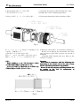
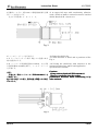
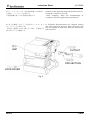
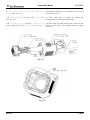
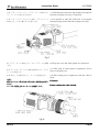
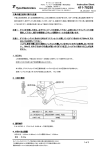
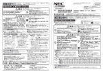
411-78262
Instruction Sheet
取扱説明書
21FEB08 Rev. A
Multiple Enclosure Connector (マルチプル エンクロージャ コネクタ)
D1100 24Pos. Rec. Type
1. はじめに
この取扱説明書は マルチ・エンクロージャ・コネク
タの組立手順、取扱方法を説明するものです。作業の
前に必ずお読みください。
1. Introduction
This manual describes the assembly procedure and
handling of the Multi Enclosure Connector. Read
this manual thoroughly before assemble/use the
connector.
2. 適用製品
2. Applicable Products
Part No.(型番)
Descriptions (名称)
1939847-1
Plug Case Assy (プラグ ケース Assy)
1939850-1
Rec. Hsg Assy (リセ ハウジング Assy)
1939851-1
Shield Clip (シールド クリップ)
1827569-2(S Reel)
D-1000 Receptacle Contact (リセプタクル コンタクト)
1827570-2(M Reel)
1827586-2(S L/P)
1827587-2(M L/P)
3. 適用ケーブル
製品規格、取付適用規格も参照してください。
電線サイズ: #30-28 AWG(D1000 S Contact)
#28-22 AWG(D1000 M Contact)
ジャケット外径: 10.0~11.0 mm
4. 関連規格
108-78417
114-5377
114-5422
411-78273
: 製品規格
: D-1 コンタクト取付適用規格
: シールド・クリップ取付適用規格
: ハンドツール取扱説明書
3. Applicable Cable
Refer Product Specification
Specification for details.
and
Application
Wire conductor size : #30-28 AWG(D1000 S Contact)
#28-22 AWG(D1000 M Contact)
Cable Jacket Outside Diameter : 10.0-11.0 mm
4. Related Documents
108-78417 : Product Specification
114-5377 : D-1 Contact Application Specification
114-5422 : Shield Clip Application Specification
411-78273 : Hand Tool Inspection Sheet
タイコ エレクトロニクス アンプ株式会社 (〒213-8535 川崎市高津区久本 3-5-8)
1 of
Tyco Electronics Corporation (3-5-8 Hisamoto Takatsu-ku Kawasaki, 213-8535)
この文書の改版の確認は本社、支店へお問い合わせください。 This document is subject to change. Call local AMP for the latest revision.
© Copyright 2008 by Tyco Electronics Corporation All rights reserved.
* : 商標 Trademark
6
Instruction Sheet
411-78262
5. D1100 24Pos. Rec.タイプ組立手順
下記の手順で組み立てます。
5. Assembly Procedure for D1100 24Pos. Rec. Type
Assemble the cable in following procedure:
1) Fig.1 を参照して、ケーブルに部品を通す。
1) Pass parts through the cable referring to Fig.1.
Fig. 1
2) ケーブルジャケットを Fig.2 に示す標準的な寸法 2) Strip the cable jacket in accordance with Fig. 2.
Do not cut or damage the wires/cable. Cut cable
を参考に、被覆剥きする。
end and retry if the cable or wires are cut off or
芯線に傷をつけない様に注意する事。
傷がつく、または一部が切断した場合はやり直す。 damaged.
A braided shield should turn up a Fig.2 on the
編組シールドは、ジャケットの外側に折り返す。
outside of a jacket.
注意:
注意:
使用する
使用する電線
する電線によっては
電線によっては、
によっては、下記寸法で
下記寸法で施工した
施工した場合
した場合
でも製品性能上問題
でも製品性能上問題になる
製品性能上問題になる場合
になる場合があります
場合があります。
があります。
本コネクタの
コネクタの施工をご
施工をご検討
をご検討の
検討の際には、
には、お手数でも
手数でも必
でも必
ず弊社営業窓口にお
弊社営業窓口にお問
にお問い合わせください。
わせください。
Cautions:
Even when it constructs with the following size
depending on the electric wire to be used, it may
may
become a product performance top problem.
Be sure to ask our company operating window also
by trouble in the case of examination of
construction connector.
Fig. 2
Rev. A
2 of 6
Instruction Sheet
411-78262
3) 編組シールドに、幅6mm の導電性粘着材付き銅 3) A copper foil tape with conductivity adhesive
with a width of 6mm is twisted around a braided
箔テープを巻き付ける。
shield. Result O.D. Φ10.8-11.2.
仕上がり外径Φ10.8~11.2。
Fig. 3
4) Crimp the shield-clip.
4) シールド・クリップを圧着する。
4-1) ケーブルジャケット端が Fig. 4 の位置に来る 4-1) The direction is noted and it positions it like
Fig. 4.
様に位置決めする。
4-2) ハンドツール取扱説明書(411-78273)、および取 4-2) Crimp the shield-clip with reference to the
付適用規格(114-5422)を参照し、シールド・クリップ instruction sheet(411-78273) and application
specification(114-5422).
を圧着する。
Cautions:
注意:
注意:
Crimp with our hand tool (P/N:1891820(P/N:1891820-1).
圧着には
圧着には、
には、弊社ハンドツール
弊社ハンドツール(
ハンドツール(P/N:1891820P/N:1891820-1)を There is a possibility that the product
ご使用下さい
使用下さい。
さい。
performance decreases when constructing it by
他の方法で
方法で施工した
施工した場合
した場合、
場合、製品性能上問題になる
製品性能上問題になる場合
になる場合 other methods.
があります。
があります。
Fig. 4
Rev. A
3 of 6
Instruction Sheet
411-78262
5) D-1コンタクトは、取付適用規格(114-5377) 5) Refer to the Application Specification(114-5377),
Crimp D-1 contact to the wire.
を参照し、コンタクトを圧着する。
After crimping, check the workmanship in
圧着後規格に従って圧着状態を検査する。
accordance with the application specification.
6) 向きを確認しながら、圧着済みコンタクトをリ
セ・ハウジングに挿入する。
挿入後、電線を1本ずつ軽く引っ張り、圧着端子が
抜け出ないことを確認する。
GAP
6) Verifying direction,insert the crimped contact
into the receptacle housing. After insertion, pull
the wire lightly to make sure that the contacts are
fully inserted.
CUTOUT
PROJECTION
LOCK LEVER
Fig. 5
Rev. A
4 of 6
Instruction Sheet
411-78262
7) リセ・ハウジングとシールド・クリップをプラグ・ 7) Receptacle housing and a shield clip are stored
in a plug case assy.
ケース Assy に収める。
7-1) リセ・ハウジングの方向性に注意して、ケーブル 7-1) The cable side is drawn in noting the
directionality of the receptacle housing.
側を引き込む。
7-2) シールド・クリップの引掛部が、プラグ・ケース 7-2) The cable is pulled until do the contact of the
Assy の底面部に接するまで、ケーブルを引き込む。 hook of shield clip at the bottom surface of plug
case assy.
Fig. 6-1
Fig. 6-2
Rev. A
5 of 6
Instruction Sheet
411-78262
7-3) リセ・ハウジングと、プラグ・ケース Assy のロ 7-3) The direction with the logo marks of receptacle
housing and plug case assy is matched.
ゴ・マークとの向きを合わせる。
7-4) リセ・ハウジングのロック部が、プラグ・ケース 7-4) It pushes it until the lock lever of receptacle
housing hangs in the lock hole of plug case Assy.
Assy のロック穴に掛かるまで押し込む。
Fig. 7
8) プラグ・ケース Assy とケーブル・グランドを接続 8) Plug case assy and cable gland are connected.
する。
8-1) ケーブル・グランドの本体を締め付けて、プラグ 8-1) The body of cable gland is tightened, and it
fixes to the plug case.
ケースに固定する。
8-2) 袋ナットを締め付けて、ケーブルを固定する。
8-2) The sealing nut is tightened, and the cable is
fixed.
注意:
注意:
Cautions:
締 め 付 け トルク等
トルク 等 は 各社の
各社の 取 り 扱 い 説明書を
説明書 を 参照く
参照く
ださい。
ださい。
Please confirm the cable is fixed.
ケーブルが
ケーブルが固定されている
固定されていることを
されていることを確認
ことを確認し
確認します。
ます。
Fig. 8
Rev. A
6 of 6