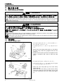
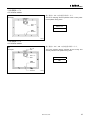
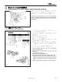
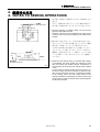
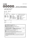
1
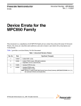
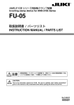
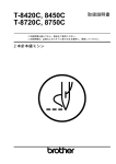
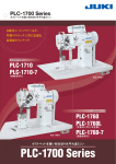
KE-435B, 435C
KE-436B, 436C
取扱説明書
INSTRUCTION MANUAL
中押え反転装置〈エアー仕様〉
この説明書を読んでから、製品をご使用ください。
この説明書は、必要なときにすぐに取り出せる場所に、保管してください。
INNER CLAMPING DEVICE〈FOR PNEUMATIC〉
Please read this manual before using the machine.
Please keep this manual within easy reach for quick reference.
KE-435C,436C
目
次
CONTENTS
1. 取り付ける前に・・・・・・......................1
1. Before installation…… ...................1
1-1. 縫製範囲.....................................................1
1-1. Sewing area ................................................1
1-2. 縫製パターンの作り方 ...............................1
1-2. How to make a sewing pattern ...................1
1-3. 送り板の作り方..........................................2
1-3. How to make the feed plate ........................2
1-4. 押え板の作り方..........................................3
1-4. How to make the work clamp plate.............3
1-5. 押え足の取り外し ......................................4
1-5. Removing the presser foot..........................4
2. 取り付け方 ...............................................5
2. INSTALLATION ....................................5
2-1. 押え関係.....................................................5
2-1. Work clamp unit ..........................................5
2-2. エアー関係 .................................................7
2-2. Pneumatic system ......................................7
2-3. 配管 ............................................................8
2-4. メモリースイッチの切り替え
2-3. Piping ..........................................................8
(KE-435B、435C) .................................9
(KE-435B, 435C) ........................................9
2-5. メモリースイッチの切り替え
(KE-436B、436C) .................................11
2-6. ディップスイッチの切り替え
2-4. Setting the memory switch
2-5. Setting the memory switch
(KE-436B, 436C) ........................................11
2-6. Setting the DIP switch
(KE-436B、436C) .................................12
(KE-436B, 436C) ........................................12
3. 調整 ..............................................................13
3. ADJUSTMENT .......................................13
3-1. 空気圧の調整..............................................13
3-1. Adjustment of air pressure..........................13
3-2. 位置決め板の調整 ......................................13
3-2. Adjustment of the positioning plates...........13
3-3. 押えクランクの水平位置調整 ....................14
3-3. Adjustment of the work clamp crank
3-4. 押え上げ速さの調整...................................15
4. 縫製時の注意 ..........................................16
horizontal position.......................................14
3-4. Adjustment of the work clamp
plate lifting speed........................................15
4. NOTES TO SEWING OPERATIONS .......16
1. 取り付ける前に・・・
1. Before installation……
1. 取り付ける前に・・・・・・
1. Before installation……
1-1. 縫製範囲
1-1. Sewing area
下記の範囲内で使用してください。
Use within the range given below.
X (mm) × Y (mm)
0001Q
最大 / Max.
100 × 60
最小 / Min.
20 × 13
※ Y が 13mm 以上 20mm 未満の場合下記のオプション部品が必要です。また、縫製パターンや送り板、押え板の作り方
が異なります。
* If Y is within the range of 13 mm up to less than 20 mm, the following optional parts will be necessary. In addition, the method
of creating the sewing pattern and the feed plate and work clamp plate will also be different.
条件 1 / Condition 1
条件 2 / Condition 2
条件 3 / Condition 3
Y が 20mm 以上 60mm 以下
Y が 16mm 以上 20mm 未満
Y が 13mm 以上 16mm 未満
Y = 20 mm to 60 mm
Y = 16 mm to less than 20 mm
Y = 13 mm to less than 16 mm
品名 / Name of Parts
Code
Code
品名/ Name of Parts
オサエクランク LA
付属品
オサエクランク S
Work clamp crank, LA
Accessory
Work clamp crank, S
154297-001
オサエイタホルダ L
付属品
オサエイタホルダ S
Work clamp plate holder, L
Accessory
Work clamp plate holder, S
154291-001
品名 / Name of Parts
オサエクランク SS
Work clamp crank, SS
オサエイタホルダ S
Work clamp plate holder, S
Code
S04516-001
154291-001
1-2. 縫製パターンの作り方
1-2. How to make a sewing pattern
[条件 1]
、
[条件 2]
縫製エリアの上端の中心(A)に、縫製パターンの上側の中心
を合わせて作ります。
[条件 3]
縫製エリアの上端の中心(A)から 3mm 下がった位置(B)に、
縫製パターンの上側の中心を合わせて作ります。
縫製パターン
Sewing pattern
※ 返し縫いの範囲については「4. 縫製時の注意」参照
縫製エリア
Sewing area
2715Q
[Condition 1 and Condition 2]
Align the center point for the top edge of the sewing pattern
with the center point (A) at the top edge of the sewing area.
[Condition 3]
Align the center point for the top edge of the sewing pattern at
point (B) 3 mm below the center point (A) at the top edge of the
sewing area.
* Refer to “4. Note to sewing operations” for details of the
reverse stitching area.
1
KE-435C,436C
1. 取り付ける前に・・・
1. Before installation……
1-3. 送り板の作り方
1-3. How to make the feed plate
2631Q
1. 送り板(1)の基準位置(C)に、縫い目の上側の中心を
合わせます。
条件 1、条件 2:a=77
条件 3:a=74
2. 縫い目より 6mm 大きくした寸法をとります。
3. 位置決め板 L(2)、R(3)の寸法をとります。
(斜線部)
4. 上記 2.と 3.を重ね合わせた形状の抜き寸法で、送り
板(1)を加工します。
※ 2.の寸法が 3.の寸法よりも大きい場合は、2.の寸
法で加工します。
縫い目
Stitch
ラベル
1. Align the center of the top edge of the seam with the
reference point (C) on the feed plate (1).
Label
Condition 1 & 2: a = 77
Condition 3: a = 74
2632Q
2. Make the dimensions 6 mm larger than the size of the
stitch.
3. Measure the size of positioning plate L (2) and
positioning plate R (3) (shaded section).
4. Make the feed plate (1) so that the size overlaps the
sizes in 2. and 3. above.
* If the size in step 2. is larger than the size in 3., then
use the size in step 2. for processing.
縫い目
Stitch
2633Q
KE-435C,436C
2
1. 取り付ける前に・・・
1. Before installation……
1-4. 押え板の作り方
1-4. How to make the work clamp plate
2634Q
条件 1
条件 2
Condition 1
Condition 2
条件 3
2636Q
Condition 3
2635Q
押え板
Work clamp
2637Q
2638Q
[条件 1]
1. 押え板のねじ穴中心より 11mm 上の位置(基準位置(D))に縫い目を合わせます。
2. 縫い目よりも 1.5mm 小さくした寸法に、押え板を加工します。
3. 押え板の菱目のない側の全周に、1mm の面取り加工をします。
[条件 2]
1. 押え板のねじ穴中心より 9mm 上の位置(基準位置(E))に縫い目を合わせます。
2. 縫い目よりも 1.5mm 小さくした寸法に、押え板を加工します。
3. 押え板の菱目のない側の全周に、1mm の面取り加工をします。
4. さらに、図のように 0.5mm の段を加工します。
[条件 3]
1. 押え板のねじ穴中心より 6mm 上の位置(基準位置(F))に縫い目を合わせます。
2. 縫い目よりも 1.0mm 小さくした寸法に、押え板を加工します。
3. 押え板の菱目のない側の全周に、1mm の面取り加工をします。
4. さらに、図のように 0.5mm の段を加工します。
[Condition 1]
1. Align the stitch with reference point (D) which is 11 mm above the center of the screw hole in the work clamp plate.
2. Make the work clamp plate so that it is 1.5 mm smaller than the size of the seam.
3. Make a 1 mm bevel all along the side of the work clamp plate that does not have a ridge line.
[Condition 2]
1. Align the stitch with reference point (E) which is 9 mm above the center of the screw hole in the work clamp plate.
2. Make the work clamp plate so that it is 1.5 mm smaller than the size of the seam.
3. Make a 1 mm bevel all along the side of the work clamp plate that does not have a ridge line.
4. Then make a step of 0.5 mm as shown in the illustration.
[Condition 3]
1. Align the stitch with reference point (F) which is 6 mm above the center of the screw hole in the work clamp plate.
2. Make the work clamp plate so that it is 1.0 mm smaller than the size of the seam.
3. Make a 1 mm bevel all along the side of the work clamp plate that does not have a ridge line.
4. Then make a step of 0.5 mm as shown in the illustration.
3
KE-435C,436C
1. 取り付ける前に・・・
1. Before installation……
1-5. 押え足の取り外し
1-5. Removing the presser foot
締ねじ(1)をゆるめて、押え足(2)を外します。
(押
え足は使用できません。)
Loosen the screw (1), and then remove the presser foot
(2).
2958Q
KE-435C,436C
4
2. 取り付け方
2. INSTALLATION
2. 取り付け方
2. INSTALLATION
危険 / DANGER
コントロールボックスのカバーを開ける時は必ず電源スイッチを切り、電源プラグを抜いて、その後 5
分間待ってからカバーを開けてください。高電圧部分にふれると、大けがをすることがあります。
Wait at least 5 minutes after turning off the power switch and disconnecting the power cord from the wall
outlet before opening the face plate of the control box. Touching areas where high voltages are present can
result in severe injury.
注意 / CAUTION
据え付けが完了するまで、電源プラグを接続しないでください。
誤ってフットスイッチを踏むと、ミシンが作動してけがの原因となります。
エアー供給源のエアーコックを閉じ、ドレインコックよりエアーを抜き、圧力計の指針を「0」にして
ください。
Do not connect the power cord until installation is complete, otherwise the machine may operate if the foot
switch is depressed by mistake, which could result in injury.
Close the air cock of the air supply source, and then open the drain cock to bleed the air until the needle of
the pressure gauge points to “0”.
2-1. 押え関係
2-1. Work clamp unit
1. 押え足押え板(1)を取り外して、押え足 434E エアー
(2)(押え(3))を取り外します。
2. 送り板(4)を取り外して、加工した送り板を取り付け
ます。
1. Remove the work clamp guide plates (1), and detach
the work clamp, 434E air (2) together with the work
clamp (3).
2. Replace the feed plate (4) with the feed plate that was
made in accordance with “How to make the feed
plate.”
2959Q
3. 押え板(5)を押え板ホルダ(6)に取り付けます。
4. 外押え足(7)と押えクランク組 434E (8)を押え腕(9)
に、押え足押え板(1)で取り付けます。
3. Attach the work clamp plate (5) to the work clamp
plate holder (6).
4 Attach the outer work clamp (7) and the work clamp
crank assy, 434E (8) to the work clamp arm (9), and
fix these components with work clamp guide plates
(1).
2960Q
5
KE-435C,436C
2. 取り付け方
2. INSTALLATION
5. 位置決め板 R(10)と位置決め板 L(11)を外押え足(7)
に取り付けます。
5. Attach the positioning plate R (10) and the positioning
plate L (11) to the outer work clamp (7).
2961Q
2-1-1. 押えクランク、押え板ホルダの交換
2-1-1. Replacing the work clamp crank and work clamp plate holder
条件 2、条件 3 の場合、押えクランクと押え板ホルダを取り替える必要があります。
For Condition 2 and Condition 3, the work clamp crank and work clamp plate holder must be replaced.
2639Q
図 1 / Fig.1
2640Q
1. 締ねじ(1)を外して、押えクランクホルダ(2)から押えクランク(3)を取り外します。
2. 締ねじ(4)を外して押え板ホルダ(5)を交換し、再度締ねじ(4)で取り付けます。
3. 押えクランク(6)を押えクランクホルダ(2)に差し込み、反転シリンダのピストンロッド(7)が引き込まれた状態
(図 1)のときに押えクランク(6)を図の向きにして、座金(8)の溝を合わせて締ねじ(1)で取り付けます。
1. Remove the screw (1), and remove the work clamp crank (3) from the work clamp crank holder (2).
2. Remove the screw (4) to replace the work clamp plate holder (5) with the optional one, and install it with the screw
(4).
3. Insert the work clamp crank (6) into the work clamp crank holder (2). Then while pulling out the reversal cylinder
piston rod (7) (Fig. 1), set the work clamp crank (6) so that it faces as shown in the illustration, align its groove with
the washer (8), and then tighten the screw (1) to secure it.
KE-435C,436C
6
2. 取り付け方
2. INSTALLATION
2-2. エアー関係
2-2. Pneumatic system
1. ベルトカバー(1)を取り外します。
(ミシンの取扱説明書参照)
1. Remove the belt cover (1).
(Refer to the Instruction Manual for the sewing
machine.)
2962Q
2965Q
2963Q
抜く
Pull out
押す
Push down
2964Q
2. コネクタ(6 個)(2)の(A)部を押し下げ、エアーチューブ(6 本)(3)を引き抜きます。
3. 電磁バルブ(3 個)(4)、コネクタ(2)、インテグレータ(5)、エアーマフラー(2 個)(6)を取り外し
ます。
4. 反転用電磁バルブ組(7)に取り外した電磁バルブ(4)、コネクタ(2)、インテグレータ(5)、エアーマフ
ラー(6)を取り付けます。
5. 反転用電磁バルブ組(7)をテーブル下面、または梁に取り付けます。(ミシンの取扱説明書参照)
2. Push down the part (A) of the six connectors (2), and pull out the six air tubes (3).
3. Remove the three solenoid valves (4), the six connectors (2), the integrator (5) and the two air mufflers (6).
4. Install the three solenoid valves (4), the six connectors (2), the integrator (5) and the two air mufflers (6) to the
reversal solenoid valve assembly (7).
5. Install the reversal solenoid valve assembly (7) to the underside of the work table or beam. (Refer to the Instruction
Manual for the sewing machine.)
7
KE-435C,436C
2. 取り付け方
2. INSTALLATION
2966Q
2967Q
0021Q
6. コントロールボックスの蓋(メイン基板取付板)を開けます。(ミシンの取扱説明書参照)
7. バルブハーネス(12P)(9)を抜きます。
8. 反転用電磁バルブ(10)のピンターミナル(11 番ピン、4 番ピン)をバルブハーネス(9)のコネクタ 11 番、4
番に差し込みます。
6. Open the control box cover (main P.C. board mounting plate). (Refer to the Instruction Manual for the sewing
machine.)
7. Disconnect the valve harness (12P) (9).
8. Insert the pin terminals (#11, #4) of the reversal solenoid valve (10) into connectors #11 and #4 on the valve
harness (9).
2-3. 配管
2-3. Piping
間欠シリンダー
Stepping cylinder
シリンダーL
Cylinder L
シリンダーR
Cylinder R
反転シリンダー
Reversal cylinder
2968Q
2969Q
1. 各々のエアーチューブを同じ番号に接続し、結束バンドで束ねます。このとき、エアーチューブをつぶさない
ようにしてください。
2. ベルトカバーを取り付けます。(ミシンの取扱説明書参照)
1. Connect air tubes in accordance with the identified numbers in the figure, and then bind them with some fastening
bands. Be sure not to crush the air tubes at that time.
2. Install the belt cover. (Refer to the Instruction Manual for the sewing machine.)
KE-435C,436C
8
2. 取り付け方
2. INSTALLATION
2-4. メモリースイッチの切り替え(KE-435B、435C)
2-4. Setting the memory switch (KE-435B, 435C)
メモリースイッチの切り替え後は、一度電源を切って、再度電源を入れ直してください。
After changing the memory switch settings, press the power switch to turn the power off and then back on again.
memo-07
ON
memo-42
05
2970Q
1. 電源スイッチを入れます。
2. テストスイッチ(1)を押しながら糸巻きスイッチ(2)を押します。
※ 表示窓(3)に[00 - -]が表示されます。
3. 表示設定スイッチ(4)を押して、表示窓(3)の左側 2 桁を[07]に合わせます。
4. 糸巻きスイッチ(2)を押して、表示窓(3)の右側 2 桁を[- -→ON]に切り替えます。
5. 表示設定スイッチ(4)を押して、表示窓(3)の左側 2 桁を[42]に合わせます。
6. ユーザープログラムスイッチ(P2、P4)(5)で、表示窓(3)の右側 2 桁を[05]に合わせます。
7. テストスイッチ(1)を押します。
※ 通常の表示に戻ります。
8. 必要に応じて次の設定を行ないます。
1. Turn on the power switch.
2. While pressing the TEST switch (1), press the BOBBIN. WIND switch (2).
* “ 00 - - “ will appear in the display window (3).
3. Press the DISPLAY SET switches (4) so that “07” appears in the two left columns of the window (3).
4. Press the BOBBIN. WIND switch (2) until the two right columns in the window (3) change from “- -“ to “ON”.
5. Press the DISPLAY SET switches (4) so that “42” appears in the two left columns of the window (3).
6. Press the user program switches (P2 or P4) (5) so that “05” appears in the two right columns of the window (3).
7. Press the TEST switch (1).
* The display will return to normal.
8. Make the following settings if necessary.
9
KE-435C,436C
2. 取り付け方
2. INSTALLATION
<1/2 反転モード>
<1/2 reverse mode>
縫い模様の 1/2 で反転装置が動作します。
例
Example
The inner clamping device operates at the 1/2-way mark
for the pattern being sewn.
スタート
Start
memo-13
-
反転
Reverse
0025Q
<1/4 反転モード>
<1/4 reverse mode>
例
Example
縫い模様の 1/4 と 3/4 で反転装置が動作します。
エンド
The inner clamping device operates at the 1/4-way and
3/4-way marks for the pattern being sewn.
End
スタート
Start
memo-13
ON
反転
Reverse
反転
Reverse
0026Q
KE-435C,436C
10
2. 取り付け方
2. INSTALLATION
2-5. メモリースイッチの切り替え(KE-436B、436C)
2-5. Setting the memory switch (KE-436B, 436C)
メモリースイッチの切り替え後は、一度電源を切って、再度電源を入れ直してください。
After changing the memory switch settings, press the power switch to turn the power off and then back on again.
memo-3b
05
2971Q
1.
2.
3.
4.
電源スイッチを入れます。
テストスイッチ(1)を押しながらステップバックスイッチ(2)を押して設定モードに入ります。
プログラム選択スイッチ(3)を押して、プログラム No.表示窓(4)を[3b]に合わせます。
ステップバックスイッチ(2)を押しながらロータリースイッチ(5)を回し、表示窓(6)を[05]に合わせ
ます。
5. テストスイッチ(1)を押します。
※ 通常の表示に戻ります。
6. 必要に応じて次の設定を行ないます。
1.
2.
3.
4.
5.
Turn on the power switch.
While pressing the TEST switch (1), press the STEP BACK switch (2) to switch to setting mode.
Press the program select switch (3) so that “3b” appears in the PROGRAM No. display (4).
While pressing the STEP BACK switch (2), turn the dial (5) so that “05” appears in the display screen (6).
Press the TEST switch (1).
* The display will return to normal.
6. Make the following settings if necessary.
11
KE-435C,436C
2. 取り付け方
2. INSTALLATION
<1/2 反転モード>
<1/2 reverse mode>
例
Example
縫い模様の 1/2 で反転装置が動作します。
The inner clamping device operates at the 1/2-way mark
for the pattern being sewn.
スタート
Start
memo-08
-
反転
Reverse
0025Q
<1/4 反転モード>
<1/4 reverse mode>
例
Example
縫い模様の 1/4 と 3/4 で反転装置が動作します。
エンド
End
The inner clamping device operates at the 1/4-way and
3/4-way marks for the pattern being sewn.
スタート
Start
memo-08
ON
反転
Reverse
反転
Reverse
0026Q
2-6. ディップスイッチの切り替え(KE-436B、436C)
2-6. Setting the DIP switch (KE-436B, 436C)
(ご注意)
ディップスイッチの変更の際には、必ず電源を切っ
てください。
ディップスイッチ A の No.6 を“ON”にします。
※ 反転装置を使用しないときは、ディップスイッチ A
の No.6 を“OFF”にしてください。
Note: Be sure to turn off the power before changing any
of the DIP switch settings.
Turn the selector No.6 on the DIP switch A to “ON”.
* When the inner clamping device is not used, turn the
selector No.6 on the DIP switch to “OFF”.
1086Q
KE-435C,436C
12
3. 調整
3. ADJUSTMENT
3. 調整
3. ADJUSTMENT
3-1. 空気圧の調整
3-1. Adjustment of air pressure
2972Q
高くなる
Increase pressure
高くなる
Increase pressure
2622Q
1. 空気圧は 0.5Mpa で使用してください。
インテグレータ(1)のハンドル(2)を引き上げてから回
して調整します。
調整終了後はハンドル(2)を下へ押してロックします。
2. 反転用シリンダの空気圧は、押え板(3)で縫製物を押え
たときに押えクランク(4)が反転する範囲内にします。
(0.3Mpa 程度)
エアーレギュレータ(5)のハンドル(6)を引き上げてか
ら回して調整します。
調整終了後はハンドル(6)を下へ押してロックします。
3. インテグレータ(1)のボルト内に水がたまったら、ドレ
インコック(7)を矢印の方向に回して水を抜きます。
1. Air pressure should be 0.5 Mpa.
The air pressure can be adjusted by pulling up and
turning the control knob (2) on the integrator (1).
After adjustment is complete, push the control knob (2)
downward to lock it.
2. Adjust the air pressure for the reversal cylinder to stay
within such a range that the presser crank (4) rotates
reversely when pressing the sewing material with the
work clamp plate (3). (Approx. 0.3 Mpa)
For adjustment, pull up and, turn the control knob (6) on
the air regulator (5).
After adjustment is complete, push the control knob (6)
downward to lock it.
3. If water stands in the bottle of the integrator (1), turn the
drain cock (7) in the direction indicated by an arrow to
drain the water.
3-2. 位置決め板の調整
3-2. Adjustment of the positioning plates
縫い目(A)がラベル(1)に対して、前後方向が均等にな
るように、締ねじ(2)をゆるめて位置決め板 R(3)で調整し
ます。
また、左右方向は縫い目(B)が均等になるように、締ね
じ(4)をゆるめて位置決め板 L(5)で調整します。
Loosen the screws (2), and adjust the position of the
positioning plate R (3) so that the label (1) can be evenly
laid out between the front and back seams (A).
Next, loosen the screws (4), and adjust the position of the
positioning plate L (5) so that the presser plate can be
evenly laid out between the left and right seams (B).
2623Q
13
KE-435C,436C
3. 調整
3. ADJUSTMENT
3-3. 押えクランクの水平位置調整
3-3. Adjustment of the work clamp crank horizontal position
反転シリンダのピストンロッド(1)を左へいっぱい出し
たとき、押えクランク(2)が水平になるように、ナット
(3)をゆるめ、ボルト(4)を出し入れして調整します。
Loosen the nut (3) and push in or pull out the adjusting
bolt (4) so that the work clamp crank (2) can be horizontal
when the reversal cylinder piston rod (1) is moved to the
left extreme.
2624Q
3-3-1. 確認(KE-436B、436C)
3-3-1. Verification (KE-436B, 436C)
2973Q
1. メニュースイッチ(1)を押して、下糸カウンターラ
ンプ(2)を点灯させます。
2. テストスイッチ(3)を押しながら読/書スイッチ(4)
を押します。
※ 表示が(
)となります。
3. 押えスイッチ(5)を踏みます。
押えスイッチ(5)を踏むごとに、押えクランク(6)
が左右に反転をくり返します。
※ 押えクランク(6)が、押え板(7)と位置決め
板 R(8)に当たっていないことを確かめてくだ
さい。
4. テストスイッチ(3)を押すと解除されます。
1. Press the MENU switch (1) until the B.T. COUNTER
indicator (2) illuminates.
2. While pressing the TEST switch (3), press the R/W
switch (4).
.
* The indicator shows
3. Depress the work clamp switch (5).
Verify that whenever the work clamp switch (5) is
depressed, the work clamp crank (6) flips left or right.
* Make sure that the work clamp crank (6) does not hit
the work clamp plate (7) and the positioning plate R
(8).
4. Press the TEST switch (3) again to end the test mode.
2974Q
2975Q
KE-435C,436C
14
3. 調整
3. ADJUSTMENT
3-4. 押え上げ速さの調整
3-4. Adjustment of the work clamp plate lifting speed
電磁バルブの排気絞り弁のナット(1)をゆるめ、調節ね
じ(2)を回して行います。
上側の排気絞り弁は押えが上がるときの速さを、下側
の排気絞り弁は押えが下がるときの速さを調整します。
・ 電磁バルブ(3)・・・・・・押え板用
・ 電磁バルブ(4)・・・・・・位置決め板用
速くなる
Faster
遅くなる
Slower
2976Q
15
Loosen the nut (1) on the exhaust air throttle valve for the
solenoid valve, and turn the adjusting screw (2) to adjust
the work clamp plate lifting speed.
The upper exhaust air throttle valve adjusts the work
clamp plate ascending speed, while the lower exhaust air
throttle valve adjusts the descending speed.
• Solenoid valve (3)……for the work clamp plate
• Solenoid valve (4)……for the positioning plates
KE-435C,436C
4. 縫製時の注意
4. NOTES TO SEWING OPERATIONS
4. 縫製時の注意
4. NOTES TO SEWING OPERATIONS
0032Q
基準点
Reference point
4.5mm
1. 返し縫いの範囲は、基準点より左右に 4.5mm まで可
能です。
ただし、標準以外の押えクランクをご使用の場合は、
返し縫いの範囲が狭くなりますのでご注意ください。
4.5mm
1. Reverse stitching is possible within 4.5 mm left and
right from the reference point.
However, note that if a non-standard work clamp crank
is being used, the reverse stitching area will become
smaller.
2. 縫い終わり後に押えクランク(1)が反転する時、針と
当たらないように押えを待避させていますが、縫製
物が薄いと待避しなくてもよい場合があります。
その時は、memo-15 を ON にすると待避しなくなり、
サイクルタイムが速くなります。ただしこの時には、
縫製終了位置で押えクランクを動かし(エアーを抜
いて手で動かします)、針と当たらないことを確認し
てください。
上がる
Lift
布の厚み
Thickness of material
2630Q
2. When the work clamp crank (1) reverses after sewing
is completed, the work clamps are retracted so that
they do not touch the needle. However, sometimes it is
not necessary to retract the work clamps if the material
is thin.
In such cases, if memory switch memo-15 is set to on,
the work clamps will not be retracted so that the cycle
time can be shortened. However, if making this change
to the setting, move the work clamp crank to the
sewing end position (release the air and move the work
clamp crank by hand) to check that the work clamps do
not touch the needle.
KE-435C,436C
16
取扱説明書
INSTRUCTION MANUAL
15-1, Naeshiro-cho, Mizuho-ku, Nagoya 467-8561, Japan. Phone: 81-52-824-2177
Printed in Japan
118-P34
S91P34-021
2002.12.B(1)