1
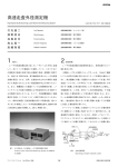
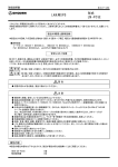
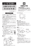
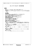
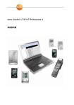
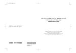
DMGシリーズ
(ロギング機能付)
取扱説明書
東 京 支 店 〒105-0004 東京都港区新橋2-21-1・新橋駅前2号ビル
大 阪 営 業 所 〒532-0033 大 阪 市 淀 川 区 新 高 1 - 1 0 - 9
}
● 太陽の直射が伝送窓部に入射する所。
取付け、配線工事、操作を行う前に取扱説明書などをよくお読みの
上、正しくご使用ください。また必要に応じて取扱説明書などが最
終の使用責任者の手元に届くよう、ご配慮願います。
取扱いを誤った場合に、中低度の障害や軽傷
を受ける恐れ、あるいは物損障害が発生する恐
れがあります。また、状況によっては重大な結
果に結びつく恐れがあります。
この商品は安全用として設計されたものではありません。安全
用として使用される場合や、この商品が万一故障したとき重大
な影響が予測される用途に使用される場合は、その危険性に
応じて保守・点検の頻度を増したり、またはバックアップ回路
を併用する等の措置を行ってください。
● 商品は、本体あるいはカタログ等に記載の電圧及び電流で使
用してください。定格外の使用は、短絡・火災などの恐れが
あります。
● 商品を廃棄する場合は、産業廃棄物として取り扱ってください。
隣接した高周波点灯蛍光灯の光が、本装置の指向角内に入る所
(GOが落ちることがあります)。
● その他、定格を超える温度
(−10∼+50℃以外)、湿度、振動、
衝撃などが加わる所。
●
● 外形は図-1の通りです。
● 伝送エリアは図-2を参照してください。
●
■外形図
動
作
幅
Y
(cm)
エリア1:伝送距離0∼1m
エリア2:伝送距離0∼3m
2.5
投光ボリューム
(光軸方向)
10
3
28
50
50
42
4
100
200
300
400
500
(14.5)
サイドオン
リード線
ヘッドオン
● 出力部(共通)
+VIN 330 Ω
3. 3kΩ
+5V
+5V
IN
R
表示灯
1/ 4W
OUT
表示灯
COM
COM
ON電流2. 5mA以上、
NPNオープンコレクタ出力
OF F電流1mA 以下
DC30 V 50m A残留電圧1.8V以下
2線 式センサは使用できません。
(動作スレッショルド電流1. 5∼ 2m A)
図-3
■調整
距 離 X (cm)
通信エリアの端部では不安定動作となります。そのため、出力が
ON/OFF(チャタリング)することがあります。
(1)入・出力部及び各リード線の仕様は図-3の通りです。
(64.5)
注)使用しない入出力及びGO出力、セレクト入力、モード入力の端末処理
はそれぞれの単独処理とし、他のリード線とは接続しないようにしてく
ださい。一括処理されますと動作不安定の原因となります。
注)ケーブルに付属しているコネクタは、中継端子としては使用できません。
注)COMと−VINは、内部でショートされています。
エリア1
■接続
20
光信号が正しく受信されていることを確認するためのもので、
● 光信号受信時ON
となります。
● 光路遮断時(非受信時)OFF
エリア2
図- 2
●
}
● 入力部(共通)
■伝送エリア
(代表例)
30
φ20 2-φ4.5
取付にはM4ネジを用いて、振動等で緩まないよう、しっかりと固
定してください。尚、締付トルクは1N・m(約10kg・cm)以内とし
てください。
60
50
40
30
20
10
0
10
20
30
40
50
60
外部信号により任意に送受信動作を停止させるためのもので、
● セレクト←→入出力COM間オープンで動作
となります。
● セレクト←→入出力COM間ショートで動作停止
※3. GO出力
}
(2)取付方法
●
30
※1. モード入力
待機時の送受信モードを選択するためのもので、
● モード←→入出力COM間オープンで送信待機モード
となります。
● モード←→入出力COM間ショートで受信待機モード
※2. セレクト入力
(ログデータ読み出し時は解除)
● 有機溶剤の蒸気や腐食性ガスのある所。
安全上のご注意
伝送窓
☎ (06)6394-2102代
URL http://www.hokuyo-aut.co.jp
No. MFA-0042C 0702
注意
☎ (03)3572-2846代
名古屋営業所 〒450-0002 名古屋市中村区名駅4-8-12・菱信ビル ☎ (052)582-4641代
コ ネ ク タ( 2 )
コ ネ ク タ(1)
仕 様
仕 様
リード線(色)ピンNo.
リード線(色)ピンNo.
IN5
水
緑
1
1
COM(0V)
2
緑/黒
桃
2
モード※1
OUT5
青
IN6
白
セレクト※2
3
3
青/黒
4
4
白/黒
GO※3
OUT6
紫
茶
5
5
IN1
IN7
6
紫/黒
OUT7
6
茶/黒
OUT1
赤
灰
7
7
IN2
IN8
8
OUT8
赤/黒
灰/黒
8
OUT2
橙
桃/黒
9
+VIN
9
IN3
水/黒
橙/黒
10
−VIN
10
OUT3
黄
シールド
シールド
11
IN4
12
黄/黒
OUT4
(2)動力線や高圧線との並行配線や同一配管は避けてください。
(3)本商品の基準リード線長は2mです。延長される場合は同様のシー
ルド線を使用してください。尚、リード線の端末に付いているコ
ネクタは、中継端子として使用できませんので注意してください。
(1)本商品に装備しています表示灯は図-4の通りです。
(2)調整は通電状態で行います。電源表示灯
(POW)が点灯している
ことを確認してください。
(3)光軸調整
● 伝送窓部を目視で対向させ、仮止めします。
● 次にその状態で上下・左右に動かしてGO出力表示灯
(GO)の点
灯している範囲を確認し、その中央に固定します。相手方も同様
に調整します。
● 投光ボリュームにより、伝送距離を可変することができます。
■取付け
(1)次のような場所での使用は避けてください。
● 伝送窓部に水や油の飛沫がかかる所
(本商品の保護構造はIP64
ですが、伝送窓部に水滴や油がつくと性能を低下させます)。
(2)光通信データのロギング機能
ロギング機能とは、例えばアクティブ装置
(台車側)とパッシブ装置
(装
置側)
との間で、一連の動作手続
(シーケンス)
を行うような場合にお
いて、光送受信データ及びセレクト入力・GO出力の変化をトリガー
として、光送受信データ及びGO、セレクトと光受信データの不変時
間を不揮発性メモリに随時記録します注1)。
(3)光通信ログ仕様
注2)
デ ー タ の 変 化 回 数
100回以下
記
光送受信データ、各8BIT
GO出力
セレクト入力
注3)
電源
憶
デ
ー
タ
不変時間の計測単位
0.05s
不変時間の計測誤差
±0.05s
不変時間の計測範囲
1638.35s(約27分)以下
記
体
強誘電体メモリ(512バイト)
ル
20ms以上
憶
記
憶
記
サ
憶
媒
イ
寿
ク
命
注4)
コネクタ(1 ) 12P
(日圧PHR-12 )
コネクタ(2 ) 10P
(日圧PHR-10 )
シールド
10
記憶回数
10 回
記憶年数
10年
注1)監視・記憶するのは、光送受信データです。入出力データとは異なる場
合があります。
注2)データの変化回数が最大値を超えた場合は、古いデータから順に上書
きしていきます。
注3)電源OFFのときは、記憶データ全てON状態を1秒間記憶します。
注4)光送受信データ不変時間の計測が最大値を超えた場合は、最大値とし
て記録します。
(4)ロギングデータの読み出し方法
インターロック等のトラブル発生時には、記憶していたデータを光
リモコン式データトランスファーチェッカー
(別売り:BNC-HB1)を用
いて読み出し、専用のアプリケーションソフトによりパソコンで表
示することができます。
読み出しも光通信で行いますので、機台のカバーを外すことなく容
易に行えます。光リモコン式データトランスファーチェッカーのヘッ
ドをロギング機能付光データ伝送装置の送受信窓にあてるように
して行えます。
ただし、読み出し時は必ずセレクト入力を解除
(オープンまたは+
VIN)し、アクティブ状態にして行ってください。
注 意 設定等、詳細については専用の光リモコン式データトランスファーチェッ
カーユニットの仕様書、及びデータトランスファーチェッカー付属のアプリ
ケーションソフト
(SFOC)のHELPをご覧ください。
データトランスファーチェッカー
DMG
ヘッド
②入力データ表示灯
電源BOX
使用に際しては、必ず自己側と相手側のモードが逆になるように設定してくだ
さい
(自己側を送信待機モードとする場合、相手側は必ず受信待機モードとし
てください)。
リード線
(1)概要
入出力データを記憶する機能
(ロギング)を装備していますので、
トラブル時の解析に威力を発揮します。また標準品
(DM・DMSシ
リーズ)とも光通信、入出力に互換性がありますので、既設ライン
への置き換えが可能です。
図-4
①出力データ表示灯
注 意 待機モードについて
(モード入力で切り換え)
図-1
■ロギング機能の説明
OUT
ACアダプタ
IN
PC
GO
③GO出力表示灯
POW
ログデータ読み込み用スイッチ
④電源表示灯
①出力データ表示灯
(OUT):出力時それぞれ点灯
②入力データ表示灯
(IN):入力時それぞれ点灯
③GO出力表示灯
(GO):GO出力ON時点灯
④電源表示灯
(POW):通電時点灯
ログデータの読み込みは、パソコンを接続しなくてもログデータ読
み込み用スイッチにより読み込むことができます。
データトランスファーチ
ヘッド
DATA TRANSMISSION DEVICE
DMG series
(with Logging Function)
INSTRUCTION MANUAL
1-10-9, NIITAKA, YODOGAWA-KU, OSAKA 532-0033, JAPAN
TEL:+81-6-6394-2102 FAX:+81-6-6394-2339
URL :http://www.hokuyo-aut.jp
No. MFA-0042C
● Solvent
NOTICE FOR SAFETY
Please be sure to handle and operate the products correctly according
to the Instruction Manual etc. before making installation, wiring, operation and/or maintenance of the products. If necessary, arrange to
reach the Instruction Manual etc. to final responsible person.
WARNING
Possible to cause medium damage and
slight injury, or physical damage when misused. However it is possible to cause more
serious result according to situation.
This product is not designed for safety measures. If this
is intended to be used for safety purpose or a usage which
will expect to be affected serious damage when this product
would malfunction, please be sure to take measures such as
increasing maintenance frequency or having back-up circuit on
it according to its degree of danger.
● This product should be used under the voltage and current
mentioned on the product or the brochure. It is possible to
occur short circuit or fire if it is used out of rated value.
● When abandon, please treat it as industrial waste.
●
■EXTERNAL DIMENSIONS
2- φ4.5
(2) Installation
● Dimension is as per Fig.1.
● Refer to Fig.2 for transmitting area.
● Tighten firmly with M4 screw in order to be not loosen by vibration etc. Tighten torque of screw should be less than 1N・m.
(Approx. 10kg・cm)
■TRANSMISSION AREA (typical example)
60
50
40
30
20
Operation 10
width
0
Y
10
(cm)
20
30
40
50
60
Area 1:Transmission distance 0∼1m
Area 2:Transmission distance 0∼3m
30
●
2. 5
10 3
28
50
(64.5)
Projection
amount adjuster
Optical axis direction
4
(14. 5)
Side-on
Lead wire
100
20 0
300
400
Fig. 1
section(common)
+VIN 330Ω
3.3kΩ
● OUTPUT
+5V
IN
R
Pilot lamp
1/4W
OUT
COM
COM
ON current : 2.5mA or more,
OFF current: 1mA or less
2-wire type sensor can't be used.
(operation threshold current:1.5∼2mA)
NPN open-collector output
30VDC 50mA
Residual voltage 1.8V or less
Fig. 3
Distance X (cm)
Operation is unstable around the end part of communication
area and output may be chattering.
(1) The specifications of input/output and lead wire are as per Fig. 3.
(2) Refrain from wiring parallel or in same conduit with power
source or high voltage line.
(3) The standard wire length is 2m provided. Use the same shield
line when extend the length more.
When operate, set each device in reverse mode between transmission
side and reception side. (When the transmission side is set Transmitstandby mode, the reception side must be set Reception-standby mode).
lead wire
section(common)
500
NOTE About standby mode (changeover by MODE input)
Head-on
● INPUT
Pilot
lamp
■CONNECTION
20
Note) Terminal ends handling of not using input, output, GO output, SELECT
input, MODE input and are to be treated individually and not touching
to the other lead wires. If handled in one treatment, it will cause
malfunction.
Note) The connector attached on the end of lead wire can not be used as
connecting terminal.
Note) COM and -VIN are shorted internally.
+5V
Area 1
Connector(2)
Lead wire (Color) Pin No.
Spec.
Green
1
IN5
Green/Black
2
OUT5
Blue
3
IN6
Blue/Black
4
OUT6
Purple
5
IN7
Purple/Black
6
OUT7
Gray
7
IN8
Gray/Black
8
OUT8
Pink/Black
9
+VIN
L.Blue/Black
10
−VIN
Shield
Shield
※1. Mode input
This is to select transmission or reception standby mode.
● Transmission standby mode when it is opened between MODE & I/O COM.
● Reception standby mode when it is short circuited between MODE & I/O
COM.
※2. Select input
This is to stop transmission & reception operation by outside signal.
● Operates when it is opened between SELECT & I/O COM.
● Stops operation when it is short circuited between SELECT & I/O COM.
(must be opened when reading logging data)
※3. GO output
This is to check for correct reception of optical signal.
● It is ON when optical signal is received.
● It is OFF when optical signal is interrupted (or non-receiving state).
Area 2
F ig. 2
42
50
30
φ20 Transmission window
gas & corrosive gas exist.
sunlight put into the light transmitting windows.
● Any places where the light enters into directional angles of this
device if using it near high-frequency fluorescent lamp (Go
signal may be down).
● Any places suffered with over-rated temperature (except -10∼
+50℃ ), humidity, vibration & shock etc.
● Direct
Connector(1)
Lead wire (Color) Pin No.
Spec.
Light blue
1
COM(0V)
Pink
2
MODE※1
White
3
SELECT※2
White/Black
4
GO※3
Brown
5
IN1
Brown/Black
6
OUT1
Red
7
IN2
Red/Black
8
OUT2
Orange
9
IN3
Orange/Black
10
OUT3
Yellow
11
IN4
Yellow/Black
12
OUT4
12P connector(1)
■ADJUSTMENT
(1) Indication lamps provided for the system are as shown in Fig.4.
(2) Adjustment is made during energizing. Confirm the power lamp
(POW) is lit up.
(3) Optical axis adjustment
● Make the transmission windows of the units face to each other
visually and fix them temporarily.
● With the state retained, move one of them vertically and horizontally to confirm the effective lighting ranges of the output
lamp (GO) and fix to the center of the range.
Execute the same adjustment for the other unit.
● It is possible to change the transmission distance by projection
amount adjuster.
① Output data lamp (OUT)
② Input data lamp (IN)
③ GO output lamp (GO)
④ Power lamp (POW)
: Lights up when output
: Lights up when input
: Lights up when Go output is ON
: Lights up when energizing
■LOGGING FUNCTIONS
(1) General
This device provides with logging function which memorizes
I/O data and this function is very helpful to analyze when troubles such as interlocking etc. happened. Also, this device is compatible with standard models, DMS-HB1/GB1 series under the
circumstances such as optical communication, input/output and
installation and so it is easy to replace them at the current facilities.
(2) Logging functions
This device memorizes transmission/reception data, GO,
SELECT and invariable time of reception data in non-volatile
storage in all time by using changes of transmission/reception
Note 1)
data, SELECT input and GO output as trigger.
(3) Specifications
Max. 100 times or less Note 2)
Transmission/reception data : Each 8 bits,
GO output, SELECT input, Power Note 4)
Data variable time
Memorizing data
Measuring unit of
invariable time
Measuring error of
invariable time
Measuring range of
invariable time
Memorizing media
0.05sec
±0.05sec
Max.1638.35sec (Approx. 27min.)
Ferroelectric memory (512 byte)
Min. 20msec
Memorizing cycle
Memorizing life
Nos.
1010 times
Years
10 years
Note 1) Transmission/reception data is monitored and memorized. It may be
different with input/output data.
Note 2) In case that data variable Nos. exceed max. value, it is overwritten from
older data.
Note 3) In case that measuring of invariable data for transmission/reception data
exceeds max. value, it is Memorized as max. value.
Note 4) When OFF, ON state for all memorized data is memorized for 1 sec.
(4) How to read-out
When some troubles such as interlocking etc. happened, you can
read out memorized data with data transfer checker (Optical remote
controller, option) and show them on PC with exclusive application
software. It is easy to read out without removing cover because
of reading out by optical communication. It is made by facing
the head of data transfer checker(Optical remote controller) to
transmission/reception part of DMG.
Please note that don't use SELECT input. (Please open or
connect to +VIN)
NOTE Please see the specifications sheet for optical remote control type
data transfer checker and HELP of application software attached to
data transfer checker in details.
Data Transfer checker
DMG
Head
Power box
Fig. 4
①Output data lamp
②Input data lam p
OUT
IN
GO
POW
AC adaptor
PC
■INSTALLATION
(1) Please don't use at the following places:● Water & oil splashes on the light transmitting windows. (The
protective structure of this product is IP64, but if water or oil
splashes on the light transmitting windows, performance of the
products will be lowered.)
Note 3)
Switch for data read-out
10P connector(2)
shield
③GO ou tput lamp
④Power lamp
It can be read-out by pushing the switch for data read-out even if not
connecting to PC.
データトランスファーチ