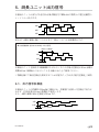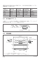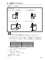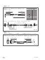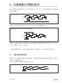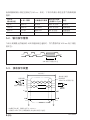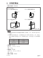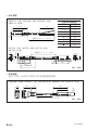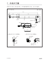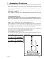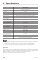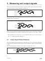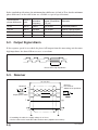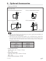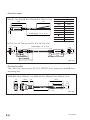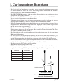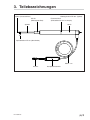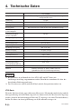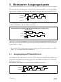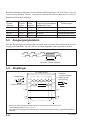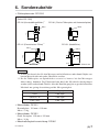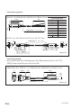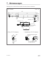
1
デジタルゲージ /
/ Digital Gauge / Digitale Messtaster
DK110NLR5
お買い上げいただき、ありがとうございます。
ご使用の前に、この取扱説明書を必ずお読みください。
ご使用に際しては、この取扱説明書どおりお使いください。
お読みになった後は、後日お役に立つこともございますので、必ず保管してください。
Read all the instructions in the manual carefully before use and strictly follow them.
Keep the manual for future references.
Lesen Sie die ganze Anleitung vor dem Betrieb aufmerksam durch und folgen Sie
beim Betrieb des Geräts den Anweisungen. Bewahren Sie diese Bedienungsanleitung
zum späferen Nachlesen griffbereit auf.
取扱説明書 / 使用说明书 / Instruction Manual /
Bedienungsanleitung
[For U.S.A. and Canada]
THIS CLASS A DIGITAL DEVICE COMPLIES WITH PART15 OF THE
FCC RULES AND THE CANADIAN ICES-003. OPERATION IS
SUBJECT TO THE FOLLOWING TWO CONDITIONS.
(1) THIS DEVICE MAY NOT CAUSE HARMFUL INTERFERENCE, AND
(2) THIS DEVICE MUST ACCEPT ANY INTERFERENCE RECEIVED,
INCLUDING INTERFERENCE THAT MAY CAUSE UNDERSIGNED
OPERATION.
CET APPAREIL NUMÉRIQUE DE LA CLASSE A EST CONFORME À LA
NORME NMB-003 DU CANADA.
DK110NLR5
安全のために
当社の製品は安全に十分配慮して設計されています。しかし、操作や設置時にま
ちがった取扱いをすると、火災や感電などにより死亡や大ケガなど人身事故につ
ながることがあり、危険です。また、機械の性能を落としてしまうこともありま
す。
これらの事故を未然に防ぐために、安全のための注意事項は必ず守ってください。
操作や設置、保守、点検、修理などを行なう前に、この「安全のために」を必ず
お読みください。
警告表示の意味
このマニュアルでは、次のような表示をしています。表示内容をよく理解してから
本文をお読みください。
警告
この表示の注意事項を守らないと、火災や感電などにより死亡や大ケガなど人身
事故につながることがあります。
注意
この表示の注意事項を守らないと、感電やその他事故によりケガをしたり周辺の
物品に損害を与えることがあります。
注意を促す記号
注意
感電注意
行為を禁止する記号
分解禁止
DK110NLR5
(J) (1)
警告
下記の注意事項を守らないと、死亡、大ケガにつながる
ことがあります。
• ケーブルを傷つけたり、加工したり、無理に曲げたり、引張ったりしない
でください。また、重いものをのせたり、熱したりしないでください。
ケーブルが破損し、火災や感電の原因となる恐れがあります。
• 本装置を分解、改造することはおやめください。ケガや感電の恐れがあり
ます。また、内部回路を破損させる原因にもなります。
注意
下記の注意事項を守らないと、ケガをしたり周辺の物品
に損害を与えることがあります。
• 本装置は防爆構造になっておりませんので、可燃性ガスの雰囲気中でのご
使用はおやめください。火災の原因となることがあります。
(2) (J)
DK110NLR5
一般的な注意事項
以下は当社製品を正しくお使いいただくための一般的注意事項です。個々の詳
細な取扱上の注意は、本取扱説明書に記述された諸事項および注意をうながし
ている説明事項に従ってください。
• 始業または操作時には、当社製品の機能および性能が正常に作動していること
を確認してからご使用ください。
• 当社製品が万一故障した場合、各種の損害を防止するための充分な保全対策を
施してご使用ください。
• 仕様に示された規格以外での使用または改造を施された製品については、機能
および性能の保証は出来ませんのでご留意ください。
• 当社製品を他の機器と組合わせてご使用になる場合は、使用条件、環境などに
より、その機能および性能が満足されない場合がありますので、充分ご検討の
上ご使用ください。
DK110NLR5
(J) (3)
(4) (J)
DK110NLR5
目次
1. 使用上のご注意 ........................................................... 1
2. 取付上のご注意 ........................................................... 2
3. 各部の名称 .................................................................. 3
4. 仕様 ............................................................................. 4
5. 測長ユニット出力信号 ................................................ 5
5-1.
5-2.
5-3.
出力信号位相差 .............................................................................................. 5
出力信号アラーム .......................................................................................... 6
受信装置 .......................................................................................................... 6
6. 別売アクセサリ ........................................................... 7
7. 外形寸法図 .................................................................. 9
DK110NLR5
(J) i
ii (J)
DK110NLR5
1. 使用上のご注意
• 本装置に過度の衝撃が加わる場所でのご使用はおやめください。内部を破損、また
は正常な出力信号が得られないことがあります。
• 本品は精密測定用に適した測長ユニットで、ゲージスタンド(別売)に取付けて使用
します。
ゲージスタンドは小型測定物用にDZ-501、大型測定物用にDZ-531が用意されてい
ますのでご利用ください。
• コネクタの抜き差しは、破損や誤動作を防ぐため、必ず電源を切ってから行なって
ください。
• 接続コネクタは測長ユニットを取付け後、表示ユニットのコネクタにロックされる
まで差し込みます。コネクタ着脱の際は必ず表示ユニットの電源をOFFにしてから
行なってください。
• 特に強力な磁気が発生するものは、測長ユニット (ヘッド内蔵部分) から10 cm以
上離してください。(平行磁場で5 mT以下におさえてください。)
• ケーブルを強く引張ったり、ケーブルをつかんで取付けや取外しをしますと、断線
の恐れがあります。
• 測長ユニット本体は、ケーブルのシールド線により、表示ユニットのフレームGND
(アース端子) と電気的に短絡されています。工作機械等へ取付けて他の信号処理装
置と組み合せる場合は、アースレベルにご注意ください。
• この測長ユニットは、スピンドル系の自重によって測定力が付与されているた
め、取付方向は下方位で使用してください。(図1)
• この測長ユニットは防塵・耐水構造ではありません。
• キャリブレーションは1年毎に行なってください。
• 測長ユニットの測定力は、測定力バランサーDZ-581(別売)を取付け、その分銅を調
整することにより次の値にすることができます。
使用する分銅
測定力
非使用
1.55 ±0.15 N
B
1 ±0.15 N
B+A
0.7 ±0.15 N
B+C
0.3 ±0.15 N
DK110NLR5
ステムを
チャックする
(ゲージスタンドDZ-531)
図1.下方位の取付方法
DK110NLR5
(J) 1
2. 取付上のご注意
• 測長ユニットの取付けは、必ずステムをチャックしてください。また、測長ユ
ニットを固定する際には、本機に直接ねじが当る固定は避けてください。
• ケーブルは断線を防ぐため、適当な場所へ固定するようにしてください。また、
ケーブルを強く引いたり、無理に曲げてのご使用は避けてください。(曲げ半径
50 mm (内側) 以上)
• 平面測定子を使用される場合以外は、測定子ゆるみ防止のため、呼び2.5のスプ
リングワッシャをはさむか、ねじロックのご使用をおすすめします。
• 取付平行度は測定精度に影響しますから、取付ブラケット (またはスリーブ) で
100 mmの移動に対し0.3 mm以内に調整してください。
• ステムを固定した後は、回転方向に力を加えないでください。故障の原因となり
ます。
2 (J)
DK110NLR5
3. 各部の名称
測定子 (市販の測定子と交換可能)
DZ-581 (別売) 取付用フック
ステム(取付位置)
機銘ラベル(ヘッド内蔵部分)
スピンドル
スリーブ
リフトレバーDZ-161
(取外し可能)
ケーブル:2 m
コネクタ
DK110NLR5
インターポレーションBOX
(J) 3
4. 仕様
DK110NR5
出力
最小分解能※1
測定範囲
精度 (20°Cにて)
原点
最大応答速度
A/B/Z相電圧差動型ラインドライバ出力
(EIA-422に準拠)
0.5 µm
110 mm
4 µm
1箇所 (スピンドル移動 5 mmの位置にて)
250 m/min
耐振動 (10 ∼ 2000 Hz)
150 m/s2
耐衝撃 (11 ms)
1500 m/s2
保護等級
IP50
使用温度範囲
0°C ∼ 50°C
保存温度範囲
–20°C ∼ 60°C
電源電圧
DC +5 V ±5%
消費電力
1 W以下
ケーブル長
ステム径
約2.5 m
0
φ20 –0.013
mm
質量※2
約800 g
測定子
DZ-121 (取付ねじM2.5)
出力ケーブル長 (後続電子部まで)
寿命
付属品
22 m max.
500 万回
+P M4×5ねじ (2本)、測定子DZ-121、
リフトレバーDZ-161、取扱説明書
注意
※1 LT30シリーズ、MGシリーズ、LY70シリーズに接続する場合、分解能設定が
必要です。詳しくは、それぞれの取扱説明書を参照してください。
※2 質量は、ケーブル部およびインターポレーションBOXを除いたときの値です。
LT30シリーズ
測定範囲が100 mm以上の測長ユニットを接続し表示分解能を0.0005 mmに設定し
た場合、全測定範囲を表示することはできません。(最上位桁がオーバーフローを
意味する“F”表示になります。)
このため、0.001 mmまたはそれ以下の表示分解能を設定してください。
4 (J)
DK110NLR5
5. 測長ユニット出力信号
本測長ユニットが出力する信号はA/B/Z相信号でEIA-422に準拠した電圧差動型ラ
インドライバ出力です。
A相
B相
Z相
原点は、A相とB相がHiレベルのときに、Hiレベルになる同期原点です。
最大応答速度時 (約250 m/min時) の出力信号
200 ns (5 MHz)
A相
B相
50 ns
本測長ユニットを接続する制御機またはカウンタの入力最小位相差が50 ns (A相1
周期200 ns 5 MHz)より小さいことをお確かめの上ご使用ください。
* 特殊仕様にて最小位相差を変更することが可能です。(「5-1. 出力信号位相差」参照)
5-1. 出力信号位相差
本測長ユニットの移動量は50 ns毎に検出され、移動量に比例した位相差で出力さ
れます。位相差量は50 nsの整数倍で変化します。
また、A相とB相の最小位相差は50 nsです。
A相
B相
50 nsの整数倍
DK110NLR5
(J) 5
標準仕様の最小位相差は50 nsで固定ですが、下記の表の最小位相差については、
特殊仕様として対応します。
A/B相
最小位相差
A相1周期
カウンタの
許容周波数
最大応答速度
(分解能0.5 µm)
備考
50 ns
200 ns
5 MHz
250 m/min
標準品
100 ns
400 ns
2.5 MHz
100 m/min
特殊仕様
300 ns
1.2 µs
833 kHz
33 m/min
特殊仕様
500 ns
2 µs
500 kHz
20 m/min
特殊仕様
5-2. 出力信号アラーム
本測長ユニットが出力するA/B相は、応答速度を超えた場合、アラームとして
約400 msの間、Hiインピーダンス状態となります。
アラーム区間
A/B相はHiインピーダンス状態
5-3. 受信装置
20 m以下
ラインドライバ
受信装置
ラインレシーバ
AM26C32または相当品
出力 : A/B/Z相
* ケーブルを延長する場合は電源電圧を+5 V±5%にしてください。
* 先バラの延長ケーブルはCE22シリーズ (別売アクセサリ) をご使用ください。
6 (J)
DK110NLR5
6. 別売アクセサリ
• 測定子セット:DZ-5100
[DZ-5100内訳]
DZ-126 (プラスチック球面測定子)※1
DZ-131 (超硬平面測定子)
φ7
M2.5
12
8
M2.5
φ6.5
φ5
DZ-141 (オフセンタ測定子)※2
DZ-151 (ピン測定子)
M2.5
φ6
15
19.3
12.5
5
M2.5
10
φ7
φ1.5
単位: mm
注意
※1 硬い材料や荒い表面の被測定物の上に落としたり、こすったりしないでくだ
さい。また、強い力で押したりすると変形することがあります。
※2 この測定子はオフセンタ量があるために、測定値に2カウント程度のばらつ
きを生じることがあります。また測定子アームは測定力によりたわみを生じ
ます。(下表) ただし、測定力が一定なため、測定精度にたわみの影響はほと
んどありません。
測定力
0.3 N
0.6∼0.7 N
1∼1.2 N
たわみ
2∼3 µm
4∼5 µm
6∼7 µm
• ゲージスタンド:DZ-501
セラミック定盤 110 mm×110 mm
質量 13 kg
• ゲージスタンド:DZ-531
大型石定盤 350 mm×350 mm
質量 38 kg
• 測定力バランサー:DZ-581
DK110NLR5
(J) 7
• 延長ケーブル
CE22-01 : 1 m、CE22-03 : 3 m、CE22-05 : 5 m、
CE22-10 : 10 m
55.5
先バラ線 配線色
信号
+Vcc
0V
A
A
B
B
Z
Z
50
13.6
41.5
ケーブル長 1、3、5、10 m
ケーブル色相
赤
白
青
黄
橙
灰
緑
紫
CK-T12 : 1 m、CK-T13 : 3 m、CK-T14 : 5 m、CK-T15 : 10 m
13.6
13.6
φ11.8
ケーブル長 1、3、5、10 m
φ10
13
13
4.8
6.2
5.5
14
24.3
35.5
49.5
30.5
41.5
5.5
単位: mm
• 接続ケーブル
LY71/72、LH70/71シリーズとDKシリーズを接続するためのケーブルです。
CE29-003 : 0.3 m、CE29-01 : 1 m、CE29-03 : 3 m、CE29-05 : 5 m、CE29-10 : 10 m
28.5
19
55.5
30
41.5
13.6
14
ケーブル長 0.3、1、3、5、10 m
8 (J)
単位: mm
DK110NLR5
7. 外形寸法図
製品は一部改良のため、予告なく外観・仕様を変更することがあります。
• DK110NLR5
単位 : mm
489
12
40 3
(112)
314
φ2.5穴
φ4
28 34.5
ミ0
–0.1
φ29
φ20
(31)
(ステム)
φ20
ミ0
–0.03
φ8
8.5
ケーブル長 2 m
φ4.8
(101)
17.4
(27)
ケーブル長 0.3 m
2-φ4.5穴
厚さ: 14.8 mm
110
φ9
• リフトレバーDZ-161 (付属品)
M2.5
12
φ10
スピンドル取付ねじ
(M2.5×5)
26
8.5
• 測定子DZ-121 (付属品)
レバー
φ5
DK110NLR5
測定子取付穴
(M2.5×6)
(J) 9
10 (J)
DK110NLR5
安全预防措施
Magnescale Co., Ltd. 产品是经周密的安全性考虑而设计的。然而,在运行或安装
时不恰当的操作仍是危险的,它可能会引起火灾、触电而导致死亡、重伤等人身事
故。另外,这些操作也可能损坏机器的性能。
因此,为了防止上述意外发生,请务必遵守安全注意事项,在对本装置进行操作、
安装、维修、检查、修理等工作之前,请仔细阅读本“安全预防措施”。
警告标志的意义
本手册中使用下面的标志,在阅读正文之前请先理解它们的含义。
警告
如果不遵守该标志处的注意事项,可能会引起火灾、触电而导致死亡、重伤等人身
事故。
注意
如果不遵守该标志处的注意事项,可能会引起触电或其它事故而导致受伤、损坏周
围事物等各种意外。
提醒注意的标志
小心
小心触电
禁止行为的标志
禁止拆卸
DK110NLR5
(CS)
(1)
警告
不遵守下列注意事项可能会导致重大伤亡。
• 不要损坏、加工、过度弯曲、拉、放置重物、或加热电源线,因为这可能
损坏电源线而导致火灾或电击。
• 不要拆卸、改造本装置,因为这可能会导致受伤或电击。另外,这些行为也
可能损坏内部线路。
注意
不遵守下列注意事项可能会导致受伤或损坏周围物体。
• 本装置没有防爆结构。因此,不要在充有可燃性气体的空气中使用,否则可
能导致火灾。
(2) (CS)
DK110NLR5
通用的注意事项
为了确保正确地使用本公司产品,请遵守下述通用的注意事项。有关使用时的各种
详细注意事项,请遵照本使用说明书中记载的诸事项及提醒您注意的说明事项。
• 在使用和操作之前,请先确认本产品的功能及其性能是否正常,然后开始使用。
• 为防止本产品意外发生故障时造成各种损坏,使用前请实施充分的安全保证措
施。
• 请注意,在规格范围外使用本产品以及使用经过改造的本产品时,无法保证其功
能和性能正常。
• 将本产品与其它设备组合使用时,根据使用条件、环境等的不同,可能无法实现
本产品应有的功能和性能。请充分调查兼容性后使用。
DK110NLR5
(CS)
(3)
(4) (CS)
DK110NLR5
目录
1. 使用时的注意事项 ....................................................... 1
2. 安装时的注意事项 ....................................................... 2
3. 各部分名称 .................................................................. 3
4. 规格 ............................................................................. 4
5. 长度测量元件输出信号 ................................................ 5
5-1.
5-2.
5-3.
输出信号相位差 .................................................................................... 5
输出信号警报 ........................................................................................ 6
接收信号装置 ........................................................................................ 6
6. 另购附属品 .................................................................. 7
7. 外形尺寸图 .................................................................. 9
DK110NLR5
(CS) i
ii (CS)
DK110NLR5
1. 使用时的注意事项
• 不要在遭受强烈震动的地方使用本装置。这可能会损坏内部线路、或导致无法获
得正常输出信号。
• 本产品为适用于精密测量的长度测量元件,安装在测量器座 (另购) 上使用。
有关测量器座,为小型测量物备有 DZ-501,为大型测量物备有 DZ-531,请利用。
• 为了防止损坏或误操作,在连接或断开连接器之前,一定要关闭电源。
• 安装长度测量元件后,连接器要插入显示单元的插口至锁定为止。插拔连接器之
前,一定要关闭显示单元的电源。
• 特别是在产生强磁场的场所使用时,令长度测量元件 (内置头部分) 离开 10 厘米
以上距离。(在平行磁场为 5mT 以下。)
• 如果用力拉电缆、握持电缆安装或拆卸的话,可能会造成断线。
• 长度测量元件主体通过电缆的屏蔽线与显示单元的外壳 GND (地线端子) 之间电
路上处于连接状态。将其安装到作业机械等与其它信号处理装置组合使用时,请
注意接地电平。
• 此长度测量元件是利用主轴部分的自重赋予测量力的,请在安装方向为下方的情
况下使用。(图1)
• 此长度测量元件不是防尘、防水结构。
• 请 1 年进行一次校准。
• 通过安装测量力平衡器 DZ-581 (另购),调节砝码,长度测量元件的测量力可达
到下面之值。
使用的砝码
测量力
不使用
1.55 ±0.15 N
B
1 ±0.15 N
B+A
0.7 ±0.15 N
B+C
0.3 ±0.0.15 N
DK110NLR5
夹住中空管
(测量器座 DZ-531)
图1. 下方的安装方法
DK110NLR5
(CS) 1
2. 安装时的注意事项
• 安装长度测量元件时,请务必夹住中空管。
将长度测量元件固定时,请绝对不要让螺丝接触到本机。
• 为防止电缆断线,请将电缆固定在适宜的场所。另外,不要用力拉和过度弯曲电
缆。[弯曲半径 50 毫米 (内侧) 以上]
• 除了使用平面测定元件时以外,为防止测定元件松脱,建议您在之间夹入公称口
径 2.5 的垫圈,或使用螺丝锁。
• 安装平行度会影响测量精度,请用托架 (或套管) 调整在相对于 100 毫米的移动
安装平行度为 0.3 毫米以内。
• 紧固中空管后,请勿在旋转方向施力,否则会造成损坏。
2 (CS)
DK110NLR5
3. 各部分名称
测定元件 (可以使用市场销售的测量元件予以更换)
DZ-581 (另购) 安装用钩
中空管 (安装位置)
名牌标签 (内置头部分)
主轴
套管
提升杆 DZ-161 (可拆卸)
电缆:2 m
连接器
DK110NLR5
内插盒
(CS) 3
4. 规格
DK110NR5
输出
最小分辨率*1
测量范围
精度 (20°C 时)
原点
最大响应速度
A/B/Z 相电压差动型线驱动器输出 (符合 EIA-422 规定)
0.5 µm
110 毫米
4 µm
一处 (主轴移动 5 毫米处)
250 米/分钟
耐震动 (10 ~ 2000 Hz)
150 m/s2
耐冲击 (11 ms)
1500 m/s2
保护等级
使用温度范围
IP50
0°C ~ 50°C
存放温度范围
–20°C ~ 60°C
电源电压
直流 +5 V ±5%
功耗
电缆长度
中空管口径
质量*2
测量元件
输出电缆长度 (包括后接电子部分)
寿命
附属品
1 W 以下
约2.5米
0
φ20 –0.013
毫米
约 800 克
DZ-121 (安装螺丝 M2.5)
最大 22 米
在无震动的条件下至少 500 万次循环
+P M4 × 5 螺丝 (2 个)、测量元件 DZ-121、
提升杆 DZ-161、使用说明书
注意
*1 与 LT30 系列、MG 系列、LY70 系列连接时,需设定分辨率。细节请参见各使
用说明书。
*2 该数值不包括电缆部分及内插盒的质量。
LT30 系列
连接测量范围为100 mm以上的长度测量元件,并将显示分辨率设为0.0005 mm时,
不能显示所有测量范围。(显示表示最前面1位溢出的“F”。)所以,请设为0.001 mm
或不到0.001 mm的显示分辨率。
4 (CS)
DK110NLR5
5. 长度测量元件输出信号
该长度测量元件输出的信号为 A/B/Z 相信号,为符合 EIA-422 标准的电压差动型线
型驱动器输出。
A相
B相
Z相
原点是 A 相与 B 相均为 Hi 水平时,位于 Hi 水平的同期原点。
最大响应速度时 (约 250 米/分钟时) 的输出信号
200 ns (5 MHz)
A相
B相
50 ns
使用前,请确认连接该长度测量元件或计数器的控制器的最小输入相位差小于 50 ns
(A 相一周期:200 ns,5 MHz) 。
* 如有特殊规格要求,可以改变最小相位差。(请参阅“5-1. 输出信号相位差”)
5-1. 输出信号相位差
每隔 50 ns 检测长度测量元件的移动量,并输出与移动量成比例的移动量。相位差
以 50 ns 的整数倍变化。
另外,A 相与 B 相的最小相位差为 50 ns。
A相
B相
50 ns 的整数倍
DK110NLR5
(CS) 5
标准规格的最小相位差固定为 50 ns,但是,下表中的最小相位差作为特殊规格
提供。
A/B 相
最小相位差
A 相一周期
计数器容许频率
最大响应速度
(分辨率 0.5 µm)
备注
50 ns
200 ns
5 MHz
250 米/分钟
标准品
100 ns
400 ns
2.5 MHz
100 米/分钟
特殊规格
300 ns
1.2 µs
833 kHz
33 米/分钟
特殊规格
500 ns
2 µs
500 kHz
20 米/分钟
特殊规格
5-2. 输出信号警报
当该长度测量元件输出的 A/B 相超出响应速度时,作为警报约有 400 ms 处于高阻
抗状态。
警报区间
A/B 相处于高阻抗状态
5-3. 接收信号装置
20 米以下
线驱动器
接收信号装置
线接收器
AM26C32 或等同产品
输出: A/B/Z 相
* 如果延长电缆,请确认电压为 +5V±5%。
* 请使用 CE22 系列 (另购附属品) 的先端分线延长电缆。
6 (CS)
DK110NLR5
6. 另购附属品
• 测定元件套件:DZ-5100
[DZ-5100 细目]
DZ-126 (塑料球面测定元件)*1
DZ-131 (超硬平面测定元件)
φ7
M2.5
12
8
M2.5
φ6.5
φ5
DZ-141 (偏心测定元件)*2
DZ-151 (销测定元件)
M2.5
φ6
15
19.3
12.5
5
M2.5
10
φ7
φ1.5
单位: 毫米
注意
*1 请勿掉落在硬材料或表面粗糙的被测物上或摩擦。另外,用较大的力推压有时
会变形。
*2 此测定元件因有偏心量,有时测量值会有2个读数左右的误差。另外,测定元
件臂会因测量力而松弛 (下表)。但因测量力恒定,所以松弛几乎不会影响测量
精度。
测量力
松弛
0.3 N
2∼3 µm
0.6∼0.7 N
4∼5 µm
1∼1.2 N
6∼7 µm
• 测量器座:DZ-501
陶瓷平台 110 mm × 110 mm
质量 13 kg
• 测量器座:DZ-531
大型石平台 350 mm × 350 mm
质量 38 kg
• 测量力平衡器:DZ-581
DK110NLR5
(CS) 7
• 延长电缆
CE22-01 : 1 米、CE22-03 : 3 米、CE22-05 : 5 米、
CE22-10 : 10 米
55.5
先端分线 配线颜色
50
13.6
41.5
信号
电缆色相
+Vcc
红
0V
白
A
蓝
A
黄
B
橙
B
灰
Z
绿
Z
紫
电缆长度 1、3、5、10 米
CK-T12 : 1 米、CK-T13 : 3 米、CK-T14 : 5 米、
CK-T15 : 10 米
13.6
13.6
φ11.8
电缆长度 1、3、5、10 米
φ10
13
13
4.8
6.2
5.5
14
24.3
35.5
49.5
30.5
41.5
5.5
单位: 毫米
• 连接电缆
是 LY71/72、LH70/71 系列与 DK 系列连接的电缆。
CE29-003 : 0.3 米、CE29-01 : 1 米、CE29-03 : 3 米、CE29-05 : 5 米、CE29-10 : 10 米
28.5
55.5
19
30
41.5
13.6
14
电缆长度 0.3、1、3、5、10 米
8 (CS)
单位: 毫米
DK110NLR5
7. 外形尺寸图
如果对本产品的一部分进行改良,其外观和规格将发生变化,恕不另行通知。
• DK110NLR5
单位: 毫米
489
12
40 3
(112)
314
φ2.5 孔
φ4
(31) 28 34.5
0
φ29 –0.1
(中空管)
0
φ20 –0.03
φ8
8.5
φ20
电缆长度 2 米
φ4.8
(101)
17.4
(27)
电缆长度 0.3 米
2-φ4.5 孔
厚度:14.8 毫米
110
φ9
• 提升杆 DZ-161 (附属品)
M2.5
12
φ10
主轴安装螺丝
(M2.5×5)
26
8.5
• 测量元件 DZ-121 (附属品)
杆
φ5
DK110NLR5
测量元件安装孔
(M2.5×6)
(CS) 9
10 (CS)
DK110NLR5
Safety Precautions
Magnescale Co., Ltd. products are designed in full consideration of safety. However, improper
handling during operation or installation is dangerous and may lead to fire, electric shock or
other accidents resulting in serious injury or death. In addition, these actions may also worsen
machine performance.
Therefore, be sure to observe the following safety precautions in order to prevent these types
of accidents, and to read these “Safety Precautions” before operating, installing, maintaining, inspecting, repairing or otherwise working on this unit.
Warning Indication Meanings
The following indications are used throughout this manual, and their contents should be
understood before reading the text.
Warning
Failure to observe these precautions may lead to fire, electric shock or other accidents resulting in serious injury or death.
Caution
Failure to observe these precautions may lead to electric shock or other accidents resulting
in injury or damage to surrounding objects.
Symbols requiring attention
CAUTION
ELECTRICAL
SHOCK
Symbols prohibiting actions
DO NOT
DISASSEMBLE
DK110NLR5
(E)
(1)
Warning Failing to follow the precaution items given
below may lead to severeinjury or death.
• Do not damage, modify, excessively bend, pull on, place heavy objects on or heat
the cable, as this may damage the cable and result in fire or electric shock.
• Do not disassemble or modify the unit, as this may result in injury or electric shock.
These actions may also damage the internal circuitry.
Caution Failing to follow the precaution items given
below may lead to injury or damage to
surrounding objects.
• The unit does not have an explosion-proof structure. Therefore, do not use the unit
in an atmosphere charged with inflammable gases as this may result in fire.
(2) (E)
DK110NLR5
General precautions
When using Magnescale Co., Ltd. products, observe the following general
precautions along with those given specifically in this manual to ensure proper
use of the products.
• Before and during operations, be sure to check that our products function
properly.
• Provide adequate safety measures to prevent damages in case our products
should develop malfunctions.
• Use outside indicated specifications or purposes and modification of our
products will void any warranty of the functions and performance as specified of
our products.
• When using our products in combination with other equipment, the functions
and performances as noted in this manual may not be attained, depending on
operating and environmental conditions.
DK110NLR5
(E)
(3)
(4) (E)
DK110NLR5
Contents
1. Operating Cautions ................................................... 1
2. Mounting Instructions .............................................. 2
3. Names of parts .......................................................... 3
4. Specifications ............................................................ 4
5. Measuring unit output signals ................................. 5
5-1.
5-2.
5-3.
Output Signal Phase Difference ........................................................................ 5
Output Signal Alarm ......................................................................................... 6
Receiver ............................................................................................................ 6
6. Optional Accessories ............................................... 7
7. Dimensions ................................................................ 9
DK110NLR5
(E) i
ii (E)
DK110NLR5
1. Operating Cautions
• Do not use the unit in places where it may receive excessive shocks. Otherwise the inside
of the unit may be damaged or the unit may become unable to produce normal output
signals.
• DK110NLR5, measuring unit intended for accurate measurement, are mounted on an
optional gauge stand for use.
Gauge stand DZ-501 may be used for small-dimension measurement and DZ-531 for
large-dimension measurement.
• Be sure to turn off the power before connecting or disconnecting connectors in order to
prevent damage or misoperation.
• After mounting the measuring unit, insert the connector into the display unit until it
locks. Be sure to turn off the power switch before connecting or disconnecting the
connector.
• Locate the measuring unit (head built-in portion) at least 10 cm away from a strong
magnetic source. (Do not exceed 5 mT in parallel magnetic fields.)
• Do not forcibly pull the cable for connecting or disconnecting, or it may cause breakage.
• The measuring unit is short circuited to the frame GND (ground terminal) of the display
unit by shield wire of the cable. When the measuring unit is used with an other signal
processing device on a machine tool, etc., be aware of the ground level.
• Mount the measuring unit with the spindle directed downward to provide the measuring
force which is caused by the mass of the spindle portion. See Fig. 1.
• The measuring unit is not of dust-proof/water-proof construction.
• Recommended calibration interval 1 year.
• The measuring force of the measuring unit can be adjusted to the following values by
mounting optional balancer DZ-581 and changing weights.
Weights
Measuring force
Nil
1.55 ±0.15 N
B
1 ±0.15 N
B+A
0.7 ±0.15 N
B+C
0.3 ±0.15 N
DK110NLR5
Chuck the stem.
(Gauge stand DZ-531)
Fig. 1 The measuring unit is mounted with
the spindle directed downward.
DK110NLR5
(E) 1
2. Mounting Instructions
• Be sure to chuck the stem for mounting the measuring unit.
Make sure that the set screw are out of contact with the measuring unit as mounted.
• Fix the cable in a suitable position to prevent possible cable breakage. Never handle the
cable by forcibly pulling or bending it. (Inside bend radius 50 mm or more)
• Except when using a flat feeler, it is recommended to either attach the spring washer
(nominal size: 2.5) or use a screw lock to prevent loosening of the feeler.
• Since mounting parallelism affects the measuring accuracy, adjust the parallelism to within
0.3 mm in relation to 100 mm displacement by means of mount bracket (or sleeve).
• After the stem is secured, do not apply force in the rotational direction. This could cause
a failure.
2 (E)
DK110NLR5
3. Names of parts
Feeler (Interchangeable)
Mount hook DZ-581 (optional)
Stem (Mounting position)
Name label (head built-in portion)
Spindle
Sleeve
Lift lever DZ-161 (removable)
Cable: 2 m
Connector
DK110NLR5
Interpolation box
(E) 3
4. Specifications
DK110NLR5
Output
A/B/Z phase voltage-differential line driver output
(compliant with EIA-422)
Resolution*1
0.5 µm
Measuring range
110 mm
Accuracy (at 20°C)
Reference point
Maximum response speed
4 µm
One location (at 5 mm position of spindle movement)
250 m/min
Vibration resistance
(10 to 2000 Hz)
150 m/s2
Impact resistance (11 ms)
1500 m/s2
Protective structure
Operating temperature
IP50
0°C to 50°C
Storage temperature
–20°C to 60°C
Power supply voltage
DC +5 V ±5%
Power consumption
Cable length
Diameter of stem
1 W or less
Approx. 2.5 m
φ20 –00.013 mm
Mass*2
Approx. 800 g
Feeler
DZ-121 (Mount screw M2.5)
Output cable length (up to
the electronic section)
22 m max.
Life time
Minimum 5 million cycles without shock
Accessories
+P M4×5 screw (2 pcs.), feeler DZ-121,
lift lever DZ-161, Instruction Manual
Note
*1 The resolution setting needs to be made when connecting to the LT30 series, MG series,
and LY70 series. For details, please refer to the respective instruction manual.
*2 The mass indicated is the total mass excluding the cable and interpolation box.
LT30 series
When the measuring range of the connected measuring unit is 100 mm or more and the
display resolution is set on 0.0005 mm, not all the measuring ranges can be displayed. (The
highest rank figure becomes the “F” display, which means an overflow.)
Therefore, set a display resolution on or below 0.001 mm.
4 (E)
DK110NLR5
5. Measuring unit output signals
The signals output from this measuring unit are phase A/B/Z signals in the form of voltagedifferential line driver output compliant with EIA-422.
Phase A
Phase B
Phase Z
The reference point is the synchronized reference point that is at Hi level when the phase A
and phase B are at the Hi level.
Output signals at maximum response speed (at approx. 250 m/min)
200 ns (5 MHz)
Phase A
Phase B
50 ns
Before using, check that the minimum input phase difference of the control device connected
to this measuring unit or the counter is smaller than 50 ns (phase A cycle: 200 ns, 5 MHz).
* The minimum phase difference can be modified under special specifications.
(See “5-1. Output signal phase difference”)
5-1. Output Signal Phase Difference
The travel amount of the measuring unit is detected every 50 ns, and the phase difference
proportional to the amount traveled is output. The phase difference changes in integer multiples
of 50 ns.
Also, the minimum phase difference for the phase A and phase B is 50 ns.
Phase A
Phase B
Integer multiple of 50 ns
DK110NLR5
(E) 5
In the standard specifications, the minimum phase difference is fixed at 50 ns, but the minimum
phase differences in the table below are available as special specifications.
A/B minimum
Phase A
phase difference cycle
Counter
allowable
frequency
Maximum response
speed (Resolution Remarks
0.5 µm)
50 ns
200 ns
5 MHz
250 m/min
Standard product
100 ns
400 ns
2.5 MHz
100 m/min
Special specifications
300 ns
1.2 µs
833 kHz
33 m/min
Special specifications
500 ns
2 µs
500 kHz
20 m/min
Special specifications
5-2. Output Signal Alarm
If the response speed is exceeded, the phase A/B output from this measuring unit becomes
high impedance for about 400 ms to serve as an alarm.
Alarm section
Phase A/B is high impedance
5-3. Receiver
20 m or less
Line driver
Receiver
Line receiver
AM26C32 or equivalent
Output: phase A/B/Z
* If extending the cable, the supply voltage is +5 V±5%.
* Use the CE22 series extension cables for bare wires (optional accessories).
6 (E)
DK110NLR5
6. Optional Accessories
• Feeler set: DZ-5100
[Items DZ-5100]
DZ-126 (Plastic ball-pointed feeler)*1
DZ-131 (Carbide tipped flat feeler)
φ7
M2.5
12
8
M2.5
φ6.5
φ5
DZ-141 (Off-center feeler)*2
DZ-151 (Needle feeler)
M2.5
φ6
15
19.3
12.5
5
M2.5
10
φ7
φ1.5
Unit: mm
Note
*1 Take care not to drop the measuring unit on or scrape it against measured objects of
hard material or with rough surface.
*2 Since the feeler tip is located off the spindle’s axis, a variation of up to a count of two
may result in the measurements. The feeler arm may be bent by measuring forces (see
the figure below). But the bend little affects the measuring accuracy owing to the
constant measuring force.
Measuring force
Bend
0.3 N
2 to 3 µm
0.6 to 0.7 N
4 to 5 µm
1 to 1.2 N
6 to 7 µm
• Gauge stand: DZ-501
Ceramic surface plate 110 mm × 110 mm
Mass 13 kg
• Gauge stand: DZ-531
Large stone surface plate 350 mm × 350 mm
Mass 38 kg
• Measuring force balancer: DZ-581
DK110NLR5
(E) 7
• Extension cable
CE22-01: 1 m, CE22-03: 3 m, CE22-05: 5 m, CE22-10: 10 m
55.5
50
13.6
41.5
Cable length: 1, 3, 5, 10 m
Bare wire colors
Signal
Color
+Vcc
Red
0V
White
A
Blue
Yellow
A
B
Orange
Gray
B
Z
Green
Violet
Z
CK-T12: 1 m, CK-T13: 3 m, CK-T14: 5 m, CK-T15: 10 m
Cable length: 1, 3, 5, 10 m
13.6
13.6
φ10
13
φ11.8
13
4.8
6.2
5.5
14
24.3
35.5
49.5
30.5
41.5
5.5
Unit: mm
• Connecting cable
This cable is for connecting the LY71/72, LH70/71 Series counter unit and DK Series
measuring unit.
CE29-003: 0.3 m, CE29-01: 1 m, CE29-03: 3 m, CE29-05: 5 m, CE29-10: 10 m
28.5
19
55.5
30
41.5
13.6
14
Cable length: 0.3, 1, 3, 5, 10 m
8 (E)
Unit: mm
DK110NLR5
7. Dimensions
Design and specifications are subject to change without notice.
• DK110NLR5
Unit: mm
489
12
40 3
(112)
314
φ2.5 hole
φ4
(31) 28 34.5
0
φ29 –0.1
(Stem)
0
φ20 –0.03
φ8
8.5
φ20
Cable length 2 m
φ4.8
(101)
17.4
(27)
Cable length 0.3 m
2-φ4.5 hole
Thickness:
14.8 mm
110
φ9
• Lift lever: DZ-161 (accessory)
M2.5
12
φ10
Spindle mount screw
(M2.5×5)
26
8.5
• Feeler: DZ-121 (accessory)
Lever
φ5
DK110NLR5
Feeler mount hole
(M2.5×6)
(E) 9
10 (E)
DK110NLR5
Sicherheitsmaßnahmen
Bei dem Entwurf von Magnescale Co., Ltd. Produkten wird größter Wert auf die Sicherheit
gelegt. Unsachgemäße Handhabung während des Betriebs oder der Installation ist jedoch
gefährlich und kann zu Feuer, elektrischen Schlägen oder anderen Unfällen führen, die
schwere Verletzungen oder Tod zur Folge haben können. Darüber hinaus kann falsche
Behandlung die Leistung der Maschine verschlechtern.
Beachten Sie daher unbedingt die besonders hervorgehobenen Vorsichtshinweise in dieser
Bedienungsanleitung, um derartige Unfälle zu verhüten, und lesen Sie die folgenden
Sicherheitsmaßnahmen vor der Inbetriebnahme, Installation, Wartung, Inspektion oder
Reparatur dieses Gerätes oder der Durchführung anderer Arbeiten durch.
Bedeutung der Warnhinweise
Bei der Durchsicht dieses Handbuchs werden Sie auf die folgenden Hinweise und Symbole
stoßen. Machen Sie sich mit ihrer Bedeutung vertraut, bevor Sie den Text lesen.
Warnung
Eine Mißachtung dieser Hinweise kann zu Feuer, elektrischen Schlägen oder anderen Unfällen
führen, die schwere Verletzungen oder Tod zur Folge haben können.
Vorsicht
Eine Mißachtung dieser Hinweise kann zu elektrischen Schlägen oder anderen Unfällen
führen, die Verletzungen oder Sachbeschädigung der umliegenden Objekte zur Folge haben
können.
Zu beachtende Symbole
VORSICHT
ELEKTRISCHER
SCHLAG
Symbole, die Handlungen verbieten
NICHT
ZERLEGEN
DK110NLR5
(G) (1)
Warnung
Eine Missachtung der nachstehenden
Vorsichtshinweise kann schwere Verletzungen oder
Tod zur Folge haben.
• Das Kabel nicht beschädigen, verändern, übermäßig knicken, daran ziehen, schwere
Objekte darauf stellen oder es erwärmen, da es hierdurch beschädigt und ein Feuer
oder ein elektrischer Schlag hervorgerufen werden kann.
• Das Gerät nicht zerlegen oder verändern, da dies zu Verbrennungen oder elektrischen
Schlägen führen kann. Durch derartige Maßnahmen können auch die internen
Stromkreise beschädigt werden.
Vorsicht
Eine Missachtung der nachstehenden
Vorsichtshinweise kann Verletzungen oder
Beschädigung umliegender Gegenstände zur Folge
haben.
• Das Gerät ist nicht explosionsgeschützt. Es darf daher keinesfalls in einer Umgebung
verwendet werden, die brennabare Gase enthält, da hierdurch ein Feuer entstehen
könnte.
(2) (G)
DK110NLR5
Allgemeine Vorsichtsmaßnahmen
Beachten Sie bei der Verwendung von Magnescale Co., Ltd. Produkten die
folgenden allgemeinen sowie die in dieser Bedienungsanleitung besonders
hervorgehobenen Vorsichtsmaßnahmen, um eine sachgerechte Behandlung der
Produkte zu gewährleisten.
• Vergewissern Sie sich vor und während des Betriebs, dass unsere Produkte
einwandfrei funktionieren.
• Sorgen Sie für geeignete Sicherheitsmaßnahmen, um im Falle von
Gerätestörungen Schäden auszuschließen.
• Wenn das Profukt modifiziert oder nicht seinem Zweck entsprechend
verwendet wird, erlischt die Garantie für die angegebenen Funktionen und
Leistungsmerkmale.
• Bei Verwendung unserer Produkte zusammen mit Geräten anderer Hersteller
werden je nach den Umgebungsbedingungen die in der Bedienungsanleitung
beschriebenen Funktionen und Leistungsmerkmale möglicherweise nicht
erreicht.
DK110NLR5
(G) (3)
(4) (G)
DK110NLR5
Inhaltsverzeichinis
1. Zur besonderen Beachtung ..................................... 1
2. Montageanleitung ..................................................... 2
3. Teilebezeichnungen .................................................. 3
4. Technische Daten ...................................................... 4
5. Messtaster-Ausgangssignale ................................... 5
5-1.
5-2.
5-3.
Ausgangssignal-Phasendifferenz ...................................................................... 5
Ausgangssignalalarm ........................................................................................ 6
Empfänger ......................................................................................................... 6
6. Sonderzubehör .......................................................... 7
7. Abmessungen ........................................................... 9
DK110NLR5
(G) i
ii (G)
DK110NLR5
1. Zur besonderen Beachtung
• Das Gerät nicht in Umgebungen verwenden, wo es starken Erschütterungen ausgesetzt
ist, da hierdurch das Innere des Geräts beschädigt werden könnte oder die normale
Signalausgabe nicht mehr funktionieren könnte.
• Der DK110NLR5 Messtaster wird, um exakte Messergebnisse zu erzielen, auf einen
zusätzlichen Messständer montiert.
Der Messständer DZ-501 kann zum Messen kleiner Dimensionen, und der DZ-531 zum
Messen großer Dimensionen verwendet werden.
• Unbedingt darauf achten, dass die Stromversorgung ausgeschaltet ist, bevor die Stecker
abgezogen werden, damit es nicht zu Schäden oder Fehlfunktionen kommt.
• Nach der Montage des Messtasters, den Stecker an der Anzeigeeinheit einsetzen, bis er
festgestellt wird. Bevor Stecker eingesteckt bzw. abgezogen werden, immer vergewissern
das der Netzschalter ausgeschaltet ist.
• Der Abstand zwischen Messtaster (Einbaubereich des Lesekopfs) und starken magnetischen
Feldern muss mindestens 10 cm betragen. (Bei parallelen Magnetfeldern darf der Wert
von 5 mT nicht überschritten werden.)
• Das Kabel keinesfalls gewaltsam herausziehen oder einstecken, da dies zu einem
Kabelbruch führen kann.
• Der Messtaster ist über die Kabelabschirmung mit der Masse (dem Masseanschluss) der
Anzeigeeinheit verbunden. Wenn Sie den Messtaster mit einem anderen signalerzeugenden Gerät
an einer Werkzeugmaschine oder dergleichen verwenden wollen, beachten Sie den Massepegel.
• Den Messtaster mit nach unten gerichteter Spindel montieren. Um die Messkraft zu erhalten,
welche durch das Eigengewicht der Spindel entsteht. Siehe Abb. 1.
• Der Messtaster ist nicht staub- und wasserdicht.
• Empfohlener Kalibrierungszyklus 1 Jahr.
• Die Messkraft des Messtasters kann durch das Benutzen der zusätzlichen Messkraftsausgleichsvorrichtung DZ-581 (option) auf die folgenden Werte eingestellt werden.
Gewichte
Messkraft
Null
1,55 ±0,15 N
B
1 ±0,15 N
B+A
0,7 ±0,15 N
B+C
0,3 ±0,15 N
DK110NLR5
Schaft einspannen.
(Messständer: DZ-531)
Abb. 1 Der Messtaster wird mit nach unten
gerichteter Spindel montiert.
DK110NLR5
(G) 1
2. Montageanleitung
• Bitte Sicherstellen, dass der Schaft des Messtasters fest eingespannt ist.
Bei der Montage das Messtasters sichern, dass die Montageschrauben nicht in direkten
Kontakt mit dem Gerät kommen.
• Das Kabel ist in einer geeigneten Position anzubringen, um einem eventuellen Kabelbruch
vorzubeugen. Niemals das Kabel gewaltsam ziehen oder biegen (Biegeradius min. 50 mm
oder größer).
• Außer bei Verwendung eines flachen Fühlers ist es empfehlenswert, entweder eine
Federscheibe mit Nenngröße 2,5 oder eine Schraubensicherung zu verwenden, um ein
Lösen des Fühlers zu vermeiden.
• Die Montageparallelität beeinflußt die Messgenauigkeit. Daher ist bei Verwendung von
Montagehalterung (oder Muffe) in bezug auf Parallelität lediglich eine Toleranz von
0,3 mm auf 100 mm Verschiebung zulässig.
• Nach Befestigung des Schaftes darf keine Kraft in Drehrichtung darauf ausgeübt werden,
da dies einen Ausfall verursachen kann.
2 (G)
DK110NLR5
3. Teilebezeichnungen
Fühler (Austauschbar)
Montagehaken DZ-581 (Option)
Schaft
(Montageposition)
Firmenzeichen
(Einbaubereich des Lesekopfs)
Spindel
Muffe
Spindelheber DZ-161(abnehmbar)
Kabel: 2 m
Stecker
DK110NLR5
Interpolationseinheit
(G) 3
4. Technische Daten
DK110NR5
Ausgabe
A/B/Z-Phasen-Spannungsdifferential-Leitungstreiberausgabe
(entspricht EIA-422)
Auflösung*1
0,5 µm
Messbereich
110 mm
Genauigkeit (bei 20°C)
Bezugspunkt
4 µm
Eine Position (bei 5-mm-Position der Spindelbewegung)
Maximale Ansprechgeschwindigkeit
250 m/min
Vibrationsfestigkeit
(10 bis 2.000 Hz)
150 m/s2
Schlagfestigkeit (11 ms)
1500 m/s2
Schutzklasse
Betriebstemperatur
Lagertemperatur
Spannungsversorgung
Stromversorgung
Kabellänge
Schaftdurchmesser
*2
IP50
0°C bis 50°C
–20°C bis 60°C
DC +5 V ±5%
1 W oder weniger
Ca. 2,5 m
φ20–00,013 mm
Masse
Ca. 800 g
Fühler
DZ-121 (Befestingungsschraube M2,5)
Ausgangskabellänge
(bis zum Elektronikteil)
Lebensdauer
Zubehör
max. 22 m
Minimum 5 Millionen Hube ohne Schock
+P M4×5 Schraube (2 Stück), Fühler DZ-121,
Spindelheber DZ-161, Bedienungsanleitung
Hinweis
*1 Bei Anschluss an ein Modell der Serie LT30, MG und LY70 muss die
Auflösungseinstellung vorgenommen werden. Einzelheiten entnehmen Sie bitte der
betreffenden Bedienungsanleitung.
*2 Der Gewichtswert schließt nicht das Kabel oder die Interpolationseinheit ein.
LT30 Serie
Wenn der Messbereich des angeschlossenen Messtasters 100 mm oder mehr beträgt und die
Anzeigeauflösung auf 0,0005 mm eingestellt ist, können nicht alle Messbereiche angezeigt
werden. (Anstelle der höchstrangigen Zahl wird “F” angezeigt, was einen Überlauf bedeutet.)
Stellen Sie daher eine Anzeigeauflösung von 0,001 mm oder weniger ein.
4 (G)
DK110NLR5
5. Messtaster-Ausgangssignale
Bei den von diesem Messtaster ausgegebenen Signalen handelt es sich um A/B/ZPhasensignale in Form einer Spannungsdifferential-Leitungstreiberausgabe gemäß EIA-422.
A-Phase
B-Phase
Z-Phase
Der Bezugspunkt ist der synchronisierte Bezugspunkt, der sich auf H-Niveau befindet, wenn
A-Phase und B-Phase sich auf H-Niveau befinden.
Ausgangssignale bei maximaler Ansprechgeschwindigkeit (bei ca. 250 m/min)
200 ns (5 MHz)
A-Phase
B-Phase
50 ns
Prüfen Sie vor der Inbetriebnahme nach, dass die minimale Eingangsphasendifferenz des an
dieses Messgerät oder den Zähler angeschlossenen Steuergerätes kleiner als 50 ns (A-PhasenZyklus: 200 ns, 5 MHz).
* Die minimale Phasendifferenz kann unter Sonderspezifikationen modifiziert werden.
(Siehe „5-1. Ausgangssignal-Phasendifferenz“)
5-1. Ausgangssignal-Phasendifferenz
Der Hubbetrag des Messtasters wird alle 50 ns abgetastet, und die Phasendifferenz
proportional zum Hubbetrag wird ausgegeben. Die Phasendifferenz ändert sich in GanzzahlVielfachen von 50 ns.
Die minimale Phasendifferenz zwischen Phase A und B beträgt 50 ns.
A-Phase
B-Phase
Ganzzahliges Vielfaches von 50 ns
DK110NLR5
(G) 5
Bei den Standardspezifikationen ist die minimale Phasendifferenz auf 50 ns fixiert, aber die
in der nachstehenden Tabelle aufgeführten minimalen Phasendifferenzen sind als
Sonderspezifikationen erhältlich.
Minimale A/B- APhasenPhasendifferenz
Zyklus
Zulässige Maximale
Ansprechgeschwindigkeit
Zählerfrequenz (Auflösung 0,5 µm)
50 ns
200 ns
5 MHz
250 m/min
Standardprodukt
100 ns
400 ns
2,5 MHz
100 m/min
Sonderspezifikationen
300 ns
1,2 µs
833 kHz
33 m/min
Sonderspezifikationen
500 ns
2 µs
500 kHz
20 m/min
Sonderspezifikationen
Bemerkungen
5-2. Ausgangssignalalarm
Falls die Ansprechgeschwindigkeit überschritten wird, wechselt die von diesem Messtaster
ausgegebene A/B-Phase für etwa 400 ms auf hohe Impedanz, um als Alarm zu dienen.
Alarmabschnitt
A/B-Phase auf hohe Impedanz
5-3. Empfänger
20 m oder weniger
Leitungstreiber
Empfänger
Leitungsempfänger
AM26C32 oder
Entsprechung
Ausgabe: A/B/Z-Phase
* Wenn das Kabel verlängert werden soll, muss sichergestellt werden, dass die
Versorgungsspannung +5 V ± 5 % ist.
* Verwenden Sie Verlängerungskabel der Serie CE22 für die blanken Drähte (gesondert erhältliches
Zubehör).
6 (G)
DK110NLR5
6. Sonderzubehör
• Fühlerspitzensatz: DZ-5100
[Inhalt DZ-5100]
DZ-126 (Kunststoffkugelfühler)*1
DZ-131 (Flache Fühlerspitze mit Hartmetallspitze)
φ7
M2,5
12
8
M2,5
φ6,5
φ5
DZ-141 (Exzentrischer Fühler)*2
DZ-151 (Nadelfühler)
M2,5
φ6
15
19,3
12,5
5
M2,5
10
φ7
φ1,5
Einheit: mm
Hinweis
*1 Achten Sie darauf, dass Sie den Messtaster nicht fallenlassen oder damit Objekte aus
hartem Material oder mit rauher Oberfläche streifen.
*2 Da die Fühlerspitze zur Spindelachse versetzt ist, kann es bei den Messungen
Abweichung kommen. Der Fühlerarm kann durch die Messkräfte durchgebogen
werden (siehe nachstehende Tabelle). Aber die Durchbiegung hat wegen der konstanten
Messkraft nur geringe Auswirkung auf die Messgenauigkeit.
Messkraft
Biegung
0,3 N
2 bis 3 µm
0,6 bis 0,7 N
4 bis 5 µm
1 bis 1,2 N
6 bis 7 µm
• Messständer: DZ-501
Keramikplatte 110 mm × 110 mm
Masse 13 kg
• Messständer: DZ-531
Große Steinplatte 350 mm × 350 mm
Masse 38 kg
• Messkraftausgleichsvorrichtung: DZ-581
DK110NLR5
(G) 7
• Verlängerungskabel
CE22-01: 1 m, CE22-03: 3 m, CE22-05: 5 m, CE22-10: 10 m
50
55,5
13,6
41,5
Kabellänge: 1, 3, 5, 10 m
Blankdrahtfarben
Signal
Farbe
+Vcc
Rot
0V
Weiß
A
Blau
Gelb
A
B
Orange
Grau
B
Z
Grün
Violett
Z
CK-T12: 1 m, CK-T13: 3 m, CK-T14: 5 m, CK-T15: 10 m
Kabellänge: 1, 3, 5, 10 m
13,6
13,6
φ10
13
φ11,8
13
4,8
6,2
5,5
14
24,3
35,5
49,5
30,5
41,5
5,5
Einheit: mm
• Verbindungskabel
Dieses Kabel dient der Verbindung mit einer Zählereinheit der Serie LY71/72,
LH70/71 und einem Messtaster der Serie DK.
CE29-003: 0,3 m, CE29-01: 1 m, CE29-03: 3 m, CE29-05: 5 m, CE29-10: 10 m
28,5
19
55,5
30
41,5
13,6
14
Kabellänge: 0,3, 1, 3, 5, 10 m
8 (G)
Einheit: mm
DK110NLR5
7. Abmessungen
Änderungen der technischen Daten und des Aussehens jederzeit vorbehalten.
• DK110NLR5
Einheit : mm
489
40 3
(112)
φ2,5
Bohrung
314
0
φ29 –0,1
(Schaft)
0
φ20 –0,03
φ8
8,5
φ20
Kabellänge: 2 m
φ4,8
(101)
17,4
(27)
Kabellänge: 0,3 m
φ4
(31) 28 34,5
12
2-φ4,5 Bohrung
Dicke: 14,8 mm
110
φ9
• Spindelheber: DZ-161 (Zubehör)
M2,5
12
φ10
φ5
DK110NLR5
Spindelbefestigungsschraube
(M2,5×5)
26
8,5
• Fühler: DZ-121 (Zubehör)
Hebel
Befestigungsbohrung für
Tastspitze (M2,5×6)
(G) 9
10 (G)
DK110NLR5
DK110NLR5
DK110NLR5
このマニュアルに記載されている事柄
の著作権は当社にあり、説明内容は機
器購入者の使用を目的としています。
したがって、当社の許可なしに無断で
複写したり、説明内容(操作、保守な
ど)と異なる目的で本マニュアルを使
用することを禁止します。
本手册所记载的内容的版权归属
Magnescale Co., Ltd.,仅供购买本手
册中所记载设备的购买者使用。
除操作或维护本手册中所记载设备的
用途以外,未经Magnescale Co., Ltd.
的明确书面许可,产禁复制或使用本
手册任何内容。
The material contained in this manual
consists of information that is the
property of Magnescale Co., Ltd. and is
intended solely for use by the
purchasers of the equipment described
in this manual.
Magnescale Co., Ltd. expressly
prohibits the duplication of any portion
of this manual or the use thereof for any
purpose other than the operation or
maintenance of the equipment
described in this manual without the
express written permission of
Magnescale Co., Ltd.
Le matériel contenu dans ce manuel
consiste en informations qui sont la
propriété de Magnescale Co., Ltd. et
sont destinées exclusivement à l'usage
des acquéreurs de l'équipement décrit
dans ce manuel.
Magnescale Co., Ltd. interdit
formellement la copie de quelque partie
que ce soit de ce manuel ou son emploi
pour tout autre but que des opérations
ou entretiens de l'équipement à moins
d'une permission écrite de Magnescale
Co., Ltd.
Die in dieser Anleitung enthaltenen
Informationen sind Eigentum von
Magnescale Co., Ltd. und sind
ausschließlich für den Gebrauch durch
den Käufer der in dieser Anleitung
beschriebenen Ausrüstung bestimmt.
Magnescale Co., Ltd. untersagt
ausdrücklich die Vervielfältigung
jeglicher Teile dieser Anleitung oder den
Gebrauch derselben für irgendeinen
anderen Zweck als die Bedienung oder
Wartung der in dieser Anleitung
beschriebenen Ausrüstung ohne
ausdrückliche schriftliche Erlaubnis von
Magnescale Co., Ltd.
DK110NLR5
1
本 体
日
- -
お買上げ店住所・店名
印
年 月
DK110NLR5
年
お買上げ日
- -
様
本書はお買上げ日から保証期間中に故障が発生した場
合には、右記保証規定内容により無償修理を行うこと
をお約束するものです。
電話
型
名
保期
証間
お フリガナ
名
お
前
客
電話
ご 〒
様 住
所
に保管してください。
5 本書の再発行はいたしませんので、紛失しないよう大切
4 本書は日本国内においてのみ有効です。
については、出張に要する実費を別途申し受けます。
3 離島、遠隔地への出張修理および持込修理品の出張修理
ある場合には、その限りではありません。)
が無い場合。(ただし、納品書や工事完了報告書が
5 本書にお買い上げ日、お客様名、販売店名等の記入
4 本書の提示が無い場合。
3 消耗品および付属品の交換。
2 使用上の誤りおよび不当な修理や改造による故障。
る故障。
1 火災、地震、水害、落雷およびその他天災地変によ
2 保証期間内でも、次の場合は有償修理となります。
とし、それ以外についての保証はいたしかねます。
2 本書に基づく保証は、本商品の修理に限定するもの
償修理いたします。
常な使用状態で、保証期間内に故障した場合は、無
1 取扱説明書、本体添付ラベル等の注意書に従った正
1 保証の範囲
保証規定
保 証 書
〒 108-6018 東京都港区港南2丁目 15番1号 品川インターシティA棟18階
Shinagawa Intercity Tower A-18F, 2-15-1, Konan, Minato-ku, Tokyo 108-6018, Japan
DK110NLR5
3-292-864-03
このマニュアルは再生紙を使用しています。
2010.4
Printed in Japan
©2008 Magnescale Co., Ltd.