1
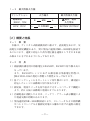
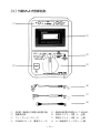
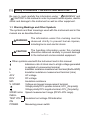
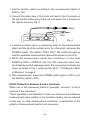
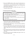
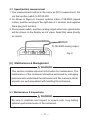
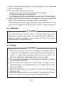
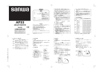
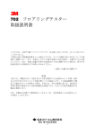
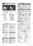
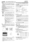
DIGITAL INSULATION METER
WITH VOLTAGE & SPEED RANGE
取扱説明書
INSTRUCTION MANUAL
ディジタル式絶縁抵抗計M53形
(電圧・速度測定機能付)
― 新JIS規格 測定電圧特性に準拠 ―
はじめに
このたびは三和ディジタル式絶縁抵抗計M53形をお買い上げいた
だき、誠にありがとうございます。
本製品のご使用にあたりましては、取扱説明書に記載されている
内容をよくお読みいただき、正しく安全にご使用ください。
取扱説明書を読まずに使用された際に万一、取り扱いミス等によ
り、けがや感電などの人身事故および、本器や他の機器の破損につ
ながるなど、トラブルが発生する原因になりますので、必ず本取扱
説明書をよくお読みいただいてからご使用くださいますようお願い
致します。
なお、
この取扱説明書は製品と一緒にして大切に保管してください。
目 次
頁
[1] 安全に関する項目∼ご使用前に必ずお読みください∼ …
1−1 警告マークなどの記号説明 …………………………
1−2 安全使用のための警告文 ……………………………
1−3 最大許容入力値 ………………………………………
1
1
2
3
[2]概要と特長 …………………………………………………… 3
2−1 概 要 ………………………………………………… 3
2−2 特 長 ………………………………………………… 3
[3]外観および各部名称 ………………………………………… 4
[4]測定方法 ……………………………………………………… 5
4−1 測定前の準備 ………………………………………… 5
4−2 内蔵電池の確認 ……………………………………… 5
4−3 内蔵電池の交換 ……………………………………… 6
4−4 絶縁抵抗の測定(MΩ) ……………………………… 7
4−5 交流電圧の測定(ACV) ……………………………… 9
4−6 直流電圧の測定(DCV)……………………………… 10
4−7 速度(m/min)の測定 ………………………………… 11
[5]保守管理について ………………………………………… 11
5−1 保守点検 ……………………………………………… 11
5−2 校 正 ………………………………………………… 12
5−3 保管について ………………………………………… 12
[6]アフターサービスについて ……………………………… 13
6−1 保証期間について …………………………………… 13
6−2 修理について ………………………………………… 13
6−3 お問い合わせ先 ……………………………………… 14
[7]仕 様 ……………………………………………………… 15
7−1 絶縁抵抗測定部 ……………………………………… 15
7−2 交流電圧測定部 ……………………………………… 15
7−3 直流電圧測定部 ……………………………………… 15
7−4 共通仕様 ……………………………………………… 16
7−5 付属品 ………………………………………………… 16
保証書、保証規定
[1] 安全に関する項目∼ご使用前に必ずお読みください∼
本文中の“
警告”および“
注意”の記載事項は、けがや感
電などの人身事故あるいは、本器や他の関連機器の破損防止のため
必ずお読みください。
1−1 警告マークなどの記号説明
本器および取扱説明書に使用されている記号と意味について
■以下の項目は、安全にご使用いただくため、特に重要な事項を示
します。
警告
やけどや感電など人身事故を防止するため、必ず
守っていただきたい項目です。
注意
本器や他の関連機器を壊すおそれがあるため、お
取り扱いについて注意していただきたい項目です。
■本器および取扱説明書に使用されている記号
測定端子に高電圧が発生あるいは、印加されることに
よる危険マーク
E
絶縁抵抗測定端子
(EARTH側)
L
〃 (LINE側)
ACV
交流電圧
DCV
直流電圧
MΩ 絶縁抵抗
V. SPEED
電圧および、速度測定端子
+
電圧極性 DCV :+プラス
(正極)
、ACV :∼(極性なし)
∼
、ACV :∼( 〃 )
−
〃
DCV :−マイナス(負極)
∼
SPEED m/min 速度測定レンジ(DCV 0∼20Vレンジ)
INSUL.
TEST VOLT 絶縁抵抗測定電圧印加表示
ON
POWER
測定用スイッチ
−1−
1−2 安全使用のための警告文
警 告
漓測定の際は、被測定物の種類(絶縁抵抗、交流電圧、直流電
圧)をよく確認して、それに適合するファンクションを選ん
でください。
滷規定されている最大許容入力値を超える電圧や信号を入力し
ないでください。
(最大許容入力値 次頁の 1−3 参照)
澆取扱説明書による電池交換の場合を除き、ケースまたは電池
蓋は開けないでください。
またそれ以外の修理や改造および分解はしないでください。
潺テストリード線は必ず指定のものを使用してください。
潸テストリード線は、絶縁被覆が損傷していたり芯線が露出し
ている場合は、交換するなどして使用者が自分で修理しない
でください。
澁測定中は他のファンクションに切り換えないでください。
澀本器または手が水などで濡れた状態および、湿度の高い場所
(85%RH以上)で使用しないでください。
潯測定中はテストリード線の金属部分には触れないでくださ
い。
潛所定の測定ができない不良品を使用しないでください。
濳大電力および最大許容入力値を超える高電圧回路では使用し
ないでください。
潭年一回の点検は必ず行ってください。
−2−
1−3 最大許容入力値
ファンクション
入力端子
絶縁抵抗
(500V、15V)
ACV、DCV
E
∼
MΩ
V. SPEED
最大許容入力値
電圧、電流
入力禁止
L
∼
AC750V、
DC750V
[2]概要と特長
2−1 概 要
本器は、ディジタル式絶縁抵抗計に加えて、直流電圧および、交
流電圧の測定機能があり、更に別売の速度計SE−9000形を接続す
ることにより、速度に対応した出力電圧値を速度としてそのまま読
み取ることもできるようになっております。
2−2 特 長
1)絶縁抵抗測定時の印加電圧がDC500V、DC15Vの切り換え式に
なっています。
また、DC500Vレンジにおける測定端子印加電圧特性は、
JIS C 1302−1994の規定に準拠した特性となっております。
2)各ファンクションともオートレンジ切り換えにより、測定値に
対応したレンジに自動的に切り変わります。
3)測定後、電源スイッチを切り忘れてもオートパワーオフ機能に
より、約1分後に自動的に電源がオフとなります。
4)内蔵電池が消耗したときは、バッテリ・アラーム表示機能によ
り電池交換の時期がわかります。
5)別売速度計SE−9000形接続により、エレベータなどの昇降機
やベルトコンベアなど被測定対象から離れた所での速度が測定
できます。
−3−
[3]外観および各部名称
盧
盪
眈
蘯
盻
眇
赤(+
∼)
眄
黒(−
∼)
眩
黒
盧 測定端子(絶縁抵抗、
交流電圧、
直流電圧共通)
蘯 ファンクションスイッチ
眈 絶縁抵抗測定電圧印加表示ランプ(赤色LED)
眇 赤色テストリード線(L、+
∼側)
眄 黒色テストリード線(E、−
∼側)
盻 POWERスイッチ(電源スイッチ)
眩 ピン接続用クリップ付リード線
盪 液晶表示部
−4−
[4]測定方法
4−1 測定前の準備
警 告
安全にご使用いただくため、本器を使用する前には必ず本器の
外観および、付属品の点検を入念に行ってください。
漓落下等による損傷がないかよく点検してください。
滷付属のテストリード線の絶縁被覆が損傷していたり、芯線が
露出している場合は感電の危険性があります。ご使用前に入
念に点検してください。
参考
電源スイッチの動作とオートパワーオフについて
本器の電源スイッチ(POWER)は、各ファンクションとも押す毎に
ON、OFFが切り換わるオルタネート式の動作となっております。
測定後、電源スイッチを切り忘れてもオートパワーオフ機能により、
約1分後に自動的に電源がOFFとなりますが、内蔵電池の消耗を防
ぐためにも、測定後はできるだけ電源スイッチをもう一度押して
OFFにするようにしてください。
4−2 内蔵電池の確認
1)測定端子には何も接続しない状態にしておきます。
2)ファンクション・スイッチを絶縁抵抗測定レンジの500Vまた
は15Vレンジに切り換えます。
3)測定用POWERスイッチを押します。
4)絶縁抵抗測定電圧印加表示赤色ランプ(INSUL. TEST VOLT
ON)が点灯し、第1図のように表示されれば内蔵電池は正常
です。
第1図
−5−
5)POWER ON により、INSUL. TEST VOLT ONランプが点灯せ
ず、表示部に何も表示されない場合は、電池が完全に消耗して
いるか、電池が入っていないことが考えられますので、リア
ケース裏面の電池蓋を取り外し、下記の4−3内蔵電池の交換
の項を参照の上、新しい電池を装着してください。
6)電池は入っているが、同様にINSUL. TEST VOLT ON ランプ
が点灯せず表示部に何も表示されない場合は、電池端子金具の
接触不良も考えられますので、リアケース裏面の電池蓋を取り
外し、電池と端子金具の接触を点検してください。
7)POWER ON により、INSUL. TEST VOLT ON ランプは点灯す
るが、表示部左下部に第2図のような「B」マークが表示され
た場合は、内蔵電池の消耗を意味しますので新しい電池と入れ
換えてください。
第2図
4−3 内蔵電池の交換
1)ファンクション・スイッチを中央のOFFにセットします。
警 告
電池の交換にあたっては、ファンクション・スイッチがOFFの
位置にあることを必ず確認してから行ってください。
2)電池交換は次頁の第3図を参照の上行ってください。
3)まず、リアケース裏面の電池蓋の止めネジを取り外し、上部中
A )の四角凸部分を指で押しながら下部へスライド
央(第3図⃝
B )の指示通り
させますと電池蓋がはずれますので、(第3図⃝
電池極性を間違えないよう正しく装着してください。
4)装着確認後、再び電池蓋を元の通りリアケースに挿入し、止め
ネジで固定します。
−6−
単3型 1.5V 電池(6個)
電池蓋
押しつつ
スライド
φ3mm
止めネジ
A
⃝
第3図
蘆電池蓋
B
⃝
蘆電池の極性配置
注 意
漓電池は必ず指定のもの(単三形アルカリ電池)を使用してく
ださい。
滷電池は性能劣化防止のため、全部同時に新品をご使用くださ
い。
4−4 絶縁抵抗の測定(MΩ)
警 告
漓絶縁抵抗測定レンジでPOWER ON(INSUL. TEST VOLT
ON表示ランプ点灯)の状態では、E−L端子間に500Vまたは
15Vが印加されており、危険ですので測定端子に接続された
テストリード線金属部分には触れないようにしてください。
滷測定のときは、被測定箇所に電圧が印加されていないことを
確認して作業を行ってください。
澆被測定物の内容、例えば容量性のものでは測定終了後、しば
らくの間被測定物に本器の印加電圧がチャージされている場
合がありますのでご注意ください。
−7−
1)ファンクション・スイッチを被測定対象に合わせて500Vまた
は15Vに切り換えます。
2)第4図のように黒色テストリード線の黒色プラグを左側のE端
子に、赤色テストリード線の橙色プラグを右側のL端子にそれ
ぞれ差し込み、黒色テスト棒の先端にピン接続用クリップリー
ド線を接続します。
黒
赤
第4図
3)被測定点の一方に黒色クリップを接続し、他の測定点に赤色テ
スト棒の先端を当てて、測定用POWERスイッチを押しますと、
絶縁抵抗測定電圧印加表示ランプ(INSUL. TEST VOLT ON)
が点灯し、表示部には求める抵抗値が指示されます。
4)被測定物が500Vで200MΩ以上、15Vで20MΩ以上のときは、測
定端子間オープンのときと同様、 5頁[4]4−2 内蔵電池の確
認の項における第1図のような入力オーバー表示状態となりま
す。
5)測定が終了しましたら、測定用POWERスイッチをもう一度押
してPOWER OFFにするか、ファンクション・スイッチをOFF
の位置に切り換えてください。
参考
E、L端子について
被測定点の一点が接地されているときは、接地側に本器のE端子測
定リード線を接続してください。
これは、この方が測定値が小さく指示されるのが一般的ですので使
用上の安全性を考慮してこのように約束されているからです。これ
以外の一般の測定では、この測定端子の極性はどちらでも差し支え
ありません。
−8−
参考
測定中「B」マークが表示された場合について
500Vレンジにて絶縁抵抗測定中、指示値が極端に小さいときバッ
テリ・アラームの「B」マークが表示されることがあります。
これは測定抵抗値が極端に小さいときは電源消費電流が大きく、電
池の消耗による容量不足より、内部動作電圧が規定電圧値以下に低
下し、この「B」マークが表示される状態となります。
このような場合は電池消耗の時期と判断し、新しい電池に交換して
ください。
4−5 交流電圧の測定(ACV)
警 告
漓ACVレンジの最大許容入力電圧は750Vまでであり、それを
超える電圧は絶対に入力しないでください。
滷AC25VRMS以上の電圧は人体に危険です。
測定にあたっては十分ご注意ください。
澆測定中はファンクション・スイッチを絶対に切り換えないで
ください。
潺絶対に濡れた手では測定しないでください。
1)ファンクション・スイッチをACVに切り換えます。
2)第5図のように黒色テストリード線の黒色プラグを左側の−
∼端
子に、赤色テストリード線の橙色プラグを+
∼端子にそれぞれ接
続します。
黒
赤
第5図
−9−
3)測定用POWERスイッチを押し、POWER ONの状態で赤、黒テ
ストリード線の先端を被測定点に接続すると、表示部に求める
電圧値が指示されます。
4)測定が終了しましたら、測定用POWERスイッチをもう一度押
してPOWER OFFにするか、ファンクション・スイッチをOFF
の位置に切り換えてください。
4−6 直流電圧の測定(DCV)
警 告
漓DCVレンジの最大許容入力電圧は750Vまでであり、それを
超える電圧は絶対に入力しないでください。
滷DC60V以上の電圧は人体に危険です。
測定にあたっては十分ご注意ください。
澆測定中はファンクション・スイッチを絶対に切り換えないで
ください。
潺絶対に濡れた手では測定しないでください。
1)被測定電圧のレベルに応じてファンクション・スイッチの設定
をしますが、未知の電圧値の場合は先ずDCVの0∼750V側に切
り換えます。
2)交流電圧(ACV)測定のときと同様、前頁の第5図のように赤、
黒テストリード線のプラグをそれぞれ測定端子に接続します。
3)測定用POWERスイッチを押し、POWER ONの状態で黒色テス
ト棒の先端をアースライン(低圧側)に、赤色テストリード棒
の先端を被測定点(高圧側)にあてると、表示部に求める電圧
値が指示されます。
4)指示値が20V以下の場合は、一度POWER OFFにしてからファ
ンクション・スイッチをDCVの0∼20V側に切り換えて、再度
測定します。
5)測定が終了しましたら、測定用POWERスイッチをもう一度押
してPOWER OFFにするか、ファンクション・スイッチをOFF
の位置に切り換えてください。
− 10 −
4−7 速度(m/min)の測定
1)測定方法は直流電圧(DCV)のときと同じですが、ファンク
ション・スイッチをDCVの0∼20Vに設定します。
2)第6図のように、別売品のSE−9000形速度計からのアナログ
+側赤色プラグを本器L端子の右側に、⃝
−側黒
出力用コードの⃝
色プラグをE端子にそれぞれ接続します。
3)測定用POWERスイッチを押しますと速度計からのアナログ出
力値が mVで表示されますので、この数値をそのままm/minと
して読み取ります。
SE−9000 アナログ出力へ
第6図
[5]保守管理について
警 告
この項目は保安上重要ですので、製品の内容および本取扱説明
書をよく理解して、製品の取扱に熟知した管理者が行ってくだ
さい。
5−1 保守点検
警 告
長期間安全にご使用いただき、また品質を維持するためにも必
ず保守点検を行ってください。
− 11 −
1)落下などにより、本器の外観が損傷していないか?
2)テストリードは
・入力端子にプラグを差し込んだとき緩みがないか?
・テストリードのコード部分が損傷していないか?
・テストリードのどこかの箇所から芯線が露出していないか?
3)ファンクション・スイッチつまみに上部から強い圧力をかけて
はいないか?(スイッチの接触不良の原因となる)
以上の項目に該当する場合はそのまま使用せず、修理または新
しいものと交換してください。
5−2 校 正
警 告
安全と確度の維持のため1年に1回以上は点検・校正を実施し
てください。
なお、点検・校正については販売代理店または発売元にお問い
合わせください。
5−3 保管について
注 意
漓パネル、リアケースなどは揮発性溶剤や熱に弱いため、シン
ナーやアルコールなどで拭いたり、高熱を発生するものの近
くには置かないようにしてください。
お手入れをする場合は、乾いた柔らかい布などで軽く拭き取
るようにしてください。
滷振動の多い場所や落下のおそれのある場所には保管しないで
ください。
澆直射日光下や極端な高温、低温そして多湿および、有毒ガス
が発生するような場所での保管は避けてください。
潺本器を使用しないときは、ファンクション・スイッチを必ず
OFFの位置にセットしておいてください。
潸長時間使用されない場合は、内蔵電池は必ず抜いて保管して
ください。
− 12 −
[6]アフターサービスについて
6−1 保証期間について
本製品の保証期間は、お買い上げの日より 3 年間です。
ただし、日本国内で購入し日本国内でご使用いただく場合に限ります。
また、製品本体の確度は1年保証、製品付属の電池、ヒューズ、テス
トリード等は保証対象外とさせていただきます。
6−2 修理について
1)修理依頼の前に次の項目をご確認ください。
・内蔵電池の容量はありますか?装着の極性は正しいですか?
・テストリードは断線していませんか?
・内蔵ヒューズは切れていませんか?
2)保証期間中の修理
・保証書の記載内容によって修理させていただきます。
3)保証期間経過後の修理
・修理費用や輸送費用が製品価格より高くなる場合もあります
ので、事前にお問い合わせください。
・本品の補修用性能部品の最低保有期間は、製造打切後 6 年間
です。この補修用性能部品保有期間を修理可能期間とさせて
いただきます。ただし購買部品の入手が製造会社の製造中止
等により不可能になった場合は、保有期間が短くなる場合も
ありますのでお含みおきください。
− 13 −
4)修理品の送り先
・製品の安全輸送のため、製品の 5 倍以上の容積の箱にテスト
リードも一緒に入れ、十分なクッションを詰め、箱の表面に
「修理品在中」と明記してお送りください。
・輸送にかかる往復の送料は、お客様のご負担とさせていただ
きます。
[送り先] 三和電気計器株式会社・羽村工場サービス課
〒205-8604 東京都羽村市神明台4-7-15
TEL(042)554-0113
6−3 お問い合わせ先
三和電気計器
(株)
東京本社
:TEL(03)
3253―4871
FAX(03)3251―7022
大阪営業所 :TEL(06)6631―7361
FAX(06)6644―3249
三和電気計器
(株)
ホームページ:http://www.sanwa-meter.co.jp
お客様計測相談室:
0120―51―3930
受付時間 9:30∼12:00 13:00∼17:00(土日祭日を除く)
− 14 −
[7]仕 様
7−1 絶縁抵抗測定部
1)測定電圧
DC500V、DC15V 2レンジ式
2)測定電圧・ DC500Vレンジ JIS C 1302(1994)
規格に準拠
測定端子開放 600V(+20%max.)
電流特性
500kΩにて>500Vを保証
測定端子短絡電流 1.6mA max.
DC15Vレンジ >1MΩにて15V±10%
3)測定範囲
DC500Vレンジ
0∼2MΩ/1MΩ∼20MΩ/10MΩ∼200MΩ
3オートレンジ切り換え式
DC15Vレンジ 0∼2MΩ/1MΩ∼20MΩ
2オートレンジ切り換え式
4)測定確度
±
(2%reading+2digit)以内
5φ赤色LED
5)印加電圧表示
7−2 交流電圧測定部
1)測定範囲 0∼750Vmax.
0∼200V/10V∼750V 2オートレンジ切り換え式
2)測定確度 ±(1%reading+0.5%Ranges+1digit)以内
周波数 50Hz∼400Hz
3)入力抵抗
10MΩ
7−3 直流電圧測定部
1)測定範囲
0∼20V、0∼750Vmax. 2レンジ式
0∼20Vレンジ
0∼2000mV/1V∼20V
2オートレンジ切り換え式
0∼750Vレンジ
0∼200V/10V∼750V
2オートレンジ切り換え式
※速度(m/min)
は0∼20Vレンジの下位レンジ
0∼2000mVレンジにて測定
1m/min=1mV 速度計SE-9000取扱説明書参照
2)測定確度 ±(0.5%reading+0.5%Ranges+1digit)以内
3)入力抵抗
10MΩ
− 15 −
7−4 共通仕様
1)ADコンバータ
2)表示部 3)入力オーバー表示
4)極性表示
5)測定端子
動作方式 二重積分形
サンプリングレート 約2.5回/秒 最大1999 3 1/2 桁 LCD表示
最大桁「1」のみ表示
DCV測定時「−」のみ自動表示
絶縁抵抗 MΩ:E、L 電圧 ACV&DCV (V.SPEED):+
∼、−
∼
6)使用温湿度範囲
0℃∼40℃ 85%RH以下(結露のないこと)
7)確度保証
温湿度範囲
15℃∼30℃ 80%RH以下
(結露のないこと)
8)内蔵電池 単三形アルカリ電池(LR6形)6ケ(9V)
9)内蔵電池寿命(電池電圧7V低下時間)
パワーオン/オフ各々1分の連続繰り返しにて
絶縁抵抗測定
(測定端子開放) 約 50時間
電圧測定
約300時間
10)バッテリ・アラーム
電池電圧 約 7 V以下にてLCD「B」マーク表示
11)オートパワーオフ時間
パワーオン後、約1分でオートパワーオフ
12)寸法・重量 175×115×55mm 約600g
7−5 付属品
1)橙色プラグ付赤色テストリード線(L、+
∼端子)
2)黒色プラグ付黒色テストリード線(E、−
∼端子)
3)ピン接続用クリップ付リード線 以上3本セット:TL−M54
4)取扱説明書 5)携帯ケース:C−M53(コードケース込み)
1本
1本
1本
1部
1個
説明中の仕様は性能向上のため、お断わりなく変更することが
ありますのでご了承ください。
− 16 −
保証書
ご氏名
型 名
様
ご住所
この製品は厳密なる品質管理を経てお
届けするものです。
本保証書は所定項目をご記入の上保管
していただき、アフターサービスの際
ご提出ください。
※下記の保証規定をよくお読みください。
※本保証書は再発行はいたしませんの
で大切に保管してください。
〒
TEL
保証期間
ご購入日 年 M53
製造No.
月より 3 年間
本社=東京都千代田区外神田2−4−4・電波ビル
郵便番号=101-0021・電話=東京(03)3253−4871豎
保証規定
保証期間中に正常な使用状態のもとで、万一故障が発生した場合には無償で修理いたします。
ただし下記事項に該当する場合は無償修理の対象から除外いたします。
記
1. 取扱説明書と異なる不適当な取扱いまたは使用による故障
2. 当社サービスマン以外による不当な修理や改造に起因する故障
3. 火災水害などの天災を始め故障の原因が本計器以外の事由による故障
4. 電池の消耗による不動作
5. お買上げ後の輸送、移動、落下などによる故障および損傷
6. 本保証書は日本国内において有効です。
This warranty is valid only within Japan.
年 月 日
修理内容をご記入ください。
※無償の認定は当社において行わせていただきます。
DIGITAL INSULATION METER
WITH VOLTAGE & SPEED RANGE
INSTRUCTION MANUAL
[1] Safety Precautions --- Be sure to read before use. --Be sure to read carefully the information under “
WARNING” and
“ CAUTION” in this manual in order to prevent human injuries, electric
shock and damage to the instrument as well as other equipment.
1-1 Warning Markings and Other Symbols
The symbols and their meanings used with the instrument and in this
manual are as described below.
WARNING
CAUTION
The information under this marking must be
observed strictly to prevent human injuries,
including burns and electric shock.
The handling information under this marking
should be observed carefully to prevent damage
to the instrument and associated equipment.
Other symbols used with the instrument and in this manual
Indicates a risk of shock due to a high voltage generated
or applied at a measuring terminal.
E
Insulation resistance measurement terminal (Earth=GND)
L
Insulation resistance measurement terminal (Line)
ACV
AC voltage
DCV
DC voltage
MΩ
Insulation resistance
V. SPEED
Voltage and speed measurement terminal
Voltage polarity DCV:+positive terminal, ACV:~(No polarity)
Voltage polarity DCV:-negative terminal, ACV:~(No polarity)
SPEED m/min Speed measurement range (DCV0~20V range)
INSUL.
TEST VOLT Insulation test voltage ON indication
ON
POWER
Measuring power switch
−1−
1-2 Warning Messages for Safety
WARNING
1. Check the measurement type (insulation resistance, DC or AC
voltage) before measurement and select the appropriate
function for it.
2. Do not apply a voltage or signal exceeding the specified
maximum allowable input. (For the maximum allowable input
voltage value, see section 1-3 on the next page.)
3. Do not open the case or battery cover unless replacing the
batteries as described in this manual.
4. Always use the test leads specified in the manual.
5. If the insulation coating of a test lead is damaged or its
conductor wire is exposed, do not attempt to repair it.
Instead, replace with a new test lead.
6. Do not switch the measuring function during measurement.
7. Do not use the instrument when it is moistened, when your
hand is wet or when the ambient humidity is high (85%RH or
more).
8. Do not touch the metallic parts of the test leads during
measurement.
9. Do not use the instrument if it is defective and incapable of
making the specified measurements.
10.Do not use the instrument using high-power or higher voltage
circuitry than the maximum allowable input.
11.Be sure to conduct annual inspections.
−2−
1-3 Maximum Allowance Input Value
Function
Input terminal
Insulation resistance
(500V, 15V)
ACV, DCV
E
∼
MΩ
V. SPEED
Max allowance input value
Voltage or Current
Input prohibited
L
∼
AC750V, DC750V
[2] Overview and Features
2-1 Overview
This device is a digital insulation resistance tester, with DCV & ACV
measurement functions.
In addition to that, it also has optional speed measurement function
(Sanwa speed meter SE-9000 is necessary to use this function), that
enables to read output voltage value directly as a speed value.
2-2 Features
1. Two test voltage ranges DC500V and DC15C
2. Auto range
3. Auto power off after one minute from power-on.
4. Low battery indication function.
5. With optional tachometer SE-9000, remote speed measurement
can be made.
−3−
[3] Appearance and Appellation
(1)
(2)
(5)
(3)
(4)
(6)
(
)
(
)
(7)
(8)
(1) Measurement terminal (Insulation
resistance, ACV, DCV)
(2) LCD
(3) Function switch
(4) Power switch
(5) Insulation resistance measurement
voltage input indication lamp (red LED)
(6) Red test lead (L, side)
(7) Black test lead (E, side)
(8) Clip lead for connecting pin
−4−
[4] Measuring Methods
4-1 Preparations
WARNING
For safe use of the instrument, check its appcarance and associated
accessories carefully before use.
1. Check for damage due to dropping, etc.
2. There is a risk of electric shock if the insulation coating of a test
lead or its conductor wire is exposed. Check the test leads
carefully before use.
NOTE: Operation of the POWER Switch and Auto Power OFF
The POWER switch of the instrument toggles, or alternates operation,
so that each successive press switches the selected measuring function
from ON to OFF, and vice versa. The auto power OFF feature provided
turns power OFF automatically in about 1 minute, as a safeguard for
when you forget to set the POWER switch to OFF after use. Still, we
recommend pressing the POWER swith to OFF after measurement to
save the power of the built-in batteries.
4-2 Checking the Built-in Batteries
1. Do not connect any leads to the measuring terminals.
2. Set the function switch to 500V or 15V.
3. Press the POWER switch.
4. The built-in batteries are normal if the INSUL. TEST VOLT ON
indicator (red LED) lights up and the LCD looks as shown in Fig. 1.
Fig 1
−5−
5. If the INSUL. TEST VOLT ON indicator does not light and the
LCD shows nothing even when the POWER switch is pressed to
ON, the batteries may be exhausted completely, or no battery has
been loaded. In this case, remove the battery cover on the rear
case and insert new batteries as described in section 4-3,
“Replacing the Built-in Batteries” on the next page.
6. If the INSUL. TEST VOLT ON indicator does not light and the LCD
shows nothing, although unexhausted batteries are loaded, it is
possible that the battery terminal contacts have failed. In this case,
remove the battery cover on the rear case and check the contacts
between the batteries and terminals.
7. If the INSUL. TEST VOLT ON indicator lights up but the LCD shows
the “B” marking as shown in Fig. 2 when the POWER switch is
pressed to ON, the built-in batteries are nearly exhausted. In this
case, replace them with new batteries.
Fig 2
4-3 Replacing the Built-in Batteries
1. Set the function switch to OFF on the center position.
WARNING
Make sure that the function switch is set to OFF before proceeding
to the battery replacement operation.
2. Refer to Fig. 3 below for the battery replacement.
3. Remove the lock screw on the battery cover on the rear case, then
remove the battery cover by sllding it down while pushing the
square projection on the top center (Fig. 3[A]) with your finger, and
insert batteries in correct polarity positions as shown by Fig. 3[B].
4. After checking that the batteries have been inserted correctly,
place the battery cover in the original position on the rear case and
fasten with the lock screw.
−6−
1.5V battery
Battery cover
Press and
slide
φ3mm
screw
A
⃝
Fig. 3
B
⃝
CAUTION
1. Always use the specified batteries (LR6 batteries).
2. To prevent performance degradation, replace all six batteries
with six brand-new ones when the time comes to replace
batteries.
4-4 Measurement of insulation resistance (MΩ)
WARNING
1. When the power is ON with the insulation resistance measuring
function selected (when the INSUL. TEST VOLT ON indicator
is lit), a high voltage for insulation resistance measurement is
applied across the E-L terminals. To avoid the risk of electric
shock, do not touch the metallic parts of the test leads connected
to the measuring terminals.
2. Make sure that the object to be measured is not subjected to
voltage before proceeding to measurement.
3. Certain measurement objects (capacitive objects, for example)
may retain the voltage applied from this instrument for some
time after the completion of the measurement.
−7−
1. Set the function switch according to the measurement object, to
500V or 15V.
2. Connect the black plug of the black test lead to the E terminal on
the left and the amber plug of the red test lead to the L terminal on
the right as shown in Fig. 4.
Black
Red
Fig. 4
3. Connect the black clip to a measuring point on the measurement
object and the tip of the red test rod to the other point, and press the
POWER switch. The INSUL. TEST VOLT ON switch will light up
and the resistance measurement value will be shown on the LCD.
4. When the measurement object has resistance of more than
200MΩ at 500V or 20MΩ at 15V, the LCD shows the same overinput display as that displayed when the measuring terminals are
open, as shown in Fig. 1 under section [4]4-2, “Checking the Builtin Batteries” on page 5.
5. After measurement, press the POWER switch again to OFF or set
the function switch to OFF.
NOTE: Distiaction Between E and L Terminals
When one of the measuring points is grounded, connect it to the E
terminal of the instrument.
This is specified in consideration of safe use, because the resistance
measurement value reading in the insulation testing can be reduced
in this way. In other measurement operations, consideration of the
polarity of measurement points is not necessary.
−8−
NOTE: In Case the “B” Marking is Displayed During Measurement
When the resistance measurement value in an insulation test is
extremely small, the LCD sometimes shows the “B” marking which is
usually used as the battery alarm indicator. In the present case, the
“B” marking is displayed because an extremely small resistance
measurement value means consurption of large battery current and
the drop in capacity due to exhaustion of the batteries causes the
internal operating voltage to fall below the specified level.
4-5 Measuring the AC Voltage (ACV)
WARNING
1. The maximum allowable input voltage of the ACV range is
750 V. Never apply a higher voltage than this.
2. Voltages higher than 25 Vrms AC are hazardous to the human
body. Be very careful during measurement.
3. Never attempt to change the function switch position during
measurement.
4. Never touch the device with a wet hand.
1. Set the function switch to ACV.
2. Connect the amber plug of the red test lead to the terminal on
the right and the black plug of the black test lead to the terminal
on the left as shown in Fig. 5.
Black
Red
Fig. 5
−9−
3. Press the POWER switch to ON, connect the black clip to a
measuring point on the measurement object, and apply the tip of
the red test rod to another measuring point. The LCD will show the
measurement voltage value.
4. After measurement, press the POWER switch again to OFF or set
the function switch to OFF.
4-6 Measuring the DC Voltage (DCV)
WARNING
1. The maximum allowable input voltage of the DCV range is
750V. Never apply a higher voltage than this.
2. DC Voltages higher than 60V are hazardous to the human body.
Be very careful during measurement.
3. Never attempt to change the function switch position during
measurement.
4. Never touch the device with a wet hand.
1. Set the function switch to appropriate range, but if the voltage to be
measured is uncertain, set it to DCV0-750V range.
2. Same as the ACV measurement, connect both black & red plugs to
measurement terminals.
3. Press the POWER switch to ON, connect the black clip to the earth
line (lower voltage side) and red point on the measurement object
(higher voltage side), the LCD will show the measurement voltage
value.
4. If the measured value is less than 20V, then turn off the device, and
make measurement again by setting the function switch to DCV020V range.
5. After measurement, press the POWER switch again to OFF or set
the function switch to OFF.
− 10 −
4-7 Speed(m/min) measurement
1. The measurement method is the same as DCV measurement, but
set the function switch to DCV0-20V.
2. As shown in Figure 6, connect optional cable of SE-9000 (speed
meter), positive red plug to the right side of L terminal, and negative
black plug to E terminal.
3. Press power switch, and then analog output value from speed meter
will be shown on the display as mV value. Read that value directly
as m/min.
To SE-9000 analog output
Fig. 6
[5] Maintenance & Management
WARNING
This section contains important information for maintenance. The
maintenance of the instrument should be performed by managing
personnel who understand the instrument and this manual in detail,
and who are well-acquainted with handling the instrument.
5-1 Maintenance & Inspections
WARNING
Be sure to maintain and inspect to ensure safe, long-lasting
optimum-performance use of the instrument.
− 11 −
1. Check that the external finish of the instrument is not damaged
due to dropping etc.
2. Check the test leads to ensure that
· a plug is not loose when it is inserted into a terminal;
· the test lead coating is not damaged;
· the conductor wires are not exposed from any part of the test leads.
3. Check that the function switch is not subject to strong pressure from
above. (This could lead to a contact failure of the switch.)
If the instrument cannot comply with any of the above checks, do not
use it as it is. Service the defective part or replace it with a new part.
5-2 Calibration
WARNING
To maintain safety and accuracy, conduct inspections and
calibration at least every year. For inspection and calibration,
please consult a dealer in your area or the local sales
representative for the instrument.
5-3 Storage
WARNING
1. The panel and rear case are not resistant to volatile solvents
or heat. Do not attempt to clean them with lacquer thinner or
alcohol, or place the instrument near a source of heat. To
clean the instrument, wipe lightly with a soft, dry cloth.
2. Do not store the instrument in a place subject to vibration, or where
the instrument may drop.
3. Do not store the instrument under direct sunlight, under
extremely high or low temperatures, or in a place where toxic
gas is generated.
4. When the instrument is not used, be sure to set the function
switch to OFF.
5. When the instrument is not to be used for a long period of time,
be sure to remove the built-in batteries before storing it.
− 12 −
[6] After-Sales Service
6-1 Warranty and Provision
Sanwa offers comprehensive warranty services to its end-users
and to its product resellers. Under Sanwa's general warranty
policy, each instrument is warranted to be free from defects in
workmanship or material under normal use for the period of one
(1) year from the date of purchase.
This warranty policy is valid within the country of purchase only,
and applied only to the product purchased from Sanwa authorized
agent or distributor.
Sanwa reserves the right to inspect all warranty claims to determine
the extent to which the warranty policy shall apply. This warranty
shall not apply to fuses, disposables batteries, or any product or
parts, which have been subject to one of the following causes:
1. A failure due to improper handling or use that deviates from the
instruction manual.
2. A failure due to inadequate repair or modification by people
other than Sanwa service personnel.
3. A failure due to causes not attributable to this product such as
fire, flood and other natural disaster.
4. Non-operation due to a discharged battery.
5. A failure or damage due to transportation, relocation or dropping
after the purchase.
6-2 Repair
Customers are asked to provide the following information when
requesting services;
1. Customer name, address, and contact information
2. Description of problem
3. Description of product configuration
4. Model Number
5. Product Serial Number
6. Proof of Date-of-Purchase
7. Where you purchased the product
− 13 −
Please contact Sanwa authorized agent / distributor / service
provider, listed in our website, in your country with above
information. An instrument sent to Sanwa / agent / distributor
without those information will be returned to the customer.
Note:
1. Prior to requesting repair, please check the following:
Capacity of the built-in battery, polarity of installation and
discontinuity of the test leads.
2. Repair during the warranty period:
The failed meter will be repaired in accordance with the
conditions stipulated in 6-1 Warranty and Provision.
3. Repair after the warranty period has expired:
In some cases, repair and transportation cost may become
higher than the price of the product. Please contact Sanwa
authorized agent / service provider in advance.
The minimum retention period of service functional parts is 6
years after the discontinuation of manufacture. This retention
period is the repair warranty period. Please note, however, if
such functional parts become unavailable for reasons of
discontinuation of manufacture, etc., the retention period may
become shorter accordingly.
4. Precautions when sending the product to be repaired
To ensure the safety of the product during transportation,
place the product in a box that is larger than the product 5
times or more in volume and fill cushion materials fully and
then clearly mark “Repair Product Enclosed” on the box
surface. The cost of sending and returning the product shall
be borne by the customer.
6-3 SANWA web site
http://www.sanwa-meter.co.jp
E-mail: [email protected]
− 14 −
[7] Specifications
7-1 Insulation Resistance Measuring Block
1. Rated voltage DC500V, DC15V, 2 ranges
2. Measuring voltage/current characteristics DC500V range
When measuring terminals are open 600V (+20% max.)
When measuring terminals are shorted Approx. 1.6 mA max.
DC15V range : 15V±10% at 1MΩ
3. Measurement range
DC500V range: 0 to 2MΩ/1M to 20MΩ/10M to 200MΩ, 3 auto
range switching
DC15V range : 0 to 2MΩ/1M to 20MΩ, 2 auto range switching
4. Measuring accuracy : Within ±(2% reading + 2 digit)
5. Applied voltage indication : Red LED with 5 mm dia.
7-2 AC Voltage Measuring Block
1. Measuring range
0 to 750 V max.
0 to 200V/10 to 750V, 2 auto range switching
2. Measuring accuracy :
Within ± (1% of reading + 0.5% of range + 1 digit)
Frequency : 50 to 400 Hz
3. Input resistance 10MΩ
7-3 DC Voltage Measuring Block
1. Measuring range : 0 to 20V, 0 to 750 V max, 2 range.
0 to 20V
0 to 2000mV/1V to 20V, 2 auto range switching
0 to 750V 0 to 200V/10V to 750V, 2 auto range switching
*Speed measurement (m/min) : 0 to 2000mV range
1m/min = 1mV (Refer to the instruction manual for SE-9000)
2. Measuring accuracy :
Within ± (0.5% of reading + 0.5% of range + 1 digit)
3. Input resistance 10MΩ
− 15 −
7-4 Common specifications
1. A/D converter
Operating system: Double integration
Sampling rate: Approx. 2.5 samplings/sec.
2. Display
LCD, max. 1999
3. Over-input indication Only the highest digit shows “1”.
4. Polarity indication
“—” when measuring DCV
5. Measuring terminals
Insulation resistance MΩ: E, L.
Voltage: ACV & DCV (V. SPEED) : ,
6. Operating temperature/humidity
0 to 40˚C, 85%RH (without condensation)
7. Accuracy guaranteed temperature/humidity
15 to 30˚C, 80%RH (without condensation)
8. Built-in batteries
LR06(IEC)(x6)
9. Built-in battery life (time until battery voltage drops to 7V)
When power is switched between ON and
OFF every minute in succession
Insulation resistance measurement (measuring
terminals open): Approx. 50 hours
AC voltage measurement: Approx. 300 hours
10. Battery alarm
LCD shows “B” mark when battery voltage
drops below 7V
11. Auto power OFF time Approx. 1 minute after power ON
12. Dimensions & weight
175 x 115 x 55 mm, approx. 600 grams
7-5 Accessories
1. Red test lead with amber plug (L, terminal) x 1
2. Black test lead with black plug (B, terminal) x 1
3. Alligator clip adapter x 1
Set of the avobe 3 test leads: TL-M54
4. Instruction manual x 1
5. Carrying case C-M53 (with cord case) x 1
The specifications in this manual may be subject to change for
performance improvement without notice.
− 16 −
MEMO
MEMO
本社=東京都千代田区外神田2−4−4・電波ビル
郵便番号=101-0021・電話=東京(03)3253−4871㈹
大阪営業所=大阪市浪速区恵美須西2−7−2
郵便番号=556-0003・電話=大阪(06)6631−7361㈹
SANWA ELECTRIC INSTRUMENT CO.,LTD.
Dempa Bldg., 4-4 Sotokanda2-Chome Chiyoda-Ku,Tokyo,Japan
植物油インキを使用しています。
03-0910 2040 2040