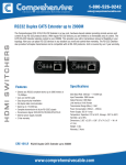
1
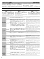
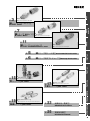
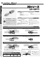
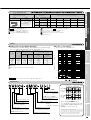
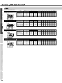
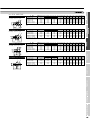
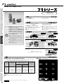
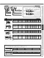
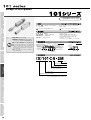
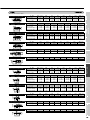
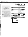
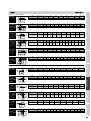
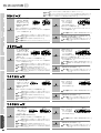
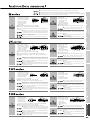
安全上のご注意
この「安全上のご注意」は、弊社製品を正しくお使いいただくための注意事項で、人体へ
の危害や財産などへの損害を未然に防止するためのものです。これらの注意事項は、取
扱いを誤った場合に発生する危害や損害の大きさの程度により、
「危険」
「警告」
「注意」
の3段階に区分しています。いずれの段階にも安全に関する重要な内容ですので、
(※2)、
ISO4413-1979(※3)、及
ISO4414-1982(※1)、及びJISB8370(1988)
(※4)と併せて必ず守ってください。
びJISB8361(1982)
(※1) ISO 4414-1982
(※2) JIS B 8370(1988)
Pneumatic fluid power…Recomendations for the application (※3) ISO 4413-1979
of equipment to transmission and control systems.
空気圧システム通則
(※4) JIS B 8361(1982)
危険
警告
Danger
very cases, mishandling of products could
a possible loss of life or serious injury.
falling within this category would likely be a
a high degree or urgency.
危険
Danger
Before selecting
注意
①水・グリコール系作動油をご使用の場合、メッキの種類によっては使用でき
ません。詳しくは弊社までお問い合わせください。
②カプラとニップルの組み合わせにおいて、他社製品との互換性はありません。
③弊社以外が組立、または再組立を行ったQ.D.C.製品については、保証でき
ない場合があります。
①When using the product for water-glycol based hydraulic fluids,
the product may not be able to be used depending upon the
types of plating. Please contact us if you need more information.
②Our products are not interchangeable with those of other
manufacturers for the coupler and nipple combination.
③In some cases, we may not be able to warranty Q.D.C. products
are assembled or reassembled by other companies.
警告
①Q.D.C.製品の取付方法に関する説明を掲載しています。必ず参照し、記載
されている注意事項に従って取り付けてください。
②ねじ部やシール面が破損したQ.D.C.製品のご使用は避けてください。
③弊社及び弊社認定工場以外が二次加工をしたり、本体を分解・改造した製品
は使用しないでください。
①Procedures are outlined in catalogues. Please read carefully and
follow the instruction.
②Avoid using of Q.D.C. if the screw part or the seal surface is
damaged.
③Please do not use products that have been dismantled/mantled
except by Nitta moore factory or authorized distributors.
注意
①Q.D.C.製品は放り投げたり、落としたりしないようにしてください。ねじ部や
シール面が傷つく恐れがあり、油漏れに至ることがあります。
②ねじ部は弊社規定の締め付けトルクでねじ込んでください。取付け側の材
質によっては膨らみや割れなどが生じることがありますので、取付け時は必
ず取付け側の強度をご確認ください。
①Avoid throwing or dropping Q.D.C., this may damage the threads
or seals, which could lead to fluid leaking.
②Tighten screws with the specified torque. Inspect the strength of
the material to which the item is affixed by inspecting for
expansion and cracks that can occur depending upon the
material strength.
警告
①加圧時にQ.D.C.製品に触れないでください。加圧中に不用意に近づいたり
触れたりすると、突然破損した場合、流体などが飛散して危険です。
②流体が高温の場合はQ.D.C.製品に触れないでください。
「やけど」の恐れ
があります。
①Do not touch or stand near Q.D.C. during pressurization. It is
possible for the product to become damaged at any time, which
could cause dangerous fluids to squirt out.
②Do not touch Q.D.C., the fluid inside may be very hot and you
could get burned.
①残圧を抜くときに、先端をハンマーなどで叩くことは避けてください。
②Q.D.C.製品をロータリージョイントやスィーベルジョイントの代替として、回
転させる使用方法は避けてください。
③金属粉や砂塵の多い場所では作動不良などの不具合が発生し故障の原因
となりますので、そのような場所での使用は避けてください。
④Oリングの摩耗や劣化、ニップルのシール部の傷、打痕などが生じた場合は
新品と交換してください。
⑤残圧を抜かずに接続、分離すると、破損や事故の恐れがあります。
⑥カプラとニップルを分離し長期間使用しない場合は、塵・埃の付着・侵入を防
止するため、ダストキャップを取り付けてください。
①Avoid hitting the edge with a hammer or other instrument when
trying to relieve residual pressure.
②Avoid rotating Q.D.C. and do not use it as a rotary or swivel joint.
③Avoid usingthe product in areas with either a high concentration
of sand or metal dust. This could lead to poor product
performance and subsequent breakdown.
④If the O-ring shows signs of wear of deterioration and there is a
scratch or dent on the seal area of the nipple, replace the
damaged parts with new ones.
⑤There is a possibility of domaging thee part by connecting or
disconnecting it without removing the residual pressure.
⑥If the coupler and nipple are separated and will not be used for an
extended period, protect the pieces with a dust cap to prevent
dust from contaminating the product.
Selection
Caution
Warning
取付時に!
Installation
Caution
Warning
4
使用時に!
注意
Caution
Storage
①Do not use with equipments and appliances designed for
sustaining human.
②Do not use with equipments and appliances requiring high-level of
safety.
①人体や、生命の維持・管理を目的とする機器・装置には使用できません。
②特に安全であることが必要な機器・装置には使用できません。
警告
選定時に!
5
Cases in this category where mishandling occurs, could
result in minor injuries or property damage only.
①Strictly follow proper usage instructions in catalogues.
②Do not use in applications with corrosive gas and/or inflammable
gas.
③Do not use in applications with extreme vibration and/or shock.
④Whenever using chemicals to transfer chemicals, check the
chemical Safety Data Sheets if released into the air.
Warning
保管時に!
The risk of injury is less than those falling within the
“danger” category, but also could result in serious
injury or loss of life in extreme cases.
①使用条件が、記載の「使用条件」を十分に満足することを確認してください。
②腐食性ガス・引火性ガス等が使用流体または雰囲気での使用はできません。
③過度の震動および衝撃の加わる場所では使用できません。
④薬品を流体および雰囲気で使用される場合は、必ず「耐薬品性一覧表」をご
確認ください。
警告
2
Use
取扱いを誤った場合に、軽傷を負うか、または物理的損害の
みが発生する危険な状態が生じることが想定される場合。
①With respect to handling Nitta Moore Products, the personnel
who design equipment's, apparatus or system to be installed, or
decision makers of specification should make all judgement of
the usage of the products. Those designers or decision-maker
should make, if necessary, adequate testing and analysis to
judge the suitability and take all responsibility for the safety
quarantee.
②The personnel who handle the products should have enough
knowledge and experience in this field.
③It can not be used for the equipment / apparatus of either
maintaining / Controlling the lives or being required extreme
safety.
④Please consult with us the applications are for the equipment's
related to the transportation of the mankind or for the vehicles or
for what will cause serious damage un case of failures, or for
what will affect human health such as the equipment's for
medical. Direct contact of drinking water and beverage.
Warning
3
Caution
取扱いを誤った場合に、死亡または重傷を負う危険な状態が
生じることが想定される場合。
①弊社製品の取り扱いに関しては、取付ける装置や機器・システムなどの
設計者または仕様を決定する人が判断してください。また、それらの設
計者または仕様を判断する人が、必要に応じてテストや分析などを行い
決定してください。これらの装置や機器・システムの所定の性能・安全
性の保証は、その適合性を決定した人の責任となります。
②弊社製品の取り扱いに関しては、十分な知識と経験を持った人が取り扱
うようにしてください。
③安全を確認できるまで装置や機器・システムなど弊社製品の取付けや取
り外しを絶対に行わないでください。
④人間の輸送を目的とする装置・機器・各種車両・航空などの乗り物や、
人間が乗ることを目的とするレジャー機器・装置への使用、仕様を誤っ
た際に人体へ直接影響が及ぶ医療装置や食品・飲料水に触れる機器への
使用については、弊社までお問い合わせください。
1
選定する前に!
Hydraulic fluid power…Generalrules for the application of
equipment to transmission and control systems.
油圧システム通則
注意
Warning
取扱いを誤った場合に、死亡または重傷を負う危険な状態が
生じることが想定され、かつ、危険発生時の警告の緊急性が
高い限定的な場合。
In these
result in
Incidents
cause for
The safety warnings are provided here to ensure proper and correct use of
our products in order to prevent injuries to the user and equipment damage.
The warnings are classified into the following three categories:
● Danger ● Warning ● Caution
The information here is extremely important and should be read closely along
(※2),
with the instructions in ISO 4414-1982(※1), JIS B 8370(1988)
ISO 4413-1979(※3), and JIS B 8361(1982)
(※4).
注意
Caution
①製品を保管される場合は、必ずゴミ等が付着しない場所に保管してください。 ①Please keep products in clean/dry place such as not to get
contaminated by dusts and other debris which may cause
ゴミ等が製品の内部に付着すると周辺機器に入り込み、故障の原因となる
problems with the connected equipments.
可能性があります。
②Please do not expose to direct sunlights and keep in a dry space
②直射日光を避け、40℃以下の温度で乾燥した所に保管してください。
under 40℃(104°
F).
③Q.D.C.製品の長期保管後のご使用は避けてください。製造後1年を目安に ③Avoid using Q.D.C. after being stored for a long time.
してください。
尚、本カタログの仕様は改良等により予告なしに変更することがあります。
All contents of this sample board are subject to change without notice.
3
●油圧・液体用
●For
P.
the oil pressure and liquid
Hシリーズ スチールタイプ
H series Steel
7
P.
Hシリーズ 真鍮タイプ
H series Brass
P.
●油圧・液体用
●For
the oil pressure and liquid
11
Hシリーズ SUS304タイプ
●油圧・液体用
H series SUS304 Stainless steel
5
P.6
P.
15
P.
●For
Hシリーズ用シール材
the oil pressure and liquid
Seal material for H series
Hシリーズ用ダストキャップ
●油圧(超高圧)用
●For
71シリーズ
the super-high pressure
71 series
17
P.
●空圧用ミニタイプ
●Mini-type
101シリーズ
19
P.
Dustcap for H series
for the air pressure
101 series
●空圧・液体用マイクロタイプ
●Micro-type
103シリーズ
for the air pressure and liquid
103 series
23
P.
耐薬品性一覧表
Chemical resistance
25
P.
取扱説明書
Instruction manual
材質
本 体:炭素鋼
シール:NBR(記号なし)
EPDM
BODY:Carbon steel
SEAL:NBR(no sign)
EPDM
(Order production/Put "E" at the end of each part number.)
(受注生産品/品番の最後に「E」をつけてください)
Fluorine rubber
ふっ素ゴム
(Order production/Put "V" at the end of each part number.)
(受注生産品/品番の最後に「V」をつけてください)
使用条件
特長
●流体の通過面積が広く、大流量を流す
ことが可能。
●PHタイプは残圧力下での接続が簡
単にできる「PHバルブ」内蔵。
●The possibility of large spills exist do
the high volume that can pass through
the system.
●The PH type has a built-in “PH valve”
that can be easily connected to relieve
residual pressure.
使 用 流 体:鉱物性一般作動油、
水、薬品類
使用温度範囲:
シール材質/NBR −30℃∼+93℃
EPDM −54℃∼+149℃
ふっ素ゴム −30℃∼+190℃
FLUID:General hydraulic oil, Water, Chemicals
WORKING TEMPERATURE:
Seal material
NBR −30℃∼+93℃(−22°
F∼+200°
F)
EPDM −54℃∼+149℃(−66°
F∼+300°
F)
Fluorine rubber −30℃∼+190℃(−22°
F∼+374°
F)
Attention:Thoroughly check the suitability
of the body material and the seal in whenever
used in conjunction with chemicals.
Attention:Avoid connecting VH type and
OH type under.
警告:薬品類で使用の場合は、本体材質、シール材
質との適性を十分に確認してください。
警告:VHタイプ、OHタイプは残圧下での接続はで
きません。
断面構造図
VHタイプ(バルブ付)
VHC バルブ付カプラ
VH type(With the valve)
VHN バルブ付ニップル
Coupler with the valve
バルブOリング/ Valve O-ring
スリーブスプリング/ Sleeve spring
ボディOリング/ Body O-ring
カプラボディ/ Coupler body
アダプタOリング/ Adapter O-ring
バルブOリング/ Valve O-ring
スリーブ/ Sleeve
アダプタ/ Adapter
バルブ/ Valve
スナップリング/ Snapshot ring
アダプタ/ Adapter
Nipple with the valve
ニップルボディ/ Nipple body
ボール/ Ball
アダプタOリング/ Adapter O-ring
バックアップリング/ Back up ring
バルブストップ/ Valve stop
バルブストップ/ Valve stop
バルブ/ Valve
バルブスプリング/ Valve spring
バルブスプリング/ Valve spring
開閉式バルブ機構を備えたタイプです。 It is a type having open-shut valve mechanism.
OHタイプ(バルブ無)
OHC バルブ無カプラ
OH type(Without the valve)
OHN バルブ無ニップル
Coupler without the valve
Nipple without the valve
スリーブスプリング/ Sleeve spring
ニップルボディ/ Nipple body
スリーブ/ Sleeve
スナップリング/ Snapshot ring
ボール/ Ball
カプラボディ/ Coupler body
バックアップリング/ Back up ring
ボディOリング/ Body O-ring
開放式のオープンタイプです。 It is an open type.
PHタイプ(PHバルブ付)
PHC PHバルブ付カプラ
PH type(With the PH valve)
PHN PHバルブ付ニップル
Coupler with the PH valve
バルブOリング/ Valve O-ring
スリーブスプリング/ Sleeve spring
カプラボディ/ Coupler body
ボディOリング/ Body O-ring
アダプタOリング/ Adapter O-ring
バルブOリング/ Valve O-ring
スリーブ/ Sleeve
アダプタ(SC)/ Adapter(SC)
バルブ(SC)/ Valve(SC)
スナップリング/ Snapshot ring
アダプタ/ Adapter
Nipple with the PH valve
ニップルボディ(SC)/ Nipple body(SC)
ボール/ Ball
アダプタOリング/ Adapter O-ring
バックアップリング/ Back up ring
バルブストップ/ Valve stop
バルブストップ(SC)/ Valve stop(SC)
PHバルブ/ PH Valve
バルブスプリング(SUS304)/
Valve spring(SUS304)
バルブスプリング/ Valve spring
残圧下での接続が可能なPHバルブ機構※を採用しています。
7.0MPaの残圧下でも17.7Nで接続できます。
It can adopts the PH valve mechanism that enables connection
even with residual pressure. Connection is possible at 17.7N even
under the residual pressure of 7.0Mpa.
※
PHバルブ 特許登録第1300723号
PH Valve
アイレット/ Eyelet
外側Oリング/ Outside O-ring
ステム/ Stem
カプラとニップルの組合せ一覧
内側Oリング
Inside O-ring
バルブボディ
Valve body
品種 Type
VHN
VHC
OHC
PHC
○
×
○
OHN
PHN
○
○
○
×
×
×
○:Applicable ×:Not applicable
Patent registration No.1300723
スプリング/ Spring
ブリーダー
Breeder
警告:PHタイプは残圧下で の
接続は可能ですが、分離
はできません。
Attention:The PH type
can be connected when
residual pressure is present,
but cannot be disconnected
under the circumstances.
シール材の選定と最高使用圧力
カプラ側メインシール形状
シール材質
Coupler side main seal form
Seal material
形状
特長
記号
材質
Form
Features
Sign
Material
使用温度範囲
最高使用圧力(静圧) ※シングルOリングの( )内数値は許容衝撃圧力(動圧)(MPa)
Max. working pressure
(Stillness pressure)
記号
Working temp range Sign
−30∼+93℃
シングルOリング
NBR
衝撃圧力では特に安定し
−22∼+200゜
F
Single O ring
た性能を発揮します。
−54∼+149℃
バックアップリング
EPDM
−SO
(ふっ素樹脂)
−66∼+300゜
F
It exhibits stable performance
Back up ring
especially when under dynamic
ふっ素ゴム −30∼+190℃
is made of
pressure.
fluorine resin.
Fluorine rubber −22∼+374゜
F
−30∼+93℃
7.0MPa以下の最高使用圧力下
Uパッカー
NBR
−22∼+200゜
F
では、シングルOリングよりも優
U Pacer
れたシール性能を発揮します。
−54∼+149℃
−U
EPDM
It exhibits superior sealing
−66∼+300゜
F
performance than that of a single
ふっ素ゴム −30∼+190℃
O-ring at less than the maximum
usable pressure of 7.0MPa.
Fluorine rubber −22∼+374゜
F
04
06
※The numeric value in the parentheses ( ) of the single O-ring, indicates
the permissible impact pressure(dynamic pressure).
08
12
16
45.0
32.0
28.0
25.0
14.0
―
(21.0) (21.0) (21.0) (21.0) (14.0)
45.0
32.0
28.0
25.0
14.0
E
(21.0) (21.0) (21.0) (21.0) (14.0)
45.0
32.0
28.0
25.0
14.0
V
(21.0) (21.0) (21.0) (21.0) (14.0)
20
24
32
×
×
×
×
×
×
×
×
×
―
―
―
―
―
―
7.0
7.0
7.0
E
―
―
―
―
―
7.0
7.0
7.0
V
―
―
―
―
―
7.0
7.0
7.0
警告:Uパッカー仕様の場合は、衝撃圧力では使用できません。
Attention:Cannot use it under dynamic pressure in case of the U packer specification.
色のタイプは受注生産品です。
The types marked by color are non-stocked items.
ニップル側にはメインシールは付きません。
The main seal is not fitted at the nipple side.
PHタイプのふっ素ゴム仕様、EPDM仕様はありません。
PH type is NBR only.
OHNにはシール材は使用していません。
Sealing material is not used for OHN.
1MPa=145.1psi
性能
●分離時の流体こぼれ量と推奨最大許容流量
●VHタイプ・PHタイプの圧力損失
The fluid spill volume during disconnection is related to
the recommended maximum permissible flow rate
接続時の
空気混入量
(cc)
Size
0.24
0.3
0.84
2.1
3.9
6.1
11.0
16.0
1.2
1.4
4.2
10.5
19.6
30.8
55.2
85.3
1.5
2.5
4.6
11.6
21.4
38.4
59.3
96.5
Recommended maximum permissible flow rate
(Operation oil MIL H-5606)
VHCとVHNの PHCとVHNの OHCとOHNの
組合せ
組合せ
組合せ
Combination of Combination of Combination of
VHC and VHN PHC and VHN OHC and OHN
27
49
83
167
227
310
447
908
27
49
83
167
227
310
447
908
30
53
108
182
303
454
682
1136
「分離時の流体こぼれ量と推奨最大許容流用」の表や「圧力損失」グラフのデータは、流体の粘度により異
なります。
The data will vary depend on a coefficient of fluid.
圧
力
損
失
1.0
Pressure loss
04
06
08
12
16
20
24
32
10
分離時の流体こぼれ量(cc) 推奨最大許容流量(L/mm)
(作動油 MIL H-5606)
The fluid spill volume
uring disconnection
Minimize the
amount of 内圧0.17MPa時 内圧0.45MPa時
air entry at When the internal When the internal
pressure is
pressure is
the time of
0.17MPa
0.45MPa
connection
サイズ
Pressure loss of VH type ・ PH type
0.1
︵
MPa
︶
0.01
1/4
3/8 1/2
試 験 条 件
3/4
1
0.001
流体:ISO VG 32(タービン油) 温度:40℃ 粘度:32c.s.t
1
10
100
流 量 Flow rate( /mm)
1000
品番表示例
スリーブロック機構
Sleeve lock mechanism
ロックピン/ Lock pin
スリット/ Slit
カプラ/ Coupler
スリーブ/ Sleeve
ニップル
Nipple
ロック前
Before
locking
無記入(No sign):無(Nothing)
L
:有(Yes)
ねじ部サイズ
Thread size
カプラ側メインシール形状
Coupler side main seal form
ボディサイズ Body size
SO:シングルOリング(Single O-ring)
U :Uパッカー(U Pacer)
部品名 Part name
シール材質 Seal material
C:カプラ(Coupler)
N:ニップル(Nipple)
無記入(No sign):NBR
E
:EPDM
V
:ふっ素ゴム(Fluorine rubber)
タイプ名 Type
VH:バルブ付(With the valve)
OH:バルブ無(Without the valve)
PH:PHバルブ付(With the PH valve)
ねじ部形状 Type of thread
F:メスねじ(Female thread)
M:オスねじ(Male thread)
ロック後
After
locking
スリーブロック機構(受注生産品)
スリーブを回転させ、スリットをロックピンから遠ざ
けることで使用中の接続をより確実なものにでき
ます。
品番末尾に「-L」をつけてください。
Sleeve lock mechanism (Order production)
It is possible to make the existing connection
more secure by rotating the sleeve and
moving the slit away from the lock-pin.
Affix "-L" at the end of the part number.
カプラ COUPLER
VHC<メスねじ Female thread>
VHC4-4F-SO
VHC6-6F-SO
VHC8-8F-SO
VHC12-12F-SO
VHC16-16F-SO
VHC20-20F-U ※
VHC24-24F-U ※
VHC32-32F-U ※
バルブ付 With the valve
F
H
L1
φD
T
L2
※は受注生産品です。
L
VHC<オスねじ Male thread>
バルブ付 With the valve
H
φD
T
A
L1
L2
L
バルブ無 Without the valve
H
L1
φD
F
L2
OHC<オスねじ Male thread>
バルブ無 Without the valve
φD
H
A
L1
L2
PHC<メスねじ Female thread>
PHバルブ付 With the PH valve
H
L1
φD
F
品 番
Part No.
OHC4-4F-SO
OHC6-6F-SO
OHC8-8F-SO
OHC12-12F-SO
OHC16-16F-SO
OHC20-20F-U ※
OHC24-24F-U ※
OHC32-32F-U ※
品 番
Part No.
OHC4-4M-SO
OHC6-6M-SO
OHC8-8M-SO
OHC12-12M-SO
OHC16-16M-SO
OHC20-20M-U ※
OHC24-24M-U ※
OHC32-32M-U ※
※は受注生産品です。
L
T
Part No.
VHC4-4M-SO
VHC6-6M-SO
VHC8-8M-SO
VHC12-12M-SO
VHC16-16M-SO
VHC20-20M-U ※
VHC24-24M-U ※
VHC32-32M-U ※
※は受注生産品です。
L
T
品 番
※は受注生産品です。
OHC<メスねじ Female thread>
T
品 番
Part No.
品 番
Part No.
PHC6-6F-SO
PHC8-8F-SO
PHC12-12F-SO
PHC16-16F-SO
最高使用圧力(MPa) ニップルとの組合せ combination with nipple Tねじサイズ(Rc) D
F
H
L
L1
L2
VHN
OHN
PHN
Working pressure
Thread size (mm) (mm) (mm) (mm) (mm) (mm)
45.0
○
○
○
1/4
25
12
22
42
8
17
32.0
○
○
○
3/8
30
12
26
49 11.5 18
28.0
○
○
○
1/2
35
16
30
53
12
19
25.0
○
○
○
3/4
42
18
41
61
13
22
14.0
○
○
○
1
50
20
46
68
15
21
7.0
○
○
○
1・1/4
56
22
50
90
32
22
7.0
○
○
○
1・1/2
68
24
65
83
18
28
7.0
○
○
○
2
88
28
85 100 20
32
※ Order production
質量(g)
Weight
98
158
218
400
560
―
―
―
質量(g)
Weight
70
112
158
286
425
372
800
1354
1MPa=145.1psi
最高使用圧力(MPa) ニップルとの組合せ combination with nipple Tねじサイズ(R) D
A
H
L
L1
L2
VHN
OHN
PHN
Working pressure
Thread size (mm) (mm) (mm) (mm) (mm) (mm)
45.0
×
○
×
1/4
25
13
22
42
7
17
32.0
×
○
×
3/8
30
15
26
47
8
18
28.0
×
○
×
1/2
35
18
30
52
10
19
25.0
×
○
×
3/4
42
20
41
61
12
22
14.0
×
○
×
1
50
23
46
64
13
21
7.0
×
○
×
1・1/4
56
25
50
68
15
22
7.0
×
○
×
1・1/2
68
30
65
86
18
28
7.0
×
○
×
2
88
35
85
97
20
32
※ Order production
95
155
205
390
550
720
1125
1890
1MPa=145.1psi
最高使用圧力(MPa) ニップルとの組合せ combination with nipple Tねじサイズ(Rc) D
F
H
L
L1
L2
VHN
OHN
PHN
Working pressure
Thread size (mm) (mm) (mm) (mm) (mm) (mm)
45.0
×
○
×
1/4
25
12
22
32
10
17
32.0
×
○
×
3/8
30
12
26
38
14
18
28.0
×
○
×
1/2
35
16
30
41
17
19
25.0
×
○
×
3/4
42
18
41
49
20
22
14.0
×
○
×
1
50
20
46 56.5 28.3 21.5
7.0
×
○
×
1・1/4
56
22
50
54
25
22
7.0
×
○
×
1・1/2
68
24
65
60 22.3 28
7.0
×
○
×
2
88
28
85
63
21
32
※ Order production
Weight
1MPa=145.1psi
最高使用圧力(MPa) ニップルとの組合せ combination with nipple Tねじサイズ(R) D
A
H
L
L1
L2
VHN
OHN
PHN
Working pressure
Thread size (mm) (mm) (mm) (mm) (mm) (mm)
45.0
○
○
○
1/4
25
14
22
53
5
17
32.0
○
○
○
3/8
30
15
26
58
6
18
28.0
○
○
○
1/2
35
18
30
65
6
19
25.0
○
○
○
3/4
42
20
41
78
9
22
14.0
○
○
○
1
50
23
46
84
8
21
7.0
○
○
○
1・1/4
56
25
50
93
11
22
7.0
○
○
○
1・1/2
68
30
65 106 11
28
7.0
○
○
○
2
88
35
85 130 16
32
※ Order production
質量(g)
質量(g)
Weight
75
120
160
274
―
―
925
―
1MPa=145.1psi
最高使用圧力(MPa) ニップルとの組合せ combination with nipple Tねじサイズ(Rc) D
F
H
L
L1
L2 質量(g)
VHN
OHN
PHN
Working pressure
Thread size (mm) (mm) (mm) (mm) (mm) (mm) Weight
32.0
○
×
×
3/8
30
12
26
49 11.5 18
―
28.0
○
×
×
1/2
35
16
30
53
12
19
―
25.0
○
×
×
3/4
42
18
41
61
13
22
―
14.0
○
×
×
1
50
20
46
68
15
21
―
PHCタイプのふっ素ゴム仕様、EPDM仕様はありません。
PH type is NBR only.
1MPa=145.1psi
L2
L
PHC<オスねじ Male thread>
PHバルブ付 With the PH valve
H
φD
T
品 番
Part No.
PHC6-6M-SO
PHC8-8M-SO
PHC12-12M-SO
PHC16-16M-SO
最高使用圧力(MPa) ニップルとの組合せ combination with nipple Tねじサイズ(R) D
A
H
L
L1
L2 質量(g)
VHN
OHN
PHN
Working pressure
Thread size (mm) (mm) (mm) (mm) (mm) (mm) Weight
32.0
○
×
×
3/8
30
15
26
58
6
18
―
28.0
○
×
×
1/2
35
18
30
65
6
19
―
25.0
○
×
×
3/4
42
20
41
78
9
22
―
14.0
○
×
×
1
50
23
46
84
8
21
―
PHCタイプのふっ素ゴム仕様、EPDM仕様はありません。
A
L1
L2
L
PH type is NBR only.
1MPa=145.1psi
ニップル NIPPLE
VHN<メスねじ Female thread>
バルブ付 With the valve
T
L1
H
φD
F
L2
L
バルブ付 With the valve
T
φD
H
L1
A
L
バルブ無 Without the valve
T
L1
H
φD
F
L
Part No.
VHN4-4M
VHN6-6M
VHN8-8M
VHN12-12M
VHN16-16M
VHN20-20M ※
VHN24-24M ※
VHN32-32M ※
品 番
Part No.
OHN4-4F
OHN6-6F
OHN8-8F
OHN12-12F
OHN16-16F
OHN20-20F ※
OHN24-24F ※
OHN32-32F ※
※は受注生産品です。
OHN<オスねじ Male thread>
バルブ無 Without the valve
T
φD
H
L2
品 番
※は受注生産品です。
OHN<メスねじ Female thread>
L2
VHN4-4F
VHN6-6F
VHN8-8F
VHN12-12F
VHN16-16F
VHN20-20F ※
VHN24-24F ※
VHN32-32F ※
※は受注生産品です。
VHN<オスねじ Male thread>
L2
品 番
Part No.
L1
A
L
品 番
Part No.
OHN4-4M
OHN6-6M
OHN8-8M
OHN12-12M
OHN16-16M
OHN20-20M ※
OHN24-24M ※
OHN32-32M ※
※は受注生産品です。
PHN<メスねじ Female thread>
PHバルブ付 With the PH valve
T
L1
H
φD
F
品 番
Part No.
PHN6-6F
PHN8-8F
PHN12-12F
PHN16-16F
最高使用圧力(MPa) カプラとの組合せ combination with coupler Tねじサイズ(Rc) D
F
H
L
L1
L2
VHC
OHC
PHC
Working pressure
Thread size (mm) (mm) (mm) (mm) (mm) (mm)
45.0
○
×
○
1/4
12
12
22
41
8
15
32.0
○
×
○
3/8
14
12
26
48 11.5 18
28.0
○
×
○
1/2
18
16
30
50
12
18
25.0
○
×
○
3/4
25
18
41
58
13
23
14.0
○
×
○
1
32
20
46
65
15
23
7.0
○
×
○
1・1/4
37
22
50
87
32
23
7.0
○
×
○
1・1/2
46
24
65
79
18
28
7.0
○
×
○
2
60
28
85
94
20
34
※ Order production
Weight
62
90
130
235
395
540
742
1350
1MPa=145.1psi
最高使用圧力(MPa) カプラとの組合せ combination with coupler Tねじサイズ(R) D
A
H
L
L1
L2
VHC
OHC
PHC
Working pressure
Thread size (mm) (mm) (mm) (mm) (mm) (mm)
45.0
○
×
○
1/4
12
14
22
52
5
15
32.0
○
×
○
3/8
14
15
26
57
6
18
28.0
○
×
○
1/2
18
18
30
63
6
18
25.0
○
×
○
3/4
25
20
41
75
9
23
14.0
○
×
○
1
32
23
46
81
8
23
7.0
○
×
○
1・1/4
37
25
50
90
11
23
7.0
○
×
○
1・1/2
46
30
65 102 11
28
7.0
○
×
○
2
60
35
85 125 16
34
※ Order production
質量(g)
Weight
68
102
142
245
405
―
―
―
1MPa=145.1psi
最高使用圧力(MPa) カプラとの組合せ combination with coupler Tねじサイズ(Rc) D
F
H
L
L1
L2
VHC
OHC
PHC
Working pressure
Thread size (mm) (mm) (mm) (mm) (mm) (mm)
45.0
○
○
×
1/4
12
12
17
33
18
15
32.0
○
○
×
3/8
14
12
22
37
18
18
28.0
○
○
×
1/2
18
16
26
38
20
18
25.0
○
○
×
3/4
25
18
36
45
22
23
14.0
○
○
×
1
32
20
41
52
29
23
7.0
○
○
×
1・1/4
37
24
50
55
32
23
7.0
○
○
×
1・1/2
46
24
60
61
33
28
7.0
○
○
×
2
60
26
70
66
24
34
※ Order production
質量(g)
Weight
27
44
64
142
218
218
525
663
1MPa=145.1psi
最高使用圧力(MPa) カプラとの組合せ combination with coupler Tねじサイズ(R) D
A
H
L
L1
L2
VHC
OHC
PHC
Working pressure
Thread size (mm) (mm) (mm) (mm) (mm) (mm)
45.0
○
○
×
1/4
12
14
17
36
7
15
32.0
○
○
×
3/8
14
15
22
42
9
18
28.0
○
○
×
1/2
18
18
26
46
10
18
25.0
○
○
×
3/4
25
21
30
52
8
23
14.0
○
○
×
1
32
23
36
59
13
23
7.0
○
○
×
1・1/4
37
25
46
63
15
23
7.0
○
○
×
1・1/2
46
30
55
76
18
28
7.0
○
○
×
2
60
35
65
89
20
34
質量(g)
Weight
28
52
80
112
170
328
520
1127
1MPa=145.1psi
※ Order production
最高使用圧力(MPa) カプラとの組合せ combination with coupler Tねじサイズ(Rc) D
F
H
L
L1
L2 質量(g)
VHC
OHC
PHC
Working pressure
Thread size (mm) (mm) (mm) (mm) (mm) (mm) Weight
32.0
○
×
×
3/8
14
12
26
48 11.5 18
―
28.0
○
×
×
1/2
18
16
30
50
12
18
―
25.0
○
×
×
3/4
25
18
41
58
13
23
―
14.0
○
×
×
1
32
20
46
65
15
23
―
PHNタイプのふっ素ゴム仕様、EPDM仕様はありません。
L2
質量(g)
PH type is NBR only.
1MPa=145.1psi
L
PHN<オスねじ Male thread>
PHバルブ付 With the PH valve
T
φD
H
品 番
Part No.
PHN6-6M
PHN8-8M
PHN12-12M
PHN16-16M
最高使用圧力(MPa) カプラとの組合せ combination with coupler Tねじサイズ(R) D
A
H
L
L1
L2 質量(g)
VHC
OHC
PHC
Working pressure
Thread size (mm) (mm) (mm) (mm) (mm) (mm) Weight
32.0
○
×
×
3/8
14
15
26
57
6
18
―
28.0
○
×
×
1/2
18
18
30
63
6
18
―
25.0
○
×
×
3/4
25
20
41
75
9
23
―
14.0
○
×
×
1
32
23
46
81
8
23
―
PHNタイプのふっ素ゴム仕様、EPDM仕様はありません。
L2
L1
PH type is NBR only.
1MPa=145.1psi
A
L
ダストキャップ(Hシリーズ専用) DUSTCAP(Only for the H series) ゴミ、ホコリ等の多い場所で分離しておく場合には、ダストキャップを取付けてください。
Attach a dust cap when the unit is disconnected and the environment is dusty.
カプラ用 for COUPLER
ニップルねじサイズ
Nipple thread size
品番 Part No.
※は受注生産品です。
ニップル用 for NIPPLE
ニップルねじサイズ
Nipple thread size
品番 Part No.
※は受注生産品です。
1/4
3/8
1/2
3/4
1
HDC-4
HDC-6
HDC-8
HDC-12
HDC-16
1・1/4
1・1/2
2
HDC-20 ※ HDC-24 ※ HDC-32 ※
※ Order production
1/4
3/8
1/2
3/4
1
HDN-4
HDN-6
HDN-8
HDN-12
HDN-16
※ Order production
1・1/4
1・1/2
2
HDN-20 ※ HDN-24 ※ HDN-32 ※
材質
本 体:真鍮(C3604)
シール:NBR(記号なし)
EPDM
BODY:Brass(C3604)
SEAL:NBR(no sign)
EPDM
(Order production/Put "E" at the end of each part number.)
(受注生産品/品番の最後に「E」をつけてくださ
い)
Fluorine rubber
(Order production/Put "V" at the end of each part number.)
ふっ素ゴム
使用条件
使 用 流 体:鉱物性一般作動油、
水、薬品類
使用温度範囲:
シール材質/NBR −30℃∼+93℃
EPDM −54℃∼+149℃
ふっ素ゴム −30℃∼+190℃
●流体の通過面積が広く、大流量を流す
ことが可能。
●Uパッカー形状のシール材を採用し
ているので、最高使用圧力下で優れ
たシール性能を発揮します。
FLUID:General hydraulic oil, Water, Chemicals
WORKING TEMPERATURE:
Seal material
NBR −30℃∼+93℃(−22°
F∼+200°
F)
EPDM −54℃∼+149℃(−66°
F∼+300°
F)
Fluorine rubber −30℃∼+190℃(−22°
F∼+374°
F)
警告:薬品類で使用の場合は、本体材質、シール材
質との適性を十分に確認してください。
●The possibility of large spills exist do
the high volume that can pass through
the system.
●It exhibits superior sealing performance
than that of a single O-ring at less than
the maximum usable pressure of 7.0MPa.
警告:残圧下での接続はできません。
Attention:Thoroughly check the suitability
of the body material and the seal in whenever
used in conjunction with chemicals.
Attention:There is a possibility of damaging
the part by connecting it without removing the
residual pressure.
断面構造図
BVHタイプ(バルブ付)
BVHC バルブ付カプラ
BVH type(With the valve)
BVHN バルブ付ニップル
Coupler with the valve
バルブOリング/ Valve O-ring
スリーブスプリング/ Sleeve spring
ニップルボディ/ Nipple body
カプラボディ/ Coupler body
バルブOリング/ Valve O-ring
スリーブ/ Sleeve
アダプタOリング/ Adapter O-ring
アダプタ/ Adapter
バルブ/ Valve
スナップリング/ Snapshot ring
アダプタ/ Adapter
Nipple with the valve
ボール/ Ball
アダプタOリング/ Adapter O-ring
Uパッカー/ U-Packer
バルブストップ/ Valve stop
バルブストップ/ Valve stop
バルブ/ Valve
バルブスプリング/ Valve spring
バルブスプリング/ Valve spring
開閉式バルブ機構を備えたタイプです。
It is a type having open-shut valve mechanism.
BOHタイプ(バルブ無)
BOHC バルブ無カプラ
BOH type(Without the valve)
BOHN バルブ無ニップル
Coupler without the valve
スリーブスプリング/ Sleeve spring
カプラボディ/ Coupler body
ニップルボディ/ Nipple body
スリーブ/ Sleeve
スナップリング/ Snapshot ring
ボール/ Ball
Uパッカー/ U-Packer
開放式のオープンタイプです。
It is an open type.
品種 Type
BVHN
BOHN
BVHC
BOHC
○
×
○
○
○:Applicable ×:Not applicable
Nipple without the valve
シール材と最高使用圧力
カプラ側メインシール形状
シール材質
最高使用圧力(静圧)
(MPa)
Coupler side main seal form
Seal material
Max. working pressure(Stillness pressure)
形状
特長
記号
材質
Form
Features
Sign
Material
7.0MPa以下の最高使用圧力下
では、シングルOリングよりも優
れたシール性能を発揮します。
Uパッカー
U Pacer
It exhibits superior sealing
performance than that of a single
O-ring at less than the maximum
usable pressure of 7.0MPa.
使用温度範囲
記号
04
06
08
12
16
―
7.0
7.0
7.0
7.0
7.0
E
7.0
7.0
7.0
7.0
7.0
V
7.0
7.0
7.0
7.0
7.0
Working temp range Sign
−30∼+93℃
NBR
−22∼+200゜
F
−54∼+149℃
−U
EPDM
−66∼+300゜
F
ふっ素ゴム −30∼+190℃
Fluorine rubber −22∼+374゜
F
警告:Uパッカー仕様の場合は、衝撃圧力では使用できません。
Attention:Cannot use it under dynamic pressure in case of the U packer specification.
色のタイプは受注生産品です。
The types marked by color are non-stocked items.
ニップル側にはメインシールは付きません。
The main seal is not fitted at the nipple side.
OHNにはシール材は使用していません。
Sealing material is not used for OHN.
シングルOリング形状での製作も可能です。
Manufacture in Single O-ring form is possible.
1MPa=145.1psi
性能
●分離時の流体こぼれ量と推奨最大許容流量
●BVHタイプの圧力損失
The fluid spill volume during disconnection is related to
the recommended maximum permissible flow rate
接続時の
空気混入量
(cc)
サイズ
Size
分離時の流体こぼれ量(cc) 推奨最大許容流量(L/mm)
(作動油 MIL H-5606)
The fluid spill volume
Recommended maximum permissible flow rate
uring disconnection
(Operation oil MIL H-5606)
Minimize the
BOHCとBOHNの
amount of 内圧0.17MPa時 内圧0.45MPa時 BVHCとBVHNの
組合せ
組合せ
air entry at When the internal When the internal
pressure is
pressure is
the time of
Combination of
Combination of
0.17MPa
0.45MPa
connection
BVHC and BVHN
BOHC and BOHN
0.24
0.3
0.84
2.1
3.9
10
1.2
1.4
4.2
10.5
19.6
1.5
2.5
4.6
11.6
21.4
27
49
83
167
227
30
53
108
182
303
「分離時の流体こぼれ量と推奨最大許容流用」の表や「圧力損失」グラフのデータは、流体の粘度により異
なります。
The data will vary depend on a coefficient of fluid.
圧
力
損
失
1.0
Pressure loss
04
06
08
12
16
Pressure loss of BVH type
0.1
︵
MPa
︶
0.01
1/4
3/8 1/2
試 験 条 件
3/4
1
0.001
流体:ISO VG 32(タービン油) 温度:40℃ 粘度:32c.s.t
1
10
100
1000
品番表示例
スリーブロック機構
Sleeve lock mechanism
ロックピン/ Lock pin
スリット/ Slit
カプラ/ Coupler
スリーブ/ Sleeve
ニップル
Nipple
ロック前
Before
locking
無記入(No sign):無(Nothing)
L
:有(Yes)
カプラ側メインシール形状
Coupler side main seal form
ボディサイズ Body size
After
locking
U:Uパッカー(U Pacer)
シール材質 Seal material
部品名 Part name
ロック後
無記入(No sign):NBR
E
:EPDM
V
:ふっ素ゴム(Fluorine rubber)
スリーブロック機構(受注生産品)
タイプ名 Type
ねじ部形状 Type of thread
スリーブを回転させ、スリットをロックピンから遠ざ
けることで使用中の接続をより確実なものにでき
ます。
品番末尾に「-L」をつけてください。
VH:バルブ付(With the valve)
OH:バルブ無(Without the valve)
F:メスねじ(Female thread)
M:オスねじ(Male thread)
Sleeve lock mechanism (Order production)
C:カプラ(Coupler)
N:ニップル(Nipple)
本体材質 Body material
B:真鍮[C3604]
(Brass[C3604])
ねじ部サイズ Thread size
It is possible to make the existing connection
more secure by rotating the sleeve and
moving the slit away from the lock-pin.
Affix "-L" at the end of the part number.
寸法表
カプラ COUPLER
BVHC<メスねじ Female thread>
BVHC4-4F-U
BVHC6-6F-U
BVHC8-8F-U
BVHC12-12F-U
BVHC16-16F-U
バルブ付 With the valve
F
φD
T
品 番
Part No.
最高使用圧力(MPa) ニップルとの組合せ combination with nipple Tねじサイズ(Rc) D
F
H
L
L1
L2
BVHN
BOHN
Working pressure
Thread size (mm) (mm) (mm) (mm) (mm) (mm)
7.0
○
○
1/4
25
12
22
42
8
17
7.0
○
○
3/8
30
12
26
48
10
18
7.0
○
○
1/2
35
16
32
53
12
19
7.0
○
○
3/4
42
18
41
61
13
22
7.0
○
○
1
50
20
46
68
15
21
質量(g)
最高使用圧力(MPa) ニップルとの組合せ combination with nipple Tねじサイズ(R) D
A
H
L
L1
L2
BVHN
BOHN
Working pressure
Thread size (mm) (mm) (mm) (mm) (mm) (mm)
7.0
○
○
1/4
25
14
22
53
5
17
7.0
○
○
3/8
30
15
26
58
6
18
7.0
○
○
1/2
35
18
30
65
6
19
7.0
○
○
3/4
42
20
41
78
9
22
7.0
○
○
1
50
23
46
84
8
21
質量(g)
最高使用圧力(MPa) ニップルとの組合せ combination with nipple Tねじサイズ(Rc) D
F
H
L
L1
L2
BVHN
BOHN
Working pressure
Thread size (mm) (mm) (mm) (mm) (mm) (mm)
7.0
×
○
1/4
25
12
22
32
10
17
7.0
×
○
3/8
30
12
26
38
14
18
7.0
×
○
1/2
35
16
30
41
17
19
7.0
×
○
3/4
42
18
41
49
20
22
7.0
×
○
1
50
20
46 56.5 28.3 21.5
質量(g)
最高使用圧力(MPa) ニップルとの組合せ combination with nipple Tねじサイズ(R) D
A
H
L
L1
L2
BVHN
BOHN
Working pressure
Thread size (mm) (mm) (mm) (mm) (mm) (mm)
7.0
×
○
1/4
25
13
22
42
7
17
7.0
×
○
3/8
30
15
26
47
8
18
7.0
×
○
1/2
35
18
30
52
10
19
7.0
×
○
3/4
42
20
41
61
12
22
7.0
×
○
1
50
23
46
64
13
21
質量(g)
Weight
95
155
205
390
550
1MPa=145.1psi
L1
H
L2
L
BVHC<オスねじ Male thread>
バルブ付 With the valve
H
φD
T
品 番
Part No.
BVHC4-4M-U
BVHC6-6M-U
BVHC8-8M-U
BVHC12-12M-U
BVHC16-16M-U
Weight
98
158
218
400
560
1MPa=145.1psi
A
L1
L2
L
BOHC<メスねじ Female thread>
バルブ無 Without the valve
F
φD
T
品 番
Part No.
BOHC4-4F-U
BOHC6-6F-U
BOHC8-8F-U
BOHC12-12F-U
BOHC16-16F-U
Weight
70
112
158
286
425
1MPa=145.1psi
L1
H
L2
L
BOHC<オスねじ Male thread>
バルブ無 Without the valve
H
φD
T
品 番
Part No.
BOHC4-4M-U
BOHC6-6M-U
BOHC8-8M-U
BOHC12-12M-U
BOHC16-16M-U
1MPa=145.1psi
A
L1
L
L2
Weight
75
120
160
274
―
ニップル NIPPLE
BVHN<メスねじ Female thread>
バルブ付 With the valve
F
φD
T
品 番
Part No.
BVHN4-4F
BVHN6-6F
BVHN8-8F
BVHN12-12F
BVHN16-16F
最高使用圧力(MPa) カプラとの組合せ combination with coupler Tねじサイズ(Rc) D
F
H
L
L1
L2
BVHC
BOHC
Working pressure
Thread size (mm) (mm) (mm) (mm) (mm) (mm)
7.0
○
×
1/4
12
12
22
41
8
15
7.0
○
×
3/8
14
12
26
47
10
18
7.0
○
×
1/2
18
16
32
50
12
18
7.0
○
×
3/4
25
18
41
58
13
23
7.0
○
×
1
32
20
46
65
15
23
質量(g)
最高使用圧力(MPa) カプラとの組合せ combination with coupler Tねじサイズ(R) D
A
H
L
L1
L2
BVHC
BOHC
Working pressure
Thread size (mm) (mm) (mm) (mm) (mm) (mm)
7.0
○
×
1/4
12
14
22
52
5
15
7.0
○
×
3/8
14
15
26
57
6
18
7.0
○
×
1/2
18
18
32
63
6
18
7.0
○
×
3/4
25
20
41
75
9
23
7.0
○
×
1
32
23
46
81
8
23
質量(g)
最高使用圧力(MPa) カプラとの組合せ combination with coupler Tねじサイズ(Rc) D
F
H
L
L1
L2
BVHC
BOHC
Working pressure
Thread size (mm) (mm) (mm) (mm) (mm) (mm)
7.0
○
○
1/4
12
12
17
33
18
15
7.0
○
○
3/8
14
12
22
37
18
18
7.0
○
○
1/2
18
16
26
38
20
18
7.0
○
○
3/4
25
18
36
45
22
23
7.0
○
○
1
32
20
41
52
29
23
質量(g)
最高使用圧力(MPa) カプラとの組合せ combination with coupler Tねじサイズ(R) D
A
H
L
L1
L2
BVHC
BOHC
Working pressure
Thread size (mm) (mm) (mm) (mm) (mm) (mm)
7.0
○
○
1/4
12
14
17
36
7
15
7.0
○
○
3/8
14
15
22
42
9
18
7.0
○
○
1/2
18
18
26
46
10
18
7.0
○
○
3/4
25
21
30
52
8
23
7.0
○
○
1
32
23
36
59
13
23
質量(g)
Weight
62
90
130
235
395
1MPa=145.1psi
L2
L1
H
L
BVHN<オスねじ Male thread>
バルブ付 With the valve
T
φD
H
品 番
Part No.
BVHN4-4M
BVHN6-6M
BVHN8-8M
BVHN12-12M
BVHN16-16M
Weight
68
102
142
245
405
1MPa=145.1psi
L2
L1
A
L
BOHN<メスねじ Female thread>
バルブ無 Without the valve
F
φD
T
品 番
Part No.
BOHN4-4F
BOHN6-6F
BOHN8-8F
BOHN12-12F
BOHN16-16F
Weight
27
44
64
142
218
1MPa=145.1psi
L2
L1
H
L
BOHN<オスねじ Male thread>
バルブ無 Without the valve
T
φD
H
品 番
Part No.
BOHN4-4M
BOHN6-6M
BOHN8-8M
BOHN12-12M
BOHN16-16M
1MPa=145.1psi
L2
L1
L
A
Weight
28
52
80
112
170
材質
本
体:SUS304
BODY:SUS304
SUS316での製作も可能です。
詳しくは弊社までお問い合わせください。
It is possible to make it with SUS316.
Please contact us if you require more information.
シール:NBR(記号なし)
EPDM
SEAL:NBR(no sign)
EPDM
(Order production/Put "E" at the end of each part number.)
(受注生産品/品番の最後に「E」をつけてください)
Fluorine rubber
ふっ素ゴム
(Order production/Put "V" at the end of each part number.)
(受注生産品/品番の最後に「V」をつけてください)
使用条件
●流体の通過面積が広く、大流量を流す
ことが可能。
●Uパッカー形状のシール材を採用し
ているので、最高使用圧力下で優れ
たシール性能を発揮します。
使 用 流 体:水、薬品類、
鉱物性一般作動油
使用温度範囲:
シール材質/NBR −30℃∼+93℃
EPDM −54℃∼+149℃
ふっ素ゴム −30℃∼+190℃
●The possibility of large spills exist do
the high volume that can pass through
the system.
●It exhibits superior sealing performance
than that of a single O-ring at less than
the maximum usable pressure of 7.0MPa.
FLUID:Water, Chemicals, General hydraulic oil
WORKING TEMPERATURE:
Seal material
NBR −30℃∼+93℃(−22°
F∼+200°
F)
EPDM −54℃∼+149℃(−66°
F∼+300°
F)
Fluorine rubber −30℃∼+190℃(−22°
F∼+374°
F)
警告:薬品類で使用の場合は、本体材質、シール材
質との適性を十分に確認してください。
警告:残圧下での接続はできません。
Attention:Thoroughly check the suitability
of the body material and the seal in whenever
used in conjunction with chemicals.
Attention:There is a possibility of damaging
the part by connecting it without removing the
residual pressure.
断面構造図
SVHタイプ(バルブ付)
SVHC バルブ付カプラ
SVH type(With the valve)
SVHN バルブ付ニップル
Coupler with the valve
バルブOリング/ Valve O-ring
スリーブスプリング/ Sleeve spring
ニップルボディ/ Nipple body
カプラボディ/ Coupler body
バルブOリング/ Valve O-ring
スリーブ/ Sleeve
アダプタOリング/ Adapter O-ring
アダプタ/ Adapter
バルブ/ Valve
スナップリング/ Snapshot ring
アダプタ/ Adapter
Nipple with the valve
ボール/ Ball
アダプタOリング/ Adapter O-ring
Uパッカー/ U-Packer
バルブストップ/ Valve stop
バルブストップ/ Valve stop
バルブ/ Valve
バルブスプリング/ Valve spring
バルブスプリング/ Valve spring
開閉式バルブ機構を備えたタイプです。
It is a type having open-shut valve mechanism.
SOHタイプ(バルブ無)
SOHC バルブ無カプラ
SOH type(Without the valve)
SOHN バルブ無ニップル
Coupler without the valve
スリーブスプリング/ Sleeve spring
カプラボディ/ Coupler body
ニップルボディ/ Nipple body
スリーブ/ Sleeve
スナップリング/ Snapshot ring
ボール/ Ball
Uパッカー/ U-Packer
開放式のオープンタイプです。
It is an open type.
カプラとニップルの組合せ一覧
品種 Type
SVHN
SOHN
SVHC
SOHC
○
×
○
○
○:Applicable ×:Not applicable
Nipple without the valve
シール材と最高使用圧力
カプラ側メインシール形状
シール材質
最高使用圧力(静圧)
(MPa)
Coupler side main seal form
Seal material
Max. working pressure(Stillness pressure)
形状
特長
記号
材質
Form
Features
Sign
Material
7.0MPa以下の最高使用圧力下
では、シングルOリングよりも優
れたシール性能を発揮します。
Uパッカー
U Pacer
It exhibits superior sealing
performance than that of a single
O-ring at less than the maximum
usable pressure of 7.0MPa.
使用温度範囲
記号
04
06
08
12
16
―
7.0
7.0
7.0
7.0
7.0
E
7.0
7.0
7.0
7.0
7.0
V
7.0
7.0
7.0
7.0
7.0
Working temp range Sign
−30∼+93℃
NBR
−22∼+200゜
F
−54∼+149℃
−U
EPDM
−66∼+300゜
F
ふっ素ゴム −30∼+190℃
Fluorine rubber −22∼+374゜
F
警告:Uパッカー仕様の場合は、衝撃圧力では使用できません。
Attention:Cannot use it under dynamic pressure in case of the U packer specification.
色のタイプは受注生産品です。
The types marked by color are non-stocked items.
ニップル側にはメインシールは付きません。
The main seal is not fitted at the nipple side.
OHNにはシール材は使用していません。
Sealing material is not used for OHN.
シングルOリング形状での製作も可能です。
Manufacture in Single O-ring form is possible.
1MPa=145.1psi
性能
●分離時の流体こぼれ量と推奨最大許容流量
●SVHタイプの圧力損失
The fluid spill volume during disconnection is related to
the recommended maximum permissible flow rate
接続時の
空気混入量
(cc)
サイズ
Size
1.2
1.4
4.2
10.5
19.6
1.5
2.5
4.6
11.6
21.4
27
49
83
167
227
30
53
108
182
303
「分離時の流体こぼれ量と推奨最大許容流用」の表や「圧力損失」グラフのデータは、流体の粘度により異
なります。
The data will vary depend on a coefficient of fluid.
圧
力
損
失
1.0
Pressure loss
0.24
0.3
0.84
2.1
3.9
10
分離時の流体こぼれ量(cc) 推奨最大許容流量(L/mm)
(作動油 MIL H-5606)
The fluid spill volume
Recommended maximum permissible flow rate
uring disconnection
(Operation oil MIL H-5606)
Minimize the
SOHCとSOHNの
amount of 内圧0.17MPa時 内圧0.45MPa時 SVHCとSVHNの
組合せ
組合せ
air entry at When the internal When the internal
pressure is
pressure is
the time of
Combination of
Combination of
0.17MPa.
0.45MPa.
connection
SVHC and SVHN
SOHC and SOHN
04
06
08
12
16
Pressure loss of SVH type
0.1
︵
MPa
︶
0.01
1/4
3/8 1/2
試 験 条 件
3/4
1
0.001
流体:ISO VG 32(タービン油) 温度:40℃ 粘度:32c.s.t
1
10
100
1000
品番表示例
スリーブロック機構
Sleeve lock mechanism
ロックピン/ Lock pin
スリット/ Slit
カプラ/ Coupler
スリーブ/ Sleeve
ニップル
Nipple
ロック前
Before
locking
無記入(No sign):無(Nothing)
L
:有(Yes)
カプラ側メインシール形状
Coupler side main seal form
ボディサイズ Body size
After
locking
U:Uパッカー(U Pacer)
シール材質 Seal material
部品名 Part name
ロック後
無記入(No sign):NBR
E
:EPDM
V
:ふっ素ゴム(Fluorine rubber)
スリーブロック機構(受注生産品)
タイプ名 Type
ねじ部形状 Type of thread
スリーブを回転させ、スリットをロックピンから遠ざ
けることで使用中の接続をより確実なものにでき
ます。
品番末尾に「-L」をつけてください。
VH:バルブ付(With the valve)
OH:バルブ無(Without the valve)
F:メスねじ(Female thread)
M:オスねじ(Male thread)
Sleeve lock mechanism (Order production)
C:カプラ(Coupler)
N:ニップル(Nipple)
本体材質 Body material
S:SUS304
ねじ部サイズ Thread size
It is possible to make the existing connection
more secure by rotating the sleeve and
moving the slit away from the lock-pin.
Affix "-L" at the end of the part number.
カプラ COUPLER
SVHC<メスねじ Female thread>
SVHC4-4F-U
SVHC6-6F-U
SVHC8-8F-U
SVHC12-12F-U
SVHC16-16F-U
バルブ付 With the valve
F
φD
T
品 番
Part No.
最高使用圧力(MPa) ニップルとの組合せ combination with nipple Tねじサイズ(Rc) D
F
H
L
L1
L2
SVHN
SOHN
Working pressure
Thread size (mm) (mm) (mm) (mm) (mm) (mm)
7.0
○
○
1/4
25
12
22
42
8
17
7.0
○
○
3/8
30
12
26
48
10
18
7.0
○
○
1/2
35
16
32
53
12
19
7.0
○
○
3/4
42
18
41
61
13
22
7.0
○
○
1
50
20
46
68
15
21
質量(g)
最高使用圧力(MPa) ニップルとの組合せ combination with nipple Tねじサイズ(R) D
A
H
L
L1
L2
SVHN
SOHN
Working pressure
Thread size (mm) (mm) (mm) (mm) (mm) (mm)
7.0
○
○
1/4
25
14
22
53
5
17
7.0
○
○
3/8
30
15
26
58
6
18
7.0
○
○
1/2
35
18
30
65
6
19
7.0
○
○
3/4
42
20
41
78
9
22
7.0
○
○
1
50
23
46
84
8
21
質量(g)
最高使用圧力(MPa) ニップルとの組合せ combination with nipple Tねじサイズ(Rc) D
F
H
L
L1
L2
SVHN
SOHN
Working pressure
Thread size (mm) (mm) (mm) (mm) (mm) (mm)
7.0
×
○
1/4
25
12
22
32
10
17
7.0
×
○
3/8
30
12
26
38
14
18
7.0
×
○
1/2
35
16
30
41
17
19
7.0
×
○
3/4
42
18
41
49
20
22
7.0
×
○
1
50
20
46 56.5 28.3 21.5
質量(g)
最高使用圧力(MPa) ニップルとの組合せ combination with nipple Tねじサイズ(R) D
A
H
L
L1
L2
SVHN
SOHN
Working pressure
Thread size (mm) (mm) (mm) (mm) (mm) (mm)
7.0
×
○
1/4
25
13
22
42
7
17
7.0
×
○
3/8
30
15
26
47
8
18
7.0
×
○
1/2
35
18
30
52
10
19
7.0
×
○
3/4
42
20
41
61
12
22
7.0
×
○
1
50
23
46
64
13
21
質量(g)
Weight
95
155
205
390
550
1MPa=145.1psi
L1
H
L2
L
SVHC<オスねじ Male thread>
バルブ付 With the valve
H
φD
T
品 番
Part No.
SVHC4-4M-U
SVHC6-6M-U
SVHC8-8M-U
SVHC12-12M-U
SVHC16-16M-U
Weight
98
158
218
400
560
1MPa=145.1psi
A
L1
L2
L
SOHC<メスねじ Female thread>
バルブ無 Without the valve
F
φD
T
品 番
Part No.
SOHC4-4F-U
SOHC6-6F-U
SOHC8-8F-U
SOHC12-12F-U
SOHC16-16F-U
Weight
70
112
158
286
425
1MPa=145.1psi
L1
H
L2
L
SOHC<オスねじ Male thread>
バルブ無 Without the valve
H
φD
T
品 番
Part No.
SOHC4-4M-U
SOHC6-6M-U
SOHC8-8M-U
SOHC12-12M-U
SOHC16-16M-U
1MPa=145.1psi
A
L1
L
L2
Weight
75
120
160
274
―
ニップル NIPPLE
SVHN<メスねじ Female thread>
バルブ付 With the valve
F
φD
T
品 番
Part No.
SVHN4-4F
SVHN6-6F
SVHN8-8F
SVHN12-12F
SVHN16-16F
最高使用圧力(MPa) カプラとの組合せ combination with coupler Tねじサイズ(Rc) D
F
H
L
L1
L2
SVHC
SOHC
Working pressure
Thread size (mm) (mm) (mm) (mm) (mm) (mm)
7.0
○
×
1/4
12
12
22
41
8
15
7.0
○
×
3/8
14
12
26
47
10
18
7.0
○
×
1/2
18
16
32
50
12
18
7.0
○
×
3/4
25
18
41
58
13
23
7.0
○
×
1
32
20
46
65
15
23
質量(g)
最高使用圧力(MPa) カプラとの組合せ combination with coupler Tねじサイズ(R) D
A
H
L
L1
L2
SVHC
SOHC
Working pressure
Thread size (mm) (mm) (mm) (mm) (mm) (mm)
7.0
○
×
1/4
12
14
22
52
5
15
7.0
○
×
3/8
14
15
26
57
6
18
7.0
○
×
1/2
18
18
32
63
6
18
7.0
○
×
3/4
25
20
41
75
9
23
7.0
○
×
1
32
23
46
81
8
23
質量(g)
最高使用圧力(MPa) カプラとの組合せ combination with coupler Tねじサイズ(Rc) D
F
H
L
L1
L2
SVHC
SOHC
Working pressure
Thread size (mm) (mm) (mm) (mm) (mm) (mm)
7.0
○
○
1/4
12
12
17
33
18
15
7.0
○
○
3/8
14
12
22
37
18
18
7.0
○
○
1/2
18
16
26
38
20
18
7.0
○
○
3/4
25
18
36
45
22
23
7.0
○
○
1
32
20
41
52
29
23
質量(g)
最高使用圧力(MPa) カプラとの組合せ combination with coupler Tねじサイズ(R) D
A
H
L
L1
L2
SVHC
SOHC
Working pressure
Thread size (mm) (mm) (mm) (mm) (mm) (mm)
7.0
○
○
1/4
12
14
17
36
7
15
7.0
○
○
3/8
14
15
22
42
9
18
7.0
○
○
1/2
18
18
26
46
10
18
7.0
○
○
3/4
25
21
30
52
8
23
7.0
○
○
1
32
23
36
59
13
23
質量(g)
Weight
62
90
130
235
395
1MPa=145.1psi
L2
L1
H
L
SVHN<オスねじ Male thread>
バルブ付 With the valve
T
φD
H
品 番
Part No.
SVHN4-4M
SVHN6-6M
SVHN8-8M
SVHN12-12M
SVHN16-16M
Weight
68
102
142
245
405
1MPa=145.1psi
L2
L1
A
L
SOHN<メスねじ Female thread>
バルブ無 Without the valve
F
φD
T
品 番
Part No.
SOHN4-4F
SOHN6-6F
SOHN8-8F
SOHN12-12F
SOHN16-16F
Weight
27
44
64
142
218
1MPa=145.1psi
L2
L1
H
L
SOHN<オスねじ Male thread>
バルブ無 Without the valve
T
φD
H
品 番
Part No.
SOHN4-4M
SOHN6-6M
SOHN8-8M
SOHN12-12M
SOHN16-16M
1MPa=145.1psi
L2
L1
L
A
Weight
28
52
80
112
170
超高圧用
●超高圧用として04∼08サイズまで
は70.0MPaまで保持。
●着脱時の空気混入量と流体のこぼれ量
が少ないフラッシュバルブ機構を採用。
●着脱操作が簡単な押し込むだけのプ
ッシュ・トゥ・コネクト方式を採用。
●カプラは単体で圧力をかけて使用す
ることが可能です。
本 体:炭素鋼
シール:NBR(記号なし)
BODY:Carbon steel
SEAL:NBR(no sign)
使 用 流 体:鉱物性一般作動油、
水、薬品類
使用温度範囲:−30℃∼+93℃
FLUID:General hydraulic oil, Water, Chemicals
WORKING TEMPERATURE:
−30℃∼+93℃(−22°
F∼+200°
F)
Attention:Thoroughly check the suitability
of the body material and the seal in whenever
used in conjunction with chemicals.
Attention:There is a possibility of damaging
the part by connecting it without removing the
residual pressure.
警告:薬品類で使用の場合は、本体材質、シール材
質との適性を十分に確認してください。
警告:残圧下での接続はできません。
スリーブ
Sleeve
ボディサイズ6
スリーブスプリング
Sleeve spring
ボール/ Ball
Body size 6
カプラ/COUPLER
バックアップリング/ Backup ring
ニップルボディ/ Nipple body
スライドスリーブ/ Slide sleeve
●04∼08 sizes are for the use in super
high- pressure, up to 70.0MPa.
●It has adopted the flash valve
mechanism that allows minimum air
entry and fluid spill when connecting or
disconnecting it.
●It has adopted the "push to connect"
system that makes connection and
disconnection operation easy requiring
only a push.
●It is possible to exert pressure and use
the single unit coupler.
アダプタOリング/ Adapter O-ring
スナップリング/ Snap ring
バックアップリング/ Back up ring
カプラボディ
Coupler body
アダプタ/ Adapter
スライドスリーブスプリング
Slide sleeve spring
ボディサイズ16
カプラボディ
Coupler body
スリーブ
Sleeve
バルブOリング
Valve O-ring
アダプタOリング/ Adapter O-ring
バルブ/ Valve
スリーブスプリング
Sleeve spring
Body size 16
ニップルボディ/ Nipple body
ボール/ Ball
アダプタOリング/ Adapter O-ring
バックアップリング/ Back up ring
ニップル/NIPPLE
アダプタ/ Adapter
バルブOリング
Valve O-ring
バルブ
Valve
ボディOリング/ BodyO-ring
バックアップリング
Back up ring
バルブスプリング/ Valve spring
カプラ/COUPLER
スナップリング/ Snap ring
アダプタ/ Adapter
アダプタ
Adapter
バックアップリング
Back up ring
スライドスリーブOリング
Slide sleeve O-ring
バックアップリング/ Back up ring
ニップル/NIPPLE
バックアップリング/ Back up ring
スライドスリーブ内側Oリング
Slide sleeve inside O-ring
アダプタOリング
Adapter O-ring
スライドスリーブ外側Oリング
Slide sleeve outside O-ring
スナップリング
Snap ring
バルブスプリング
Valve spring
スライドスリーブ/ Slide sleeve
リティニングリング
Retaining ring
ピントル/ Pintle
バルブストップ
Valve stop
バックアップリング
Back up ring
スライドスリーブスプリング/ Slide sleeve spring
バックアップリング
Back up ring
ボディサイズ32
Body size 32
バルブOリング
Valve O-ring
ニップル/NIPPLE
スナップリング
Snap ring
カプラ形状は16サイズと同じです。
Coupler configuration is the same as 16 size.
バルブ
Valve
バルブスプリング
Valve spring
バルブストップ/ Valve stop
ニップルボディ/ Nipple body
●分離時の流体こぼれ量と推奨最大許容流量
●圧力損失 Pressure loss
10
The fluid spill volume during disconnection is related to
the recommended maximum permissible flow rate
サイズ
Size
Minimize the amount
of air entry at the
time of connection
分離時の流体こぼれ量(cc)
The fluid spill volume
uring disconnection
無加圧時
Non pressure
内圧0.1MPa時
推奨最大許容流量
(L/mm)
(作動油 MIL H-5606)
Recommended maximum
permissible flow rate
When the internal
pressure is 0.1MPa (Operation oil MIL H-5606)
0.1
0.5以下
0.5 or less
0.5以下
0.5 or less
90
2.5
1.3
1.5
473
32.0
1.5
2.0
680
「分離時の流体こぼれ量と推奨最大許容流用」の表や「圧力損失」グラフのデータは、流体の粘度により異
なります。
The data will vary depend on a coefficient of fluid.
圧
力
損
失
1.0
Pressure loss
04
06
08
12
16
20
24
32
接続時の
空気混入量
(cc)
0.1
︵
MPa
︶
0.01
0.001
1
試 験 条 件
流体:ISO VG 32(タービン油) 温度:40℃ 粘度:32c.s.t
10
100
1000
スリーブロック機構
(受注生産品)
スリーブロック機構
Sleeve lock mechanism
ボディサイズ
Body size
部品名 Part name
ねじ部形状 Type of thread
F:メスねじ(Female thread)
φD
L1
H
品 番
Part No.
(Order production)
ロック後
It is possible to make the
existing connection more
secure by rotating the
sleeve and moving the slit
away from the lock-pin.
Affix "-L" at the end of the
part number.
After
locking
最高使用圧力(MPa) Tねじサイズ(Rc)
D
F
H
L
Thread size
(mm)
(mm)
(mm)
(mm)
L1
(mm)
L2
(mm)
質量(g)
Working pressure
70.0
70.0
70.0
1/4
3/8
1/2
40
40
40
12
12
16
30
30
30
65
65
79
8
8
22
25.5
25.5
25.5
324
314
472
71C6-4F
71C6-6F
71C6-8F
F
スリーブ/ Sleeve
スリーブを回転させ、スリットを
ロックピンから遠ざけることで、
使用中の接続をより確実なもの
にできます。
品番末尾に「-L」をつけてください。
Sleeve lock mechanism
ねじ部サイズ Thread size
T
カプラ/ Coupler
ニップル
Nipple
Before
locking
タイプ名 Type
カプラ COUPLER
スリット/ Slit
ロック前
無記入(No sign):無(Nothing)
L
:有(Yes)
C:カプラ(Coupler)
N:ニップル(Nipple)
ロックピン/ Lock pin
Weight
1MPa=145.1psi
L2
L
T
F
品 番
Part No.
L1
D
F
H
L
Thread size
(mm)
(mm)
(mm)
(mm)
L1
(mm)
L2
(mm)
質量(g)
Working pressure
35.0
35.0
35.0
35.0
35.0
3/4
1
1・1/4
1・1/2
2
70
70
70
114
114
20
23
24
24
30
50
50
55
85
85
109
109
129
161
161
11
11
32
15.5
15.5
38
38
38
63.5
63.5
1600
1500
1510
5900
5650
71C16-12F
71C16-16F
71C16-20F
71C32-24F ※
71C32-32F ※
φD
H
最高使用圧力(MPa) Tねじサイズ(Rc)
L2
L
※は受注生産品です。
Weight
※ Order production
1MPa=145.1psi
ニップル NIPPLE
品 番
Part No.
最高使用圧力(MPa) Tねじサイズ(Rc)
D
F
H
L
Thread size
(mm)
(mm)
(mm)
(mm)
L1
(mm)
L2
(mm)
質量(g)
Working pressure
70.0
70.0
70.0
1/4
3/8
1/2
23.5
23.5
23.5
12
12
16
36
36
36
63.5
63.5
63.5
17
17
17
25
25
25
252
235
216
71N6-4F
71N6-6F
71N6-8F
φD
F
Weight
1MPa=145.1psi
L2
L1
L
F
T
品 番
φD
Part No.
L2
L1
H
L
最高使用圧力(MPa) Tねじサイズ(Rc)
D
F
H
L
Thread size
(mm)
(mm)
(mm)
(mm)
L1
(mm)
L2
(mm)
質量(g)
Working pressure
35.0
35.0
35.0
35.0
35.0
3/4
1
1・1/4
1・1/2
2
43
43
43
70
70
18
23
24
24
30
41
41
55
80
80
88
108
112
115
115
9
29
34.5
25
25
51
51
51
84
84
518
470
855
2050
1800
71N16-12F
71N16-16F
71N16-20F
71N32-24F ※
71N32-32F ※
※は受注生産品です。
※ Order production
1MPa=145.1psi
ダストキャップ(71シリーズ専用) DUSTCAP(Only for the 71 series) ゴミ、ホコリ等の多い場所で分離しておく場合には、ダストキャップを取付けてください。
Attach a dust cap when the unit is disconnected and the environment is dusty.
カプラ用 for COUPLER
カプラねじサイズ
Coupler thread size
1/4、3/8、1/2
3/4、1、1・1/4
1・1/2、2
71DC-6
71DC-16
71DC-32 ※
品番 Part No.
※71DC-32は受注生産品です。
ニップル用 for NIPPLE
ニップルねじサイズ
Nipple thread size
※71DC-32 is order production
1/4、3/8、1/2
3/4、1、1・1/4
1・1/2、2
71DN-6
71DN-16
71DN-32 ※
品番 Part No.
※71DN-32は受注生産品です。
※71DN-32 is order production
Weight
空圧用ミニタイプ
本 体:真鍮(C3604)、SUS304
シール:NBR
BODY:Brass(C3604), SUS304
SEAL:NBR
SUS304タイプは受注生産品です。
●空圧専用のミニタイプ
●着脱操作が簡単な押し込むだけのプ
ッシュ・トゥ・コネクト方式を採用。
●カプラ側に自動開閉バルブを内蔵。
●It is a mini type exclusive for air pressure.
●It has adopted the "push to connect"
system that makes connection and
disconnection operation easy requiring
only a push.
●The auto open close valve is inbuilt at
the coupler side.
Types SUS304 are order products.
使 用 流 体:空気
使用温度範囲:−20℃∼+80℃
最高使用圧力:1.0MPa
負圧性能:−99.975kPa
スリーブ/ Sleeve
カプラボディ/ Coupler body
スリーブスプリング
Sleeve spring
FLUID:Air
WORKING TEMPERATURE:
−20℃∼+80℃(−4°
F∼+176°
F)
MAX. WORKING PRESSURE:
1.0MPa(145.1psi)
VACUUM:−99.975kPa(−14.5psi)
カプラ/COUPLER
バルブ外側Oリング
Valve outsaide O-ring
アダプタ/ Adapter
スナップリング/ Snap ring
アダプタOリング
Adapter O-ring
ボール/ Ball
バルブ内側Oリング
Valve insaide O-ring
バルブスプリング
Valve spring
バルブ/ Valve
形状 Form
ボディサイズ Body size
部品名 Part name
C:カプラ(Coupler)
N:ニップル(Nipple)
タイプ名 Type
本体材質 Material of body
無記入(No sign):真鍮[C3604]
(Brass[C3604])
S
:SUS304[受注生産品(Order products)]
ニップル/NIPPLE
ニップルボディ
Nipple body
カプラ COUPLER
プッシュワン継手付
With push one E-series
F
φD
φd
品 番
適用チューブサイズ
D
d
F
H
L
Tube O.D.(mm)
(mm)
(mm)
(mm)
(mm)
(mm)
L1
(mm)
質量(g)
Part No.
6
8
10
19
19
19
6
8
10
15
16
19
19
19
19
49.5
50.5
53.5
19.5
19.5
19.5
62.2
62.3
64.4
101C4-6E
101C4-8E
101C4-10E
Weight
L1
H
L
メスねじ Female thread
L1
L2
オスねじ Male thread
φD
H
F
L1
L2
H
L
(mm)
(mm)
L1
(mm)
L2
(mm)
質量(g)
(mm)
1/8
1/4
1/8
1/4
19
19
19
19
19
19
19
19
48
48
48
48
10
10
10
10
19.5
19.5
19.5
19.5
67.5
60.5
67.5
60.5
ナイロンチューブ N2-1-1/4専用
Only for nylon tube N2-1-1/4
H1
Weight
※ Order production
品 番
Tねじサイズ(R)
D
F
H
L
Thread size
(mm)
(mm)
(mm)
(mm)
L1
(mm)
L2
(mm)
質量(g)
Part No.
1/8
1/4
1/8
1/4
19
19
19
19
10
14
10
14
19
19
19
19
53.5
57.5
53.5
57.5
5.5
5.5
5.5
5.5
19.5
19.5
19.5
19.5
59
64
59
64
101C4-2M
101C4-4M
S101C4-2M ※
S101C4-4M ※
※は受注生産品です。
L
Weight
※ Order production
品 番
D
(mm)
H1
(mm)
H2
(mm)
(mm)
L1
(mm)
L2
(mm)
質量(g)
Part No.
19
19
12
61
5.5
19.5
63.8
品 番
D
H2
(mm)
(mm)
L1
(mm)
L2
(mm)
質量(g)
(mm)
H1
(mm)
L
Part No.
19
19
14
61
5.5
19.5
78.5
101C4-4T
L
Weight
φD
H2
D
Thread size
※は受注生産品です。
L
T
Tねじサイズ(Rc)
101C4-2F
101C4-4F
S101C4-2F ※
S101C4-4F ※
H
φD
T
品 番
Part No.
L1
L2
L
ナイロンコイルチューブS1/4専用
Only for nylon coil tube S1/4
H1
101C4-4S
Weight
φD
H2
L1
L2
L
φ8ホース用 For φ8 hose
H
品 番
Part No.
D1
(mm)
D2
(mm)
F
H
L
(mm)
(mm)
L1
(mm)
L2
(mm)
質量(g)
(mm)
19
8.6
22
19
65.5
5.5
19.5
63.6
Weight
φD1
φD2
101C4-4H
F
L1
L
L2
ニップル NIPPLE
プッシュワン継手付
With push one E-series
L1
H
品 番
適用チューブサイズ
D
d
F
H
L
Tube O.D.(mm)
(mm)
(mm)
(mm)
(mm)
(mm)
L1
(mm)
質量(g)
Part No.
6
8
10
8.3
8.3
8.3
6
8
10
15
16
17
12
14
17
33
34.5
38
16.5
18
21.5
13
16.3
27
101N4-6E
101N4-8E
101N4-10E
φd
φD
F
Weight
L
メスねじ Female thread
H
φD
L1
L2
オスねじ Male thread
H
D
H
L
(mm)
(mm)
(mm)
L1
(mm)
L2
(mm)
質量(g)
Thread size
1/8
1/4
1/8
1/4
8.3
8.3
8.3
8.3
14
17
14
17
29.5
33
29.5
33
16.5
16.5
16.5
16.5
13
16.5
13
16.5
16.5
25
16.5
25
φD
F
ナイロンチューブ N2-1-1/4専用
Only for nylon tube N2-1-1/4
D
F
H
L
Thread size
(mm)
(mm)
(mm)
(mm)
L1
(mm)
L2
(mm)
質量(g)
Part No.
1/8
1/4
1/8
1/4
8.3
8.3
8.3
8.3
10
10
10
10
14
14
14
14
31.5
35.5
31.5
35.5
16.5
16.5
16.5
16.5
5
5
5
5
13.5
18
13.5
18
H2
L
Weight
※ Order production
品 番
D
(mm)
H1
(mm)
H2
(mm)
(mm)
L1
(mm)
L2
(mm)
L3
(mm)
質量(g)
Part No.
8.3
14
12
39
16.5
5
17.5
17.8
品 番
D
H2
(mm)
(mm)
L1
(mm)
L2
(mm)
L3
(mm)
質量(g)
(mm)
H1
(mm)
L
Part No.
8.3
14
14
41
16.5
5
19.5
32.3
D1
(mm)
D2
(mm)
D3
(mm)
F
L
(mm)
L1
(mm)
L2
(mm)
質量(g)
(mm)
8.3
8.6
13
22
415
16.5
3
12.3
101N4-4T
Weight
φD
H1
※ Order production
Tねじサイズ(R)
※は受注生産品です。
L
Weight
品 番
101N4-2M
101N4-4M
S101N4-2M ※
S101N4-4M ※
T
L2
Tねじサイズ(Rc)
※は受注生産品です。
L
L1
品 番
Part No.
101N4-2F
101N4-4F
S101N4-2F ※
S101N4-4F ※
T
L1
L2
L
L3
ナイロンコイルチューブS1/4専用
Only for nylon coil tube S1/4
H2
101N4-4S
Weight
φD
H1
L1
L2
L
L3
φ8ホース用 For φ8 hose
φD2
L1
F
L
品 番
Part No.
101N4-4H
φD3
φD1
L2
Weight
空圧・液圧用マイクロタイプ
●空気・水・一般作動油に使用可能で、
101シリーズよりさらにコンパクト。
●着脱操作が簡単な押し込むだけのプ
ッシュ・トゥ・コネクト方式を採用。
●カプラ側に自動開閉バルブを内蔵。
特長
●It can be used for air, water and for
general hydraulic operating fluid, and it
is more compact than 101 series.
●It has adopted the "push to connect"
system that makes connection and
disconnection operation easy requiring
only a push.
●The auto-open valve is built in on the
side of the coupler.
本 体:真鍮(C3604)
無電解ニッケルメッキ処理(ELp-Cu/Ni-P)
シール:NBR
BODY:Brass(C3604)
Electroless nickel plating(ELp-Cu/Ni-P)
SEAL:NBR
使 用 流 体:空気、水、鉱物性一般作動油
使用温度範囲:
空気、一般作動油の場合 −20℃∼+80℃
水の場合 0℃∼+80℃
最高使用圧力:1.0MPa
負圧性能:−99.975kPa
FLUID:Air, Water, General hydraulic oil
WORKING TEMPERATURE:
In case of air and general hydraulic oil
−20℃∼+80℃(−4°
F∼+176°
F)
In case of water
0℃∼+80℃(0°
F∼+176°
F)
MAX. WORKING PRESSURE:
1.0MPa(145.1psi)
VACUUM:−99.975kPa(−14.5psi)
パッキン/ Packing
スリーブスプリング
Sleeve spring
カプラ/COUPLER
スリーブ/ Sleeve
スナップリング/ Snap ring
カプラボディ
Coupler body
ボール/ Ball
アダプタ/ Adapter
スライドスリーブ/ Slide sleeve
バルブスプリング
Valve spring
ボディOリング/ Body O-ring
バルブ/ Valve
形状 Form
部品名 Part name
C:カプラ(Coupler)
N:ニップル(Nipple)
タイプ名 Type
ニップル/NIPPLE
ニップルボディ
Nipple body
カプラ COUPLER
M5ねじ
φD
H
φd
M5 thread
T
L1 L2
品 番
Tねじサイズ(M)
D
d
H
L
Thread size
(mm)
(mm)
(mm)
(mm)
L1
(mm)
L2
(mm)
L3
(mm)
質量(g)
Part No.
5×0.8
9.5
2.5
9
25
5.5
2.5
8
8.1
103C-M5
Weight
L3
L
Barb elbow
only for
urethane tube
U5-4
d
(mm)
H1
(mm)
H2
(mm)
(mm)
L1
(mm)
L2
(mm)
L3
(mm)
L4
(mm)
L5
(mm)
質量(g)
(mm)
L
103C-M5UL
5×0.8
9.5
2.5
9
8
26
8
2.5
10
8
12.0
14.9
Weight
L3
φD
L4
D
Thread size
品 番
H
φD1
Part No.
F
L1
103C-25H
103C-40H
適用チューブサイズ
D1
Tube O.D×I.D(mm) (mm)
4×2.5
6×4
D2
(mm)
d
F
H
L
(mm)
(mm)
(mm)
L1
(mm)
L2
(mm)
質量(g)
(mm)
3.5
5.7
1.5
3
6.5
8
9
9
26
27.5
2.5
2.5
8
8
7.4
7.8
9.5
9.5
Weight
L2
L
H1
L5
L2
H2
φd
φD2
品 番
Part No.
適用チューブサイズ
D1
D2
d
F
H1
H2
L
L1
L2
L3
L4
L5
質量(g)
Tube O.D×I.D(mm)(mm) (mm) (mm) (mm) (mm) (mm) (mm) (mm) (mm) (mm) (mm) (mm) Weight
103C-25HL
103C-40HL
4×2.5
6×4
9.5
9.5
3.5
5.7
1.5
3
6.5
8
9
9
8
8
26
26
8
8
2.5
2.5
16
17.5
8.0
8.0
12.0 15.1
12.0 15.5
品 番
Tねじサイズ(R)
D
d
F
Thread size
(mm)
(mm)
(mm)
H1
(mm)
H2
(mm)
(mm)
L1
(mm)
L2
(mm)
質量(g)
Part No.
1/8
9.5
3
11
9
10
31
63
8
13.1
L1
L
T
H1
H2
φd
φD
R1/8ねじ
R1/8
thread
Tねじサイズ(M)
L1
φD1
ウレタンチューブ
U5-4専用
バーブエルボ
品 番
Part No.
φd
φD2
φd
Barb straight
only for
urethane tube
U5-4
L2
L
T
L4
ウレタンチューブ
U5-4専用
バーブストレート
H1
L3
M5 thread
elbow
L5
H2
F
M5ねじ
エルボ
F
L1
103C-2M
L
Weight
L2
L
H1
品 番
Rねじサイズ(R)
D
d
F
H1
H2
L
L1
L2
L3
L4
L5
質量(g)
Thread size (mm) (mm) (mm) (mm) (mm) (mm) (mm) (mm) (mm) (mm) (mm) Weight
1/8
9.5
4
8.5
9
10
26
8
2.5
19
8
12.0
20.9
品 番
Tねじサイズ(M)
D
d
F
H
L
Thread size
(mm)
(mm)
(mm)
(mm)
(mm)
L1
(mm)
質量(g)
Part No.
5×0.8
3.5
2.5
5.5
8
17.5
9
2.6
L3
φD
L4
Part No.
103C-2MUL
F
R1/8 thread
elbow
L5
H2
R1/8ねじ
エルボ
T
H3
L2
φd
L1
L
ニップル NIPPLE
H
φd
M5 thread
T
φD
M5ねじ
L1
103N-M5
Weight
F
L
L
D1
(mm)
(mm)
H1
(mm)
H2
(mm)
(mm)
L1
(mm)
L2
(mm)
L3
(mm)
L4
(mm)
質量(g)
Thread size
d
L
103N-M5UL
5×0.8
3.5
2.5
8
8
18.5
9
10
8.0
12.0
9.6
Weight
T
φd
φD3
φD2
φD1
φd
L1
品 番
適用チューブサイズ
D2
(mm)
D3
(mm)
F
L
(mm)
(mm)
(mm)
L1
(mm)
質量(g)
Tube O.D×I.D(mm)
D1
(mm)
d
Part No.
4×2.5
6×4
6
3.5
3.5
6
3.5
5.7
1.5
3
6.5
8
17
18.5
9
9
1
1.4
103N-25H
103N-40H
Weight
F
L
品 番
L3
L4
H1
Part No.
L2
Barb elbow
only for
urethane tube
U5-4
L1
適用チューブサイズ
D1
D2
d
F
H1
L
L1
L2
L3
L4
質量(g)
Tube O.D×I.D(mm) (mm) (mm) (mm) (mm) (mm) (mm) (mm) (mm) (mm) (mm)
3.5
3.5
3.5
5.7
1.5
3
6.5
8
8
8
18.5
18.5
9
9
12
17.5
8
8
12
12
Weight
103N-25HL
103N-40HL
4×2.5
6×4
9.6
10
品 番
Tねじサイズ(R)
D
d
F
H
L
Thread size
(mm)
(mm)
(mm)
(mm)
(mm)
L1
(mm)
質量(g)
Part No.
1/8
3.5
3
11
10
23
9
7.8
L
H2
φd
φD2
T
H
R1/8ねじ
103N-2M
Weight
φd
φD
R1/8
thread
Tねじサイズ(M)
F
ウレタンチューブ
U5-4専用
バーブエルボ
品 番
Part No.
L1
φD1
Barb straight
only for
urethane tube
U5-4
H2
L2
M5 thread
elbow
ウレタンチューブ
U5-4専用
バーブストレート
L4
L3
H1
φD1
M5ねじ
エルボ
L1
F
L
L3
H3
品 番
Part No.
L2
103N-2MUL
H2
F
R1/8 thread
elbow
L4
H1
φD
R1/8ねじ
エルボ
L1
L
T
φd
Rねじサイズ(R)
D
d
F
H1
H2
H3
L
L1
L2
L3
L4
質量(g)
Thread size (mm) (mm) (mm) (mm) (mm) (mm) (mm) (mm) (mm) (mm) (mm) Weight
1/8
3.5
4
8.5
8
10
8
18.5
9
19
8.0
12
15.6
耐薬品性一覧表
安全上のご注意
弊社製品を安全にご使用いただく為に、各材料における耐薬品性を参考資料とし
てご参照ください。
Chek the chemical resistance property list for safe
use of our product.
○
△
×
―
○
△
×
―
=
=
=
=
影響なし
使用に際して充分な確認が必要
使用不可
データ無し
1)この耐薬品性一覧表の判定基準は、一定の条件下で作成しており、貴社の使用環境、使用条
件、使用期間等では、適否が異なります。
2)ご使用の際には必ず貴社にて実際の使用条件下でのご確認をお願いします。
3)一覧表の薬品は特に断りの無い場合、水溶液濃度は飽和状態で、試験温度は常温とします。
4)この一覧表は、材質の耐薬品性であり、薬品が気体である場合の透過率を表すものではあ
りません。透過すると危険である薬品類(活性ガス等)は、使用しないでください。
薬 品 名 (重量濃度%、温度℃)
ア
エ
オ
カ
キ
ク
ケ
コ
サ
シ
アクリル酸エチル
アクリル酸ブチル
アクリロニトリル
アセトアミド
アセトアルデビド
アセト酢酸エチル
アニリン
アミルナフタリン
亜硫酸ナトリウム
安息香酸ベンジル
エタノールアミン
エチルエーテル→エーテル(ジエチルエーテル)
エチルセルロース
エチルベンゼン
エチレンクロロヒドリン
エチレンジアミン
エピクロルヒドリン
塩化バリウム
塩水
オレイン酸
過酸化ナトリウム
きり(桐)油
クエン酸
グルコース
グリース
グリセリン
クレオソート油
クレゾール
ケトン類
現像液(ハイポ)
鉱油
サリチル酸
次亜塩素酸
次亜塩素酸カルシウム(20%、20℃)・高度さらし粉
次亜塩素酸カルシウム(5%、20℃)
次亜塩素酸カルシウム(5%、70℃)
シアン化水素酸
シアン化銅
シアン化ナトリウム
ジエタノールアミン
ジオクチルフタレート(DOP)
シクロヘキサノン
ジクロロベンゼン
ジフェニル
ジブチルエーテル
ジブチルフタレート
ジベンジンエーテル
ジベンテン(リモネン)
脂肪酸
ジメチルホルムアミド
重亜硫酸カルシウム
しゅう酸
しゅう酸エチル
潤滑油(鉱物油系)
潤滑油(エーテル系)
=
=
=
=
No effect
Careful examination is required before use
Should not be used
No data
1)The data in this chemical resistance property list is based on
the testing that was performed in a given condition.
2)Must check it in your actual operating condition before
using.
3)Except otherwise described, the chemicals shown in the list
are saturated water solution at normal temperature.
4)The list showns materials' resistance to chemical solutions,
not transmissivity in case of chemicals in the atmosphere.
Avoid all dangerous chemicals and activated gas etc.
本体材質 Body material
Name of Chemical
(Weight concentration %、Temperature°
F)
スチール
黄 銅
Steel
Brass
Ethyl acrylate
Butyl acrylate
Acrylonitrile
Acetamide
Acetaldehyde
Ethyl acetoacetate
Aniline
Amyl naphthalene
Sodium sulfite
Benzyl benzoate
Ethanolamine
Ethyl ether → Ether(Diethyl ether)
Ethyl cellulose
Ethyl benzene
Ethylene chrorohydrin
Ethylene diamine
Epichlorohydrine
Barium chloride
Salt water
Oleic acid
Sodium peroxide
China wood oil
Critric acid
Glucose
Grease
Glycerin
Creosote oil
Cresol
Ketone
Developer
Mineral oil
Salicylic acid
Hypochlorous acid
Calcium hypochlorite(20%, 68゜
F)
Calcium hypochlorite(5%, 68゜
F)
Calcium hypochlorite(5%, 158゜
F)
Hydrocyanic acid
Copper cyanide
Sodium cyanide
Diethanolamine
Dioctyl phthalate(DOP)
Cyclohexanone
Dichlorobenzene
Diphenyl
Dibenzyl ether
Dibutyl phthalate
Diethyl ether
Diphenyl
Fatty acid
Dimethyl formaminde
Calcium bisulfite
Oxalic acid
Ethyl oxalate
Lubricating oil(Mineral)
Lubricating oil(Ether)
―
―
―
―
○
―
×
―
―
×
―
○
―
―
―
―
―
×
―
△
×
―
×
○
○
○
○
△
○
―
○
―
―
×
×
×
×
―
○
△
―
△
○
―
―
―
―
―
×
―
×
△
―
○
○
△
―
○
―
○
―
×
―
○
○
―
△
―
△
―
―
―
×
×
△
×
○
△
○
○
○
△
○
○
―
○
△
―
×
×
×
×
―
×
―
―
―
△
―
―
―
○
―
△
△
×
△
―
○
○
SUS304
シール材質 Seal material
SUS316
Stainless steel 304 Stainless steel 316
―
―
○
―
○
―
△
―
○
△
―
○
―
○
―
―
―
―
△
△
―
○
△
○
○
○
○
△
○
―
○
△
―
―
×
×
―
○
―
―
―
―
―
―
―
―
―
―
○
―
―
△
―
○
○
―
―
○
―
○
―
△
―
○
△
―
○
△
○
―
―
―
○
△
△
○
○
○
○
○
○
○
○
○
―
○
△
―
△
△
△
○
○
○
○
―
―
―
―
―
―
○
―
○
―
△
△
―
○
○
NBR
EPDM
―
―
×
○
×
×
×
×
―
―
○
△
―
×
×
○
―
○
―
△
○
○
○
○
○
○
○
△
―
○
○
○
×
△
○
―
○
○
○
△
―
×
―
―
△
×
×
○
○
○
○
○
×
○
―
○
×
×
○
○
○
○
×
―
―
○
△
○
×
―
○
○
○
―
○
○
×
○
○
×
○
×
×
○
○
×
○
○
○
○
―
○
○
○
○
○
○
―
―
△
○
○
―
×
―
×
○
○
×
―
ふっ素ゴム
Fluorine rubber
×
×
×
○
×
×
△
○
―
○
×
×
×
○
○
×
×
○
―
○
○
○
○
○
○
○
○
○
○
○
○
○
○
○
○
―
○
○
○
×
○
×
―
○
△
○
―
○
○
×
○
○
○
○
―
薬 品 名 (重量濃度%、温度℃)
ス
セ
ソ
タ
テ
ト
ナ
ニ
ハ
ヒ
フ
ヘ
ホ
ミ
ム
メ
モ
ヨ
ラ
リ
植物油
しょ糖液
シリコングリース
シリコーン油
水銀
スチレン
石けん液
ゼラチン
ソーダ灰→炭酸ナトリウム参照
炭酸
炭酸アンモニウム
炭酸ガス
炭酸ナトリウム
タンニン酸
テレピン酸
てんさい糖液
トウモロコシ油
トリアセチン
トリエタノールアミン
トリクレジルホスフェート(TCP)
トリブチルホスフェート(TBP)
トリブトキシエチルホスフェート(TBEP)
ナフサ
ナフタリン
ナフテン酸
乳酸
二硫化炭素
灰液、あく液
ハイドロキノン
パイン油
バンカー油
パルミチン酸
ピクリン酸
ひ酸
ピネン
ピペリジン
ひまし油
ピリジン
ピロール
フェニルヒドラジン
フェノール
ブタン
ブチルセロソブ
ふっ化アルミニウム
ふっ化ほう素酸
ふっ素
プロピレン
ヘキシルアルコール
ペンタン
ベンジルアルコール
ベンズアルデヒド
ほう砂
ほう酸
ほう酸アルミ
ホスホロベンゼン
ホロン
明ばん
無水ふっ化水素酸
メタン
モノエタノールアミン
モノクロロベンゼン
四エチル鉛
ラッカー
ラード
リモネン→ジペンテン
リンゴ酸
Name of Chemical
(Weight concentration %、Temperature°
F)
Vegetable oil
Sucrose solution
Silicone greases
Silicone oils
Mercury
Styrene
Soap solutions
Gelatin
Soda ash → Sodium carbornate
Carbonic acid
Ammonium carbonate
Carbon dioxide
Sodium carbonate
Tannin acid
Turpentine acid
Beet sugar liquors
Corn oil
Triacetin
Triethanol amine
Tricresyl phosphate(TCP)
Tributyl phosphate(TBP)
Tributoxy ethyl phosphate(TBEP)
Naptha
Naphthalene
Naphthenic acid
Lactic acid
Carbon disulfide
Lye solution
Hydroquinone
Pine oil
Bunker oil
Palmitic acid
Picric acid
Arsenic acid
Pinene
Piperidine
Castor oil
Pyridine
Pyrrole
Phenyl hydrazine
Phenol
Butane
Cellosolve butyl
Aluminium fluoride
Fluorboric acid
Fluorine
Propylene
Hexyl alcohol
Pentane
Bensyl alcohol
Benzaldehyde
Sodium borate
Boric acid
Amyl borate
Phosphorobenzen
Phorone
Alum
Hydroflioric acid anhydrous
Methane
Monoethanolamine
Monochlorobenzene
Tetraethyl lead
Lacquer
Lard
Limonene →
Malic acid
本体材質 Body material
スチール
黄 銅
Steel
Brass
―
○
―
―
―
△
○
△
―
×
―
○
―
○
―
―
×
△
○
○
○
○
―
○
○
×
△
×
△
―
―
―
―
―
△
△
△
×
○
―
―
△
△
○
×
△
―
―
○
△
―
―
○
○
△
○
△
×
○
―
○
△
△
×
○
―
△
―
―
×
○
―
―
○
―
○
―
△
△
△
―
―
○
―
○
―
○
○
―
△
○
―
―
△
―
△
△
―
―
―
○
○
―
―
×
○
―
△
△
×
○
―
○
○
×
△
×
―
―
―
―
×
△
―
―
―
△
○
―
△
SUS304
シール材質 Seal material
SUS316
Stainless steel 304 Stainless steel 316
―
―
―
―
―
―
○
○
△
△
△
○
○
△
―
―
×
―
―
―
―
―
○
―
○
△
○
―
―
○
―
○
△
○
―
―
○
―
―
―
○
○
―
×
○
×
○
―
―
△
△
―
○
―
―
―
―
―
―
―
―
―
―
―
―
○
―
○
―
―
△
○
○
○
△
△
△
○
△
△
○
○
―
―
○
―
―
―
○
△
○
△
○
―
―
○
○
○
△
○
―
―
○
△
―
―
○
○
△
×
○
△
○
―
○
△
△
○
○
―
△
―
―
×
△
△
―
○
―
△
―
○
NBR
EPDM
○
○
○
○
○
×
○
○
○
○
×
―
△
○
○
○
○
○
△
×
×
×
△
×
○
○
×
○
△
○
○
○
○
―
○
×
○
×
×
×
―
○
△
○
○
―
×
○
―
×
×
○
○
○
―
―
○
―
○
×
×
―
×
○
○
○
○
○
○
○
○
×
○
○
○
○
○
―
―
○
×
○
○
○
○
○
○
○
×
×
×
○
△
○
―
×
―
○
○
―
×
×
○
○
△
△
○
×
○
○
○
△
×
△
―
○
○
○
○
×
―
○
○
○
×
○
×
―
×
×
―
×
ふっ素ゴム
Fluorine rubber
○
○
○
○
○
○
○
○
○
○
―
―
――
○
○
○
△
×
×
○
○
○
○
○
○
○
○
○
×
○
○
○
○
―
×
×
○
×
―
○
○
○
×
○
―
○
○
○
―
○
×
○
○
○
―
―
×
―
○
×
○
―
×
○
○
○
取扱説明書
●Hシリーズは、カプラ及びニップル単体で圧力をかけて使用しないでください。
注意
●オープンタイプのカプラ(OHC)とバルブ付きニップル(VHN)の組み合わせでは使用できません。
●PHバルブ付きタイプは、カプラ(PHC)とニップル(PHN)の組み合わせでは使用できません。
●メインシール形状がUパッカーの場合、負圧では使用できません。
スリーブ
①カプラとニップルの残圧
を抜きます。残圧を抜く
際は、OMPa(ゲージ圧)
まで抜いてください。
接続時に!
危険
②接続部分の異物を取り
除きます。
③スリーブを引きながらニップルを接続します。
④ロックピンが付いているタイプについては、スリーブを回転させ
てスリーブを固定します。
スリーブ
分離時に!
①残圧を抜きます。
②スリーブを引きな
がら、カプラ又は
ニップルを分離方
向に引き抜きます。
③ダストキャップを取付けます。
④ロックピンが付いているタイプについては、スリーブ
ロックを解除します。
危険
接続時に!
危険
●残圧を抜く時にバルブ先端をハンマー等で叩くことは避けてください。
専用の残圧抜き治具を使用するか、残圧抜き用のバルブを設けてく
ださい。
警告
●残圧を抜かずに接続すると、破損の恐れがあります。
注意
●接続時はカプラとニップルがまっすぐになるようにしてください。
危険
警告
注意
接続時に!
●残圧を抜く時にバルブ先端をハンマー等で叩くことは避けてください。
専用の残圧抜き治具を使用するか、残圧抜き用のバルブを設けてく
ださい。
●残圧を抜かずに接続すると、破損の恐れがあります。
●取付時に、ねじ部の六角部分を工具で固定してください。
●接続時はカプラとニップルがまっすぐになるようにしてください。
●カプラを持って接続する時は、スリーブの部分を持たずに接続を行っ
てください。
①カプラの残圧を抜きま
す。残圧を抜く際 は、
OMPa(ゲージ圧)ま
で抜いてください。
②接続部分の異物を取り
除きます。
③スリーブを引かず、そのままニップルを接続します。
最高使用圧力及び最大流量以下で流体を流します。
(流体の流れる方向は任意です。)
加圧時に!
スリーブ
①カプラの残圧を抜きま
す。残圧を抜く際 は、
OMPa(ゲージ圧)ま
で抜いてください。
②接続部分の異物を取り
除きます。
③スリーブを引かず、そのままニップルを接続します。
④ロックピンが付いているタイプについては、スリーブを回転させ
てスリーブを固定します。
分離時に!
スリーブ
①残圧を抜きます。
②スリーブを引きな
がら、カプラ又は
ニップルを分離方
向に引き抜きます。
③ダストキャップを取付けます。
④ロックピンが付いているタイプについては、スリーブ
ロックを解除します。
加圧時に!
分離時に!
警告
警告
●残圧を抜かずに接続すると、破損の恐れがあります。
注意
●接続時はカプラとニップルがまっすぐになるようにしてください。
●カプラを持って接続する時は、スリーブの部分を持たずに接続を行っ
てください。
①カプラの残圧を抜
きます。残圧を抜
く際は、OMPa(ゲ
ージ圧 )まで抜い
てください。
②接続部分の異物を取り除きます。
③スリーブを引かず、そのままニップルを接続します。
●残圧を抜く時にバルブ先端をハンマー等で叩くことは避けてください。
専用の残圧抜き治具を使用するか、残圧抜き用のバルブを設けてく
ださい。
警告
●残圧を抜かずに接続すると、破損の恐れがあります。
注意
●接続時はカプラとニップルがまっすぐになるようにしてください。
●カプラを持って接続する時は、スリーブの部分を持たずに接続を行っ
てください。
●分離時に、ねじ部の六角部分を工具で固定してください。
●カプラとニップルは回転させて使用しないでください。
●過大な曲げや引張力の加わった状態で使用しないでく
ださい。
スリーブ
●残圧を抜かずに分離すると事故や破損の原因となります。
最高使用圧力及び最大流量以下で流体を流します。
(流体の流れる方向は任意です。)
加圧時に!
分離時に!
警告
●カプラとニップルは回転させて使用しないでください。
●過大な曲げや引張力の加わった状態で使用しないでく
ださい。
①残圧を抜きます。
②スリーブを引きな
がら、カプラ又は
ニップルを分離方
向に引き抜きます。
危険
危険
●残圧を抜かずに分離すると事故や破損の原因となります。
①残圧を抜きます。
②スリーブを引きな
がら、カプラ又は
ニップルを分離方
向に引き抜きます。
危険
●残圧を抜く時にバルブ先端をハンマー等で叩くことは避けてください。
専用の残圧抜き治具を使用するか、残圧抜き用のバルブを設けてく
ださい。
●カプラとニップルは回転させて使用しないでください。
●過大な曲げや引張力の加わった状態で使用しないでく
ださい。
最高使用圧力及び最大流量以下で流体を流します。
(流体の流れる方向は任意です。)
スリーブ
接続時に!
警告
危険
警告
スリーブ
危険
●残圧を抜かずに分離すると事故や破損の原因となります。
スリーブ
●残圧を抜かずに分離すると事故や破損の原因となります。
最高使用圧力及び最大流量以下で流体を流します。
(流体の流れる方向は任意です。)
加圧時に!
警告
●カプラとニップルは回転させて使用しないでください。
●過大な曲げや引張力の加わった状態で使用しないでく
ださい。
●Not to use the "H" series while exerting pressure on the individual coupler and nipple unit.
●The combination of open type coupler (OHC) and nipple with valve (VHN) cannot be used.
●The type having the PH valve cannot be used with the combination of coupler (PHC) and nipple (PHN).
●Cannot decompress it in case the main seal profile is of U packer.
SLEEVE
①Remove the residual
pressure of the coupler
and the nipple. Get the
pressure to the 0 MPa
(gauge pressure) in
case the residual
pressure is to be
removed.
②Remove the foreign particles on the joint.
③Connect the nipple while pulling the sleeve.
④Fix the sleeve while turning the sleeve for the type having the
lock pin.
SLEEVE
①Remove the residual
pressure.
②Pull out the coupler
or the nipple in the
direction of
disconnection while
pulling the sleeve.
③Put the dust cap.
④In case of Q.D.C. with lock-pin, remove the sleeve lock.
●It may cause accidents and damages if parts are
disjoined without removing the residual pressure.
●Avoid hitting the valve edge with a hammer, etc., while removing the
residual pressure. Either use a fixture exclusively for removing the
residual pressure or install a valve for removing the residual pressure.
Release the fluid at the maximum usable pressure or
less than the maximum flow rate. (Direction of flow of
the fluid is optional)
●There is a possibility of damaging the part by connecting it without
removing the residual pressure.
●Not to use the coupler and the nipple while they are
being rotated.
●Not to use it while it is bent excessively or while
tension is exerted on it.
●Align the coupler and the nipple straight while connecting them.
SLEEVE
①Remove the residual
pressure of the coupler
and the nipple. Get the
pressure to the 0 MPa
(gauge pressure) in
case the residual
pressure is to be removed.
②Remove the foreign particles on the joint.
③Connect the nipple as it is without pulling the sleeve.
④Fix the sleeve while turning the sleeve for the type having the
lock pin.
●Avoid hitting the valve edge with a hammer, etc., while removing the
residual pressure. Either use a fixture exclusively for removing the
residual pressure or install a valve for removing the residual pressure.
●There is a possibility of damaging the part by connecting it without
removing the residual pressure.
●Align the coupler and the nipple straight while connecting them.
●Connect it without holding the sleeve section when connecting it
while holding the coupler.
①Remove the residual
pressure of the coupler
and the nipple. Get the
pressure to the 0 MPa
(gauge pressure) in
case the residual
pressure is to be removed.
②Remove the foreign particles on the joint.
③Connect the nipple as it is without pulling the sleeve.
SLEEVE
●Avoid hitting the valve edge with a hammer, etc., while removing the
residual pressure. Either use a fixture exclusively for removing the
residual pressure or install a valve for removing the residual pressure.
●There is a possibility of damaging the part by connecting it without
removing the residual pressure.
●Align the coupler and the nipple straight while connecting them.
●Connect it without holding the sleeve section when connecting it
while holding the coupler.
SLEEVE
①Remove the
residual pressure
of the coupler and
the nipple. Get
the pressure to
the 0 MPa (gauge
pressure) in case the residual pressure is to be removed.
②Remove the foreign particles on the joint.
③Connect the nipple as it is without pulling the sleeve.
●Avoid hitting the valve edge with a hammer, etc., while removing the
residual pressure. Either use a fixture exclusively for removing the
residual pressure or install a valve for removing the residual pressure.
●There is a possibility of damaging the part by connecting it without
removing the residual pressure.
●Align the coupler and the nipple straight while connecting them.
●Connect it without holding the sleeve section when connecting it
while holding the coupler.
SLEEVE
①Remove the residual
pressure.
②Pull out the coupler
or the nipple in the
direction of
disconnection while
pulling the sleeve.
③Put the dust cap.
④In case of Q.D.C. with lock-pin, remove the sleeve lock.
●It may cause accidents and damages if parts are
disjoined without removing the residual pressure.
Release the fluid at the maximum usable pressure or
less than the maximum flow rate. (Direction of flow of
the fluid is optional)
●Not to use the coupler and the nipple while they are
being rotated.
●Not to use it while it is bent excessively or while
tension is exerted on it.
SLEEVE
①Remove the residual
pressure.
②Pull out the coupler
or the nipple in the
direction of
disconnection while
pulling the sleeve.
●It may cause accidents and damages if parts are
disjoined without removing the residual pressure.
Release the fluid at the maximum usable pressure or
less than the maximum flow rate. (Direction of flow of
the fluid is optional)
●Not to use the coupler and the nipple while they are
being rotated.
●Not to use it while it is bent excessively or while
tension is exerted on it.
①Remove the
residual pressure.
②Pull out the coupler
or the nipple in the
direction of
disconnection
while pulling the
sleeve.
SLEEVE
●It may cause accidents and damages if parts are
disjoined without removing the residual pressure.
Release the fluid at the maximum usable pressure or
less than the maximum flow rate. (Direction of flow of
the fluid is optional)
●Not to use the coupler and the nipple while they are
being rotated.
●Not to use it while it is bent excessively or while
tension is exerted on it.
営業本部
http://www.nitta.co.jp
11043000F