1
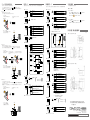
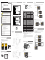
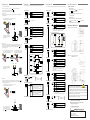
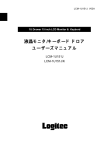
*English manual is on flip side
入出力回路図
高精度判別センサ
仕様
信号線の回路図は以下のようになります。
NPN/PNP 出力は本体の設定で切り替えられます。
BGS-HL シリーズ
茶 :+V
BGS-HL25T □□
取扱説明書
●お買い上げいただきありがとうございます。ご希望通りの製品であることをご確認ください
●取扱説明書(本書)は、ご使用前によくご確認いただき大切に保管してください
たは重症を負う可能性が想定される内容を示します。また、
接続形態 ●なし :コード式
●C :M8コネクタ式*
最大検出距離(cm)
3.3V
灰
:外部入力
青
:0V
茶 :+V
内
部
回
路
警 告
●この商品の光源は可視光半導体レーザを使用しています。レーザ光が直接または鏡面体
に反射して目に入らないようにご注意ください。目に入ると失明する恐れがあります。
●この商品は防爆構造ではありませんので、引火性または爆発性ガス、液体の環境下では
使用しないで下さい。
黒
:制御出力
灰
:外部入力
型式
検出距離
電源電圧 12~24V
表示灯
●この商品は分解したときに自動的にレーザ放射を停止する機能を備えておりませんので、
分解・改造をしないで下さい。
●この商品は人体保護を目的とした安全機器として、ご使用いただけません。
■コネクタのピン配置
(センサ側)
●適切に使用しない場合、人体への障害、火災、感電の原因になります。
デジタル表示
制御出力
・M8 コネクタ
(受注生産品)
白
出力モード
外部入力
黒
タイマ機能
注 意
茶
●電源が入ったままの配線作業は危険です、必ず電源を切ってから行って ください。
●次のような場所への設置は誤動作の原因となる事がありますのでご注意ください。
1. ホコリ・蒸気等の多い場所。
2. 腐食性ガスの発生する場所。
3. 水 ・ 油等が直接飛散する場所。
4. 振動・衝撃等の激しい場所。
接続形態
定格
青
耐環境性
外形寸法図
■コード式
●屋外での使用は避けてください。
[mm]
.8.28 size ●電源投入時(約
29×19.6 R0.62s)0567150
SICK OPTEX
の過渡状態でのご使用は避けてください。
2013.8.28 size
29×19.6 R0.6 0567140 SICK OPTEX
●高圧線や動力線との配線は別配線としてください。 誘導による誤動作や破損の原因とな
2013.8.28 size 14×26 R0.5 0567160 SICK OPTEX
ります。
質量
●水中では使用しないでください。
●定格の範囲内で使用してください。
EN/IEC 60825-1:2007
Complies with 21 CFR
1040.10 and 1040.11
except for deviations
pursuant to laser notice
No.50, dated June 24, 2007
φ 0.8 mm
φ 1 mm
最小 1.5ms ※初期設定時 1.5~7ms 最小 1.5ms ※初期設定時 3~14ms
0 ~ 22.49 (初期値 0.15)
0 ~ 149.9 (初期値 1.0)
ティーチ式 ( ティーチ後マニュアル調整可能 )
1 点ティーチ、2 点ティーチ、ゾーンティーチから選択可能
レーザ放射表示灯 ( 緑)
出力表示灯 ( 橙 )/ モード表示灯 ( 赤 )
7 セグメント 4 桁 LED
オープンコレクタ(NPN/PNP 機能内切換)
100mA max./DC24V 残留電圧 1.8V
ライト ON/ ダーク ON 機能内切替
レーザ放射停止 , ティーチ , サンプルホールド , ワンショットか
ら選択
なし / オンディレイ / オフディレイ / ワンショット から選択
(1ms 単位)
コード式:コード長 2m / コネクタ式
DC12 ~ 24V リップル(p-p)10%含む
40mA 以下
逆接続保護、過電流保護
IP67
-10 ~ 50℃ / 35 ~ 85% RH(氷結・結露なきこと)
-20 ~ 60℃ / 35 ~ 85%/RH
白熱ランプ : 5,000 lx 以下
10 ~ 55Hz、複振幅 1.5mm、X,Y,Z 各方向 2 時間
500m/s2 ( 約 50G) X,Y,Z 各方向 3 回
ケース:アルミダイカスト 前面カバー:PPSU ディスプレイ:PET
コード:耐油 PVC
約 90g ( コード式 )/ 約 30g (M8 コネクタ式)
周囲温度 23℃(常温)
、電源電圧 DC24V、サンプリング周期 500µs、平均回数 512 回、
測定箇所:測定中心距離(BGS-HL05T(C)1:35mm、BGS-HL25T(C)2:150mm)
測定対象物:弊社標準ワーク(白セラミック板)
CLASS 1 LASER
PRODUCT
MAX. OUTPUT 390μW
WAVELENGTH = 655nm
Complies with 21 CFR 1040.10 and 1040.11
except for deviations pursuant to
laser notice No.50, dated June 24, 2007
OPTEX FA CO.,LTD.
EN/IEC 60825-1:2007
Place of manufacture :
OFROM CO.,LTD.
Manufactured in
表示値の表示可能範囲は下記の通りです。
・BGS-HL05 -7.50 ~ 37.50
・BGS-HL25 -50.0 ~ 250.0
検出距離範囲内でも、表示範囲を超えると FFFF と表示します。
(FFFF 表示中も検出動作は続けます)
検出距離範囲外は 9999 表示となります。
※ 2 サンプリング周期:1000µs 時
※ 3 応差設定:0.02(BGS-HL05)
、0.2(BGS-HL25)時
※ 4 CLASS1 タイプも製作可能です(受注生産品)
。
※ 5 最大検出距離において中心強度の 1/e2(13.5%) で定義しています。規定のスポットサイズ以外に漏れ光
があり、検出距離範囲付近周囲に反射率の高いものがある場合は、その影響を受けることがあります。
※ 6 制御出力の負荷電流は含まず。
■レーザーラベルについて
この商品は可視光レーザービームを放射しており、JIS C6802 / IEC レーザー安全規格のクラス 1 または
scale 1/1
scale 1/1
scale 1/1
クラス2(Ⅱ)に相当します。製品には規格に沿ったシールが貼り付け・または添付されています。
●米国
機器搭載して米国へ輸出する場合、米国のレーザー規制FDA (Food and Drug Administration) を受け
ます。この商品は CDRH (Center for Devicesand Radiological Health) に届出済みです。米国へ輸出され
る場合は、同梱のシールを製品に貼り付け、または貼り替えてください。
「+」
「-」キーで設定項目の選択と、設定値の調整を行います。
「SET」ボタンで確定します。
「TEACH/RUN」ボタンを押すと検出モードに戻ります。
項目選択
-
パラメータ設定
+
-
+
SET
ティーチ
検出モードで「TEACH/RUN」ボタンを押すとしきい値を調整できます。
しきい値の調整は、現在位置をしきい値として設定する「ティーチ」と、しきい値を直接数値設定する
「マニュアル調整」の 2 種類があります。
ボタンを押す時間によって、
「ティーチ」か「マニュアル調整」かを選択できます。
短押し(~2秒)
しきい値を
直接数値で
設定
CLASS 1 LASER
PRODUCT
BGS-HL シリーズの各部名称です
Complies with 21 CFR 1040.10 and 1040.11
except for deviations pursuant to
laser notice No.50, dated June 24, 2007
MAX. OUTPUT 1mW
WAVELENGTH = 655nm
MAX. OUTPUT 390μW
WAVELENGTH = 655nm
EN/IEC 60825-1:2007
コード(最小曲げR=10mm)
※ 引出し口からは30mm未満は
曲げずにご使用ください
OPTEX FA CO.,LTD.
EN/IEC 60825-1:2007
91 Awata-cho Chudoji Shimogyo-ku Kyoto 600-8815 JAPAN
Complies with 21 CFR
1040.10 and 1040.11
except for deviations
pursuant to laser notice
No.50, dated June 24, 2007
Place of manufacture :
OFROM CO.,LTD.
Manufactured in
取付穴(M3×2)
※締め付けトルク 0.5N・m以下
投受光面
scale 2/1
同梱品の確認
●操作パネル
開梱後、下記製品が入っていることを確認してください。
scale 2/1
・取扱説明書(本書)
OUT :出力ON時点灯
・取り付け用ネジ
M3 × 25…2 本
再校正
・取付金具
再校正
再校正
長押し(2秒~)
現在位置を
ティーチ
2点ティーチ時
「2pt」と測定値
を交互表示
各部名称
操作パネル
・BGS-HL □□
scale 2/1
●設定方法(
「設定モード」
「詳細設定モード」時)
公称断面積 0.23mm2 [AWG24]
■ M8 コネクタ式(受注生産品)
Complies with 21 CFR
1040.10 and 1040.11
except for deviations
pursuant to laser notice
No.50, dated June 24, 2007
詳細設定
モード
※ 1 シフト機能 ON 時は、ティーチ位置を 0 として表示します。
91 Awata-cho Chudoji Shimogyo-ku Kyoto 600-8815 JAPAN
Complies with 21 CFR
1040.10 and 1040.11
except for deviations
pursuant to laser notice
No.50, dated June 24, 2007
レーザー使用に関する注意事項
CLASS 2 LASER
PRODUCT
設定モード
記載無き項目の測定条件は以下の通りとします。
●商品の分解、修理・改造をしないで下さい、人体への障害・火災・感電の原因になります。
CLASS 2 LASER
PRODUCT
電源電圧
消費電流※ 6
保護回路
保護構造
使用周囲温度 / 湿度
保管周囲温度 / 湿度
使用周囲照度
耐振動
耐衝撃
材質
●商品個々のばらつきや、対象物の状態によって検出特性に違いが生じることがあります。
MAX. OUTPUT 1mW
WAVELENGTH = 655nm
BGS-HL05T(C)
BGS-HL25T(C)2
20 ~ 50mm
50 ~ 250mm
( 表示値※ 1:0.00 ~ 30.00)
( 表示値※ 1:0.0 ~ 200.0)
0.01mm( 表示値 0.01)
0.1mm( 表示値 0.1) ※ 2
0.08mm
0.8mm
赤色半導体レーザー 波長:655nm
390 µW
1mW
CLASS 1
CLASS2 ※ 4
繰り返し精度
最小検出段差※ 3
光源
種類・波長
最大出力
レ - ザ ク IEC/JIS
ラス
スポット径※ 5
応答時間
応差距離
検出距離調整
:0V
青
測定モード
*:受注生産品
●仕様
■ PNP 出力設定時
重大な物的損害を受ける恐れがあります。
BGS-HL シリーズには「検出モード」
、
「設定モード」
、
「詳細設定モード」の三つのモード
があります。どのモードの際も
「TEACH/RUN」
ボタンを押すと必ず検出モードに戻ります。
また「詳細設定モード」時には「MANUAL」LED が点灯します。
レーザクラス ● なし:クラス1
● 2 :クラス2
電源電圧 12~24V
:制御出力
黒
0566461
この表示を無視して誤った取り扱いをすると、人が死亡ま
●モードと遷移方法
BGS-HL _ _ T _ _
BGS-HL05T □
警 告
BGS-HL シリーズのモードの種類と、モード間の遷移方法について説明します
●型式命名規則
■ NPN 出力設定時
内
部
回
路
モードと基本操作
MANUAL:詳細設定モード時点灯
LASER :レーザ放射時点灯
■短押し(~ 2 秒)
「TEACH/RUN」ボタンを短く押す(2 秒未満)と検出値が点滅します。
「+」
「-」キーでしきい
値を設定してください。
設定後は「SET」キーを押してしきい値を確定します。
「TEACH/RUN」ボタンを押すと設定内容
をキャンセルします。
■長押し(2 秒~)
「TEACH/RUN」ボタンを長押し(2 秒以上)するとティーチが実行されます。ティーチ時の動作
については「ティーチ方法と動作の違い」を参照してください。ティーチ方法の変更方法につい
ては「設定モード」を参照してください。
ティーチ方法と動作の違い
設定モード
BGS-HL シリーズには 3 つのティーチ方法があります。
検出モードから「SET」キーを押すと、設定モードに移行します( * は各設定項目の初期値)
ティーチ方法はあらかじめ「設定モード」の「ティーチ方法 tch 」から設定してください。
出力は設定モードの「ダークオン・ライトオン切替 Ldon 」の設定により ON/OFF を反転できます。
下記は「 L on ライトオン」設定時の動作です。
1Pt
ZonE
2Pt
SET
diSP
1点ティーチ
ゾーンティーチ
*
2点ティーチ
■2:詳細設定モード
NEnu
TEACH
RUN
(詳細設定モードに移行)
ShiF
oFF
LSr
tch
S h
onE
SET
+
-
ティーチ
位置 ・1 点ティーチの動作
ティーチした位置を基準に、それより
近づくと出力が ON します。
しきい値
*
外部入力を使用しません
レーザオフ : 入力中はレーザ放射を停止
*
ディスプレイを表示する
キーロック時にディスプレイを表示しない
SET
YES
no
初期化する (検出モードに戻った際に初期化)
●キーロックを解除する
初期化しない
uLoc
キーロック中に を同時に長押し(3秒以上)すると、 が表示されます。
+ -
この表示以降キーロックは解除され、全ての操作を受け付けます。
SET
on
oFF
使用する(ティーチ位置を0とする)
*
使用しない
※ ティーチ時にティーチ位置が「0」となるよう検出値をシフトし
ます。2点ティーチ時は2点のティーチ位置のうちセンサヘッド
に近い側を「0」に設定します。
ティーチ入力 : 入力で現在値をしきい値として設定
シフト機能の動作例(BGS-HL25/一点ティーチ時)
ワンショット : 入力後、次の入力まで検出値を保持
Loc
+ -
RUNモード中に を同時に長押し(1秒以上)すると、 が表示されます。
TEACH
※設定モード中の場合は、 を押すとRUNモードに移行します。
RUN
+
-
サンプルホールド : 入力中は検出値を保持
●キーロックを設定する
この表示中は、「キーロック解除」以外の操作を全て無視します。
■2:初期化
■3:シフト機能
■3:外部入力
inP
on
oFF
+
-
+
-
1Pt
SET
+
-
rESt
SET
その他の便利な機能について説明します
■キーロック機能
■1:ディスプレイ表示
+
-
「1Pt」と表示され、ティーチが完
了します
その他の機能
設定モードの「Menu」を選択すると、詳細設定モードに移行します( * は各設定項目の初期値)
■1:ティーチ方法
tch
●1点ティーチ
検出するワークを置いてティーチします。
ティーチ位置、またはより近い位置でセンサが ON します。
・ティーチの流れ
ワークを置き、「TEACH/RUN」キー
を長押しします
詳細設定モード
200.0
初期値
外形寸法図(取付金具装着時)
[mm]
■コード式(付属の BGS-HL-B 使用時)
0.0
■4:出力ディレイ時間
tiNE
ON
OFF
hYSt
検出距離
dELy
2 点ティーチ時に同一地点を指定すると、エラー( Err )を表示し、ティーチを中断します。
ワークを置き、
「TEACH/RUN」 「1Pt」 と 表 示 さ れ た 後、
「2Pt」と検出値が交互に表
キーを長押しします
示されます
TEACH
RUN
0000
ティーチ位置
off
ofdy
ondy
shot
SET
+
-
ワークを取り「TEACH/RUN」を押すと、
「2Pt」と表示されティーチが完了しま
す
off
2Pt
1Pt
ofdy
0.123
・2点ティーチの動作
ティーチした二点の中心位置を基準に、
それより近づくと出力が ON します。
ティーチ
位置1 ティーチ
位置2 オンディレイ
shot
■4:平均回数
ワンショット
AUG
ON
OFF
thrE
ON
OFF
OFF
「1Pt」と表示され、ティーチが完
了します
TEACH
RUN
+
-
SET
+
-
BGS-HL05□□ 03.00
BGS-HL25□□ 020.0
SANP
ライトオン:しきい値より近くで出力がONします
SET
L on (ゾーンティーチ時は基準距離から外れるとON)
検出範囲外では出力はOFFします
*
SET
+
-
ダークオン:しきい値より遠くで出力がONします
D on (ゾーンティーチ時は基準距離の近くでON)
■8:応差距離
hYSt
感度1 : 感度を最小値で固定します
500
1000
2000
4000
Auto
500 µs (2kHz)
n_P
+
-
ON
OFF
hYSt
*
*
1000 µs (1kHz)
2000 µs (500Hz)
4000 µs (250Hz )
AUTO
(※)
SET
0.123 (数値直接入力) 初期値:
BGS-HL05□□ 0.15
BGS-HL25□□ 1.0
● 製品の仕様は改良のため予告なく変更することがあります
● 製品に関するお問い合わせ、ご意見等は製造・販売元の下記
までご連絡ください
■9:電気出力特性
toL
検出距離
感度6 : 感度を最大値で固定します
N__1
+
-
基準位置
*
Auto : 感度を自動調整します
BGS-HL25の初期値は1000 µsです。
※2 AUTO設定時は最適なサンプリング周期を
センサがリアルタイムに調整します。
■1:ティーチ方法へ(ループします)
hYSt
Auto
N__6
※1 BGS-HL05の初期値は500µs、
1Pt
・ゾーンティーチの動作
ティーチした位置を基準に、
一定距離離れると ON します。
レベル100 : 波形の低い位置に基準を設定
■7:サンプリング周期
検出範囲外では出力がONします
ティーチ
位置 ■コネクタ式(付属の BGS-HL-A 使用時)
レベル200 : 波形の中程に基準を設定
■6:感度
■7:ダークオン・ライトオン切替
Ldon
・ティーチの流れ
ワークを置き、「TEACH/RUN」キー
を長押しします
*
ベース面 :波形の最も低い面に基準を設定
レベル400 : 波形の高い位置に基準を設定
乱反射により測定が不安定な際に、レベルを変えることで検出が
安定する場合があります。
通常は変更しないでください。
ON
0.123 (数値直接入力) 初期値:
+
-
bASE
P400
P200
P100
~
ワークがない状態でティーチを行います。
ワークが進入し、ティーチを行った点から「ZONE 動作距離 toL 」で設定した距離以上検出値が変化
するとセンサが ON します。
基準位置(コンベアなど)を基準として、ワークが来ると検出する場合に使用します。
(FGS モード)
SET
64回
512回
※ どれだけ受光すれば検出値として認識するかを設定します。
■6:ZONE動作距離
●ZONE ティーチ
SET
+
-
SEns
toL
*
1回
8回
■5:スレッシュホールド
ON
OFF
tiNE
hYSt
1
8
64
512
SET
+
-
ON
OFF
検出距離
-35.00
検出距離
tiNE
しきい値
000.0
165.0
オフディレイ
tiNE
ondy
ティーチ後
*
なし
各選択項目ごとの動作の違い
TEACH
RUN
2Pt
(数値入力:単位ms)
■5:出力ディレイ
●2点ティーチ
検出するワークを用意してティーチします。
ティーチした二点の中間地点にしきい値が引かれ、その位置より近いとセンサが ON します。
・ティーチの流れ
SET
+
-
SET
nPn
PnP
入出力がNPNで動作します
入出力がPNPで動作します
※初期化(reset)操作を行っても変更されません
■1:ディスプレイ表示へ(ループします)
*
本 社 〒 600-8815 京都府京都市下京区中堂寺粟田町 91
京都リサーチパーク内
TEL 075-325-2920 FAX 075-325-2921
オプテックス・エフエーホームページ
http://www.optex-fa.jp
Specifications
Connection diagram
● Part number legend
High resolution BGS sensor
■ NPN type
Brown :+V
BGS-HL05T □
BGS-HL25T □□
- Thank you for purchasing BGS-HL series. We hope you are satisfied with its performance.
- Please read this manual carefully and keep it for future reference.
DC 12~24V
Black :Control Output
Main Circuit
Instruction manual
Gray
Blue
:External Input
Cable type
Part
number Connector type
Sensing range ※ 1
:0V
Laser
IEC/JIS
class
※2
Spot size
Repeat accuracy
Sampling period
Response time
Hysteresis
Display
Indicator
■ PNP type
● The light source of this product applies the visible light semiconductor laser. Do not
allow the laser beam to enter an eye, either directly or reflected from reflective object. If
the laser beam enters an eye, it may cause blindness.
DC 12~24V
Brown :+V
Main Circuit
● Do not disassemble or modify the product since it is not designed to automatically stop
the laser emission when open. Disassembling or modifying at customer's end it may
cause personal injury, fire or electric shock.
●Use of controls or adjustments or performance of procedures other than those specified
herein may result in hazardous radiation exposure.
Black :Control Output
Gray :External Input
Blue
Safety Precautions
● It is dangerous to wire or attach/remove the connector while the power is on. Make sure
to turn off the power before operation.
■ Pins configuration
( sensor side )
● Installing in the following places may result in malfunction:
1. A dusty or steamy place
2. A place generating corrosive gas
3. A place directly receiving scattering water or oil.
4. A place suffered from heavy vibration or impact.
Control Output
External Input
Timer function
:0V
Supply voltage
Current consumption
Protection circuit
Protection category
Operating Temp./Humid.
Storage Temp./Humid.
Ambient illuminance
Vibration resistence
Shock resistence
Material
Weight
・M8 connector type
White
Brown
● The product
designed for
outdoor
use.
8.28 size 29×19.6
R0.6is not
0567150
SICK
OPTEX
2013.8.28 size 29×19.6 R0.6 0567140 SICK OPTEX
Black
Blue
● Do not use the sensor in a transient state at power on (Approx. 2sec. Warm up period)
● Do not wire with the high voltage cable or the2013.8.28 size
power lines. Failure 14×26
to do this
will cause
R0.5
0567160 SICK OPTEX
malfunction by induction or damage.
Dimensions
● Do not use the product in water.
■ Cable type
● Operate within the rated range.
[mm]
CLASS 2 LASER
CLASS 1 LASER
● Wipe PRODUCT
off dirt on the emitting/receiving
parts to maintain correct detection. Also, avoid
PRODUCT
direct
impact on the product.
EN/IEC 60825-1:2007
Complies with 21 CFR
1040.10 and 1040.11
except for deviations
pursuant to laser notice
No.50, dated June 24, 2007
MAX. OUTPUT 390μW
WAVELENGTH = 655nm
Complies with 21 CFR 1040.10 and 1040.11
except for deviations pursuant to
laser notice No.50, dated June 24, 2007
EN/IEC 60825-1:2007
Complies with 21 CFR
1040.10 and 1040.11
except for deviations
pursuant to laser notice
No.50, dated June 24, 2007
OPTEX FA CO.,LTD.
91 Awata-cho Chudoji Shimogyo-ku Kyoto 600-8815 JAPAN
Place of manufacture :
OFROM CO.,LTD.
Manufactured in
scale 1/1
scale 1/1
Emitter axis
Precautions for using laser
● Regulations in the USA
When exporting laser devices to the USA, the USA laser control, FDA
(Food and Drug Administration) is applied. This product has been already
reported to CDRH (Center for Devices and Radiological Health). For
details, contact our customer service.
Connect type
●(none) :Cable
●C :M8 Connector
● Specifications
Light source
● This product is not an explosion proof construction. Do not use the product under flammable , explosive gas or liquid environment.
●(none):Class 1
● 2
:Class 2
scale 1/1
BGS-HL05T
BGS-HL25T2
BGS-HL05TC
BGS-HL25TC2
20 ~ 50mm
50 ~ 250mm
(Display: 0.00 ~ 30.00)
(Display: 0.0 ~ 200.0)
Red laser Diode (wave length 655nm)
390µW
1mW
CLASS 1
CLASS 2
φ 0.8 mm @ 50mm
φ 1 mm @ 250mm
10µm
100µm ※ 3
500µs / 1000µs / 2000µs / 4000µs / AUTO
1.5ms max. (1.5~7ms/default)
1.5ms max. (3~14ms/default)
0 ~ 22.49 (default: 0.15)
0 ~ 149.9 (default: 1.0)
7-segment 4-digit LED display
Laser indicator: Green,
Output indicator: Orange, Mode indicator: Red
NPN/PNP selectable
100mA max./DC24V (Residual voltage 1.8 V max.)
Laser OFF, Teaching, Sample Hold, One shot hold
OFF/On delay/Off delay/One shot
1msec increment : 0 ~ 9999ms
12 ~ 24VDC including 10% ripple
40mA max. / 24VDC excluding the current of Control Output
Reverse connection protection, Over current protection
IP67
-10 ~ 50℃ / 35 ~ 85% RH without freasing or condensation
-20 ~ 60℃ / 35 ~ 85%/RH
Incandescent lamp: 3,000 lx max.
10 ~ 55Hz, Double amplitude 1.5mm, X,Y,Z for 2 hours
500m/s2 ( approx. 50G) X,Y,Z 3 times each
Case: Aluminum, Front lens: PPSU, Display: PET
Cable type : Approx. 90g (including cable)
Connector type : Approx. 30g
The specifications are based on the condition unless otherwise designated: Ambient temperature: 23℃ , Supply voltage: 24VDC, Sampling period: 500µs, Averaging: 512, Measuring distance: Center of the range, Testing
object: White ceramic
※ 1 When [Shift] in Extension mode is ON, the display shows 0000 at the Teaching point.
The range that the display can show is as follows.
BGS-HL05 -7.50 ~ 37.50
BGS-HL25 -50.0 ~ 250.5
When the distance exceeds this range in Sensing range, the display shows FFFF. Although, the sensor
works while the distance is in Sensing range. The display shows 9999 when the distance is out of range.
※ 2 Defined by light strength within 1/e2(13.5%) of spot center. There may be leak light at outside of the
specified spot size. The sensor may be affected when there is a highly reflective object at that leak light
area.
※ 3 Sampling period : 1000µs.
MAX. OUTPUT 1mW
WAVELENGTH = 655nm
MAX. OUTPUT 390μW
WAVELENGTH = 655nm
EN/IEC 60825-1:2007
Complies with 21 CFR
1040.10 and 1040.11
except for deviations
pursuant to laser notice
No.50, dated June 24, 2007
EN/IEC 60825-1:2007
Complies with 21 CFR
1040.10 and 1040.11
except for deviations
pursuant to laser notice
No.50, dated June 24, 2007
OPTEX FA CO.,LTD.
■ M8 connector type
Holes for installation
(M3 * 2)
* Tightening torque must be
0.5N・m Max.
● Control panel
Emitter axis
scale 2/1
・Screws
M3 × 15…2
Display
OUT :ON when output is ON
再校正
・Bracket
再校正
You can choose and adjust the parameters by clicking "+" and "-" buttons.
The mode will be changed to "RUN mode" by clicking "TEACH/RUN" button.
Changing
parameter
-
Adjusting
parameter
+
-
+
SET
Teach function
You can change threshold level directly by “+” and “-” buttons after clicking “TEACH/
RUN” button from “RUN mode”.
By pressing “TEACH/RUN” button for 2 seconds or more, it gets to “Teaching mode”. It
has 3 “Teaching mode” that you can choose one in “Setup mode”.
Please refer “Teaching mode” and “Setup mode” on next page.
Click
Change
threshold
level directly
Click
Teach current
position
When it is "2pt teaching mode"
Click
RUN mode
91 Awata-cho Chudoji Shimogyo-ku Kyoto 600-8815 JAPAN
Place of manufacture :
OFROM CO.,LTD.
Manufactured in
scale 2/1
・This instruction
scalemanual
2/1
● Changing parameters
φ4.5 4core 2m Cable
Complies with 21 CFR 1040.10 and 1040.11
except for deviations pursuant to
laser notice No.50, dated June 24, 2007
Please confirm following goods bundled in the box.
・BGS-HL□□□□
Extension mode
Cable (minimum bending radius : 10mm)
Lens (Emitter/Receiver)
Bundled goods in the box
Setup mode
Functions of components
* Don't bend the cable of the outlet
part up to 30mm from the case.
CLASS 1 LASER
PRODUCT
RUN mode
Press 2 seconds
or more
Display
Control panel
CLASS 2 LASER
PRODUCT
While it's "Setup mode" or "Extension mode", you can change the mode to "RUN mode"
by clicking "TEACH/RUN" button.
While it's "Extension mode", the LED "MANUAL" is lit.
3.3V
injury, WARNINGS or serious property damage if the product is
used without observing the stated instructions.
Warning Mandatory Requirements
Laser Class
Working distance(cm)
Indicates a possible hazard that may result in death, serious
MAX. OUTPUT 1mW
WAVELENGTH = 655nm
● Changing mode
BGS-HL _ _ T _ _
BGS-HL Series
Warning
Setup
再校正
MANUAL:ON when "Extension mode"
M8 4pin
Connector
LASER : ON when laser is emitted
Displays "2pt"
and current
position
alternately
Teaching mode
Setup mode
Extension mode
You can get to [Setup mode] by clicking "SET" button from [RUN mode]. (* means default value)
BGS-HL series has 3 Teaching mode.
● Activate Key lock
] in [Setup mode] before Teaching.
Output polarity can be reversed by [Light ON/Dark ON Ldon ].
Following output shows its ON/OFF status as [Light ON L on ].
tch
● 1 point Teaching
Teaching is done at a position on the object to detect. When the distance is closer than that position,
the output will be ON.
+
-
1Pt
ZonE
2Pt
diSP
1point teaching
ZONE teaching
*
2point teaching
NEnu
SET
To Extension mode
1Pt
When the distance is closer than the
Teach position in Sensing range, the
output will be ON.
inP
threshhold
+
-
ON
OFF
oFF
LSr
tch
S h
onE
tiNE
hYSt
*
OFF : Disable external input
SET
+
-
dELy
SET
+
-
off
ofdy
ondy
shot
Teaching : Set current value as threshold
2Pt
off
2Pt
1Pt
0.123
ofdy
One shot hold: Hold the value as input turns ON
Teach
position 2
ondy
threshhold
When the distance is closer than the
Teach position in Sensing range, the
output will be ON.
lock" will be neglected.
Initialize the parameters to default setting
● Release Key lock
While Key lock is activated, it will be released by pressing
Do nothing
+ -
at a time for 3 seconds. Then,
on
oFF
Activate(Set teach position as "0000")
*
Not use
Before
Teaching
200.0
*
OFF : Disable output delay
After
Teaching
165.0
Teach
position
Dimensions with bracket
AUG
One shot
SET
+
-
ON
OFF
● ZONE Teaching
Teaching is done without object to detect. Teach position will be set at this position. When the distance
between the object and Teach position gets bigger than the distance set at [ZONE distance toL ] in
[Setup mode], the output will be ON.
0.123
thrE
SET
OFF
+
-
ON
OFF
ON
OFF
■6:Sensitivity
SET
+
-
Set the value Default:
bASE
P400
P200
P100
Auto
N__6
N__1
■7:Light ON/Dark ON selection
SET
L on
TEACH
RUN
D on
■1:Teaching mode (Loop)
SANP
Light ON: When the distance is closer than
Threshold. the output will be ON. (ZONE Teach
mode: When the distance is outside of ZONE
distance, the output will be ON.)
While it's out of range, the output will be OFF.
Dark ON: When the distance is farther than
Threshold. the output will be ON. (ZONE Teach
mode: When the distance is inside of ZONE
distance, the output will be ON.)
While it's out of range, the output will be ON.
*
SET
+
-
φ4.5 4core 2m Cable
64 times
■ Connector type with standard bracket BGS-HL-A
512 times
Base :Set threshold to lowest level
P200 :Set threshold to middle level
P100 :Set threshold to lower level
Auto : Adjust sensitivity automatically
n_P
SET
1 : Minimum sensitivity
M8 4pin
Connector
500 µs (2kHz)
1000 µs (1kHz)
*
*
2000 µs (500Hz)
4000 µs (250Hz )
AUTO
0.123
Set the value
Default:
BGS-HL05□□ 0.15
BGS-HL25□□ 1.0
Attention: Not to be Used for Personnel Protection.
Never use these products as sensing devices for personnel protection. Doing
so could lead to serious injury or death. These sensors do not include the
self-checking redundant circuitry necessary to allow their use in personnel
safety applications. A sensor failure or malfunction can cause either an energized or de-energized sensor output condition.
Please consult our distributors about safety products which meet OSHA,
ANSI and IEC standards for personnel protection.
● Specifications and equipment are subject to change without
any obligations on the part of manufacture.
SET
+
-
toL
*
6 : Maximum sensitivity
■9:NPN/PNP selection
threshhold
*
P400 :Set threshold to upper level
Default: 500 µs ( BGS-HL05 )
1000 µs ( BGS-HL25 )
Auto: The sensor optimize sampling period automatically.
■8:Hysteresis
hYSt
500
1000
2000
4000
Auto
+
-
Teach
position
8 times
■7:Sampling period
+
-
1Pt
*
Once
Set threshold level to detect rising part and falling part of light
strength wave. You can change the threshold level especially
when the sensor receives external light as noise so to get
stable detection.
Basically, you don't have to change the threshold.
BGS-HL05□□ 03.00
BGS-HL25□□ 020.0
+
-
Ldon
Press the [TEACH/RUN] button until the display shows “1pt”.
Teaching is completed after releasing button.
SET
1
8
64
512
~
toL
-35.00
■5:Treshold
ON
■6:ZONE distance
Sensing range
[mm]
■ Cable type with standard bracket BGS-HL-B
Sensing range
SEns
hYSt
will be shown.
0.0
■4: Averaging
On delay
tiNE
ON
OFF
000.0
Off delay
tiNE
shot
uLoc
Set the value (unit : ms)
tiNE
Teach
position 1
While Key lock is activated, any access except "Release Key
Example of 1 point Teaching (BGS-HL25)
Sample hold : Keep the level when input is ON
How each mode works
TEACH
RUN
at a time for 1 second.
Set the display "0000" at the Teach position (threshold) when
Teaching is done. When it's 2 point Teaching, set the display
"0000" at near side position of 2 positions of Teaching.
Laser OFF : Kill laser power when input is ON
■5:Output delay
Click the [TEACH/RUN] button without
object to detect. Then, the display shows
“2pt“ that means Teaching is completed.
TEACH
RUN
0000
+ -
will be shown.
+
-
● 2 point Teaching
Teaching is done at two different positions on the object to detect. Teach position will be set at center
of these two positions. When the distance is closer than the Teach position, the output will be ON.
When the distance between these two positions is too close, the display will show Err that means
error. Then, please try again.
Press the [TEACH/RUN] button until the display
shows “1pt”. Then, the display shows “2pt“ and
the distance related number alternately.
SET
YES
no
Loc
Then,
After this process, every access will be accepted.
ShiF
SET
*
Activate the display
Disable the display while "Key lock"
Initializing will be done when the mode gets to RUN mode.
SET
■4:Delay time
Sensing range
When the distance between the
object and Teach position gets bigger than the distance set at [ZONE ON
OFF
distance toL ], the output will be
ON.
■2:Reset (Initializing)
■3:Shift function
■3:External input
Teach
position
on
oFF
+
-
+
-
+
-
TEACH
SET
rESt
■2:Extension mode
Press the [TEACH/RUN] button until the display shows “1pt”.
Teaching is completed after releasing button.
RUN
SET
While it's RUN mode, press
■1:Display setting
■1:Teaching mode
Emitter axis
tch
■ Key lock function
Emitter axis
Please choose a Teaching mode at [Teach mode
Miscellaneous function
You can get to [Extension mode] from [2:Extension mode] in [Setup mode]. (* means default value)
nPn
PnP
Set input/output as NPN
*
● For more information, questions and comments regarding
products, please contact us below.
Set input/output as PNP
This parameter won't be changed by [Reset]
■1:Display setting (Loop)
hYSt
hYSt
Sensing range
600-8815 Kyoto, Shimogyo, Awata Chudoji 91, Japan
TEL : +81-(0)75-325-2920
FAX: +81-(0)75-325-2921
Website : http://www.optex-fa.com