1
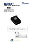
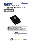
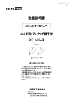
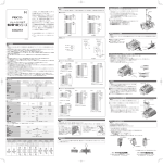
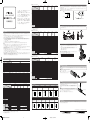
■ 15 シリーズメインバルブ
SVB15S
形式
SVB15D
SVB15A
SVB15J
SVB15Y
SVB15R
SVB15L
SVB15Z
SVB15P
SVB15M
SVB15N
項目
使用流体
この度は、ピスコ製品をお買い上げいた
だき誠にありがとうございます。
本製品をお客様に安心してお使いいただ
くために、本取扱説明書を必ずお読みく
ださい。又、本書は大切に保管していた
だきますようお願い申し上げます。
製品カタログには、ピスコ製品、及びピ
スコ電磁弁共通の取扱い上の注意事項が
記載されています。本製品のご使用にあ
たっては、製品カタログの注意事項につ
いても併せてご確認ください。
ソレノイドバルブ
SVB シリーズ
取扱説明書
空気
0.2 ∼ 0.7MPa
0.15 ∼ 0.7MPa
使用圧力範囲
●注意
1. コネクタケーブルに過大な引張力、極端な曲げ、ケーブルの繰り返し動作等は避けてください。製品の破損、ケーブル断線の原因となる可
能性があります。
2. DC24V 仕様は、サージ対策としてサージアブソーバを標準装備していますが、サージが完全に吸収されるものではありません。サージによ
る誤作動の恐れがある場合には、別途対策を施してください。
0.15 ∼ 0.7MPa
1.05MPa
耐圧
0V(黒)
使用温度範囲
5 ∼ 50ºC
取付方向
自由 ( ※ 1)
作動方式
パイロットバルブによる間接作動
(∼)青
M5 × 0.8(※ 2)
ポートネジサイズ
弁構造
弾性体シール、スプール弁
2 ポジション
ポジション数
3 ポジション
5 ポート
ポート数
+24V(赤)
2 ポジション
(∼)青
3 ポート
弁機能
シングル
ダブル
シングル
ダブル
応答時間
15msec
12msec
15msec
12msec
DC24V
AC100V, AC110V, AC200V, AC220V
5Hz
最高作動頻度
50msec
最小励磁時間
50msec
給油
0V(Black)
不要
流量特性
1(P) → 4(A)
C ( ※ 3)
0.68
S ( ※ 4)
3.4 (0.18)
中立位置
0.74
C ( ※ 3)
0.64
S ( ※ 4)
3.2 (0.17)
(∼)Blue
0.68
3.7 (0.20)
3.4 (0.18)
製品固定方法
●警告
+24V(Red)
1. ソレノイドバルブを 49m/s2 以下の振動の中で使用する場合、振動方向がスプール弁に対し直角になるように取付けてください。(49m/s2 以
下の振動でご使用ください。)
(∼)Blue
※ 1. 製品固定方法を参照してください。
※ 2: SVB15J・L・Y は、マニホールド搭載専用バルブの為、1(P)・5(R1)・3(R2) ポートはネジ加工がありません。
※ 3. C:音速コンダクタンス C (dm3/(s・bar))
※ 4. S:有効断面積 S (mm2 (CV 値 ))
HIR0042-00
電気回路図
■ 18 シリーズメインバルブ
注意事項
SVB18S
形式
SVB18D
●警告
SVB18Z
SVB18P
SVB18M
SVB18N
項目
使用流体
空気
0.2 ∼ 0.7MPa
0.15 ∼ 0.7MPa
使用圧力範囲
0.15 ∼ 0.7MPa
1.05MPa
耐圧
使用温度範囲
5 ∼ 50ºC
取付方向
自由 ( ※ 1)
作動方式
パイロットバルブによる間接作動
Rc1/8 ( ※ 2)
ポートネジサイズ
弁構造
弾性体シール、スプール弁
20msec
15msec
5Hz
50msec
50msec
不要
1(P) → 4(A)
C ( ※ 3)
2.6
2.6
2.6
S ( ※ 4)
13 (0.70)
13 (0.70)
13 (0.70)
中立位置
C ( ※ 3)
1.04
S ( ※ 4)
5.2 (0.28)
■マニホールド固定ネジ締付け推奨トルク
バルブをマニホールドに取付ける際、下記推奨締付けトルクに従い締付けを行ってください。
推奨以外での締付けは、緩み・破損の原因になります。
※ 1. 製品固定方法を参照してください。
※ 2: SVB18J・L・Y は、マニホールド搭載専用バルブの為、1(P)・5(R1)・3(R2) ポートはネジ加工がありません。
※ 3. C:音速コンダクタンス C (dm3/(s・bar))
※ 4. S:有効断面積 S (mm2 (CV 値 ))
パッキン
LOC
K
SH
PU
バルブシリーズ SVB10 シリーズ SVB15 シリーズ SVB18シリーズ SVB22シリーズ
推奨締付けトルク 0.12∼ 0.15N・m 0.25∼ 0.35N・m 0.25 ∼ 0.35N・m 0.3 ∼ 0.5N・m
CK
流量特性
Vibration
LO
最小励磁時間
給油
固定用ネジ
SH
15msec
最高作動頻度
Okay
■ソレノイドバルブをマニホールドより着脱する場合は下記の手順により行ってください。
① . プラスドライバでソレノイドバルブ固定用ネジ(2 本)を廻し、完全にバルブよりネジを外
Vibration
します。
② . ソレノイドバルブを(図 1)の矢印の方向へ真っ直ぐ引き抜いてください。
③ . ソレノイドバルブをマニホールドは取付ける場合はパッキンが確実に装着されていること
を確認してから取付けてください。
④ . 固定用ネジを締付けてください。
PU
20msec
ダブル
CK
LO
応答時間
シングル
CK
ダブル
LO
シングル
No good
ソレノイドバルブ着脱方法
3 ポート
弁機能
SH
PU
2 ポジション
SH
PU
3 ポジション
5 ポート
CK
2 ポジション
ポジション数
ポート数
LO
1. 使用圧力範囲外での使用はしないでください。使用圧力範囲を超える圧力で使用した場合には、破損、変形の危険性があります。
2. バルブは漏れを許容していますので、漏れ量がゼロを必要とする使い方では使用しないでください。
3. バルブは大容量のエアーブロー用として使用しないでください。内部パイロット型構造になっていますので内部圧力の低下により作動不良の原
因となる可能性があります。
4. 手動操作によりバルブの切換を行うと接続されたアクチュエータなどが作動します。安全を確認の上操作を行ってください。
5. 配線は必ず電源を切ってから行ってください。また、配線時には線の色を確認してください。
6. バルブは無給油で使用できますが給油される場合は、タービン油 1 種 (ISO VG32) をご使用ください。途中で給油を止めると初期潤滑剤の飛散に
より作動不良を起こすことがありますので給油は続けて行ってください。
7. バルブの各ポートを本体の刻印表示により確認し、配管を行ってください。
8. 保守、点検は電源を切り、エアーを止め、配管内の圧力がゼロになったことを確認してから行ってください。尚、3 位置クローズドセンタタイプは、
バルブとアクチュエータ間にエアーが残っていますのでご注意ください。
9. 精度を必要とするシリンダの中間停止に 3 位置バルブは使用しないでください。空気の圧縮性のため精密な位置の停止は困難です。又、バルブ
は漏れを許容していますので長時間停止位置を保持できないことがあります。
SVB18Y
SH
●注意
SVB18J
SVB18L
PU
1. 圧縮空気は、取り扱いを誤ると危険です。空気圧機器を使用した機械・装置の組立てやメンテナンスなどは、十分な知識と経験を持った人が行っ
てください。
2. 製品の保守点検等を行う場合には、供給している電源を切り、供給エアーを止め配管内の残圧を確実に排気させてから行ってください。マニホー
ルドからのユニットの着脱を行う場合にも供給エアーの停止と配管内の残圧排気は必ず行ってください。
3. 本製品は、防爆構造ではありません。引火性、爆発性のあるガス、流体、雰囲気中での使用は避けてください。
4. バルブへ下記①∼③の状態で通電をするとコイルより発熱します。発熱により製品寿命の低下、作動不具合等に繋がる可能性があります。また、
熱による火傷、及び周辺機器への影響を与える可能性もあります。下記①∼③の状態で通電される場合には、弊社営業所にご相談ください。
① . 概ね 2 時間を超える長時間連続通電。
② . ハイサイクル通電。
③ . 断続的通電でも、1 日当たりの累計通電時間の割合が、非通電時間よりも長い場合。
5. 水滴、油滴、塵埃のかかる所では使用しないでください。防滴構造ではありませんので作動不良の原因となる可能性があります。
SVB18A
SVB18R
LOC
■ 22 シリーズメインバルブ
SVB22S
形式
仕 様
SVB22D
使用流体
弁構造
弾性体シール、ポペット弁
AC90 ∼ AC110V
DC21.6 ∼ DC26.4V
許容電圧範囲
0.55W
1VA
サージアブソーバ
ブリッジダイオード
消費電力(ランプ付)
サージ保護回路
手動操作
定格電圧
DC24V
AC100V
AC110V
作動方式
AC220V
弾性体シール、ポペット弁
許容電圧範囲
消費電力(ランプ付)
サージ保護回路
DC21.6 ∼ DC26.4V
AC90 ∼ AC110V
AC99 ∼ AC121V
AC180 ∼ AC220V
AC198 ∼ AC242V
0.8W
1VA
1.1VA
2VA
2.2VA
サージアブソーバ
ブリッジダイオード
手動操作
LED
動作ランプ
弁機能
シングル
応答時間
25msec
■個別差込コネクタの装着は、止まるまで差し込む
だけでセットできます。(図 2)
■コネクタを外す場合は、コネクタのレバーを矢印
方向に押しながら引抜いてください。(図 3)
ダブル
18msec
最高作動頻度
5Hz
最小励磁時間
50msec
25msec
レバー
コネクタ裏
不要
流量特性
1(P) → 4(A)
(図2)
C ( ※ 2)
3.6
3
S ( ※ 3)
18 (0.98)
15 (0.81)
中立位置
C ( ※ 2)
2.6
S ( ※ 3)
13 (0.70)
(図3)
CK
LO
SH
PU
コネクタ
※ 1. 製品固定方法を参照してください。
※ 2. C:音速コンダクタンス C (dm3/(s・bar))
※ 3. S:有効断面積 S (mm2 (CV 値 ))
プッシュ&ロック式
コネクタ式 ( ストレート形 ( 上方取出 )、エルボ形 ( 横方取出 ))
配線取出方向
3 ポジション
5 ポート
給油
直接作動
弁構造
2 ポジション
ポート数
AC200V
●注意
1. 個別差込コネクタ(ケーブル)には、強い引張力や極端な曲げを与えないでください。断線、またはコネクタ部の破損の原因となる可能性が
あります。
弾性体シール、スプール弁
ポジション数
■ 15、18、22 シリーズパイロットバルブ
個別差込コネクタの着脱
パイロットバルブによる間接作動
1(P)・4(A)・2(B) ポート:Rc1/4、5(R1)・3(R2) ポート:Rc1/8
弁構造
LED
項目
5 ∼ 50℃
自由 ( ※ 1)
ポートネジサイズ
コネクタ式 ( ストレート形 ( 上方取出 )、エルボ形 ( 横方取出 ))
動作確認ランプ
使用温度範囲
取付方向
作動方式
プッシュ&ロック式
配線取出方向
0.3 ∼ 0.7MPa
1.05MPa
耐圧
直接作動
CK
作動方式
空気
0.2 ∼ 0.7MPa
使用圧力範囲
LO
AC100V
SH
DC24V
PU
定格電圧
(図1)
SVB22P
項目
項目
手動操作
●注意
SVB10A
SVB10D-M □
SVB10A-M □
空気
0.2 ∼ 0.7MPa
使用圧力範囲
0.3 ∼ 0.7MPa
0.2 ∼ 0.7MPa
耐圧
1.05MPa
使用温度範囲
5 ∼ 50ºC
取付方向
自由 ( ※ 1)
作動方式
パイロットバルブによる間接作動
5(R1)
1(P)
3(R2)
M5 × 0.8
弁構造
弾性体シール、スプール弁
2 ポジション
ポジション数
3 ポジション
シングルソレノイド
2 ポジション
4(A)
2(B)
12
エキゾーストセンタ
14
5(R1)
1(P)
3(R2)
4(A)
2(B)
12
3 ポジション
記号 R
5 ポート 3 ポジション
クローズドセンタ
14
5(R1)
1(P)
3(R2)
A
記号
ダブルソレノイド
14
M5 × 0.8
ポートネジサイズ
0.3 ∼ 0.7MPa
D
プレッシャセンタ
14
5(R1)
1(P)
3(R2)
4(A)
2(B)
12
P
記号
▲
使用流体
S
記号
5 ポート 2 ポジション
記号
▲
SVB10P-M □
▲
SVB10P
▲
SVB10R-M □
▲
項目
SVB10S-M □
SVB10R
14
5(R1)
1(P)
3(R2)
4(A)
2(B)
■手動操作によりバルブの切換が行えます。(パイロット圧の供給時のみ作動します。)
■時計ドライバでマニュアルボタンを止まる位置まで押し、時計方向へ回すとロックします。
ロックの解除はマニュアルボタンを半時計方向へ回すと解除されます。( 時計ドライバを回す
時のトルクは、0.05N·m以下に抑えて回してください。)
■マニュアルボタンは平常運転開始前に必ずロックを解除してください。
時計ドライバ
PUSH
ロック
解除
CK
SVB10D
バルブタイプ
LO
SVB10S
マニホールド仕様
SH
単体仕様
1. 手動操作によりバルブの切換を行うと接続されたアクチュエータなどが作動します。安
全を確認の上操作を行ってください。
2. マニュアルボタンに必要以上の力を加えないでください。破損の原因になります。
3. 10 シリーズのマニュアルカバー閉時は、マニュアルの手動操作及びロック操作ができま
せん。
PU
■ 10 シリーズメインバルブ
形式
K
K
SVB22A
SVB22R
■ 10 シリーズパイロットバルブ
K
SH
PU
LOC
SH
PU
LOC
SH
PU
マニュアルボタン
LOC
ロック
解除
4(A)
2(B)
12
K
SH
PU
PU
SH
12
5 ポート
25msec( ※ 3)
20msec
12msec
25msec( ※ 3)
5Hz
最高作動頻度
50msec
最小励磁時間
50msec
給油
J
記号
L
記号
記号
Y
記号
3 ポート 2 ポジション
M
シングルソレノイド
シングルソレノイド
ダブルソレノイド
ノーマルクローズ
ノーマルオープン
(3, 5ポート弁混合搭載マニホールド用)
(3, 5ポート弁混合搭載マニホールド用) (3, 5ポート弁混合搭載マニホールド用)
シングルソレノイド
ノーマルクローズ
N
記号
シングルソレノイド
ノーマルオープン
Z
記号
ダブルソレノイド
不要
4(A), 2(B)
流量特性
4(A), 2(B)→
5(R1), 3(R2)
0.6
0.8
0.36
0.4
S ( ※ 5)
3.0 (0.16)
4.0 (0.22)
1.8 (0.10)
2.0 (0.11)
中立位置
C (※4)
0.4
0.32
S (※5)
2.0 (0.11)
1.6 (0.09)
C ( ※ 4)
0.4
0.8
0.32
0.4
S ( ※ 5)
2.0 (0.11)
4.0 (0.22)
1.6 (0.09)
2.0 (0.11)
中立位置
C (※4)
0.4
0.24
S (※5)
2.0 (0.11)
1.2 (0.07)
12
1(P)
3(R1)
12
12
2(A)
10
1(P)
3(R1)
2(A)
10
1(P)
3(R1)
2(A)
10
1(P)
3(R1)
12
12
12
2(A)
10
1(P)
3(R1)
2(A)
10
1(P)
3(R1)
2(A)
CK
1(P) →
C ( ※ 4)
継手の締付け
■バルブ及びマニホールドに継手を取付ける際、バルブ本体又はマニホールド本体を保持し取付を行ってください。パイロットバルブを保持して
PUSH
Unlock
締付けを行うと破損する場合があります。
Lock
LO
12msec
15msec( ※ 3)
SH
20msec
12msec
▲
→ OFF
ダブル
15msec
▲
15msec( ※ 3)
▲
シングル
12msec
▲
応答時間 ( ※ 2)
ダブル
15msec
▲
シングル
→ ON
▲
弁機能
Manual button
10
LOC
Unlock
Lock
PU
SH
※ . その他詳細につきましては、下記までお問い合わせください。
販売元/
本社・営業部/長野県上伊那郡南箕輪村 3884-1 〒 399-4586
TEL : 0265(76)2511 豎 FAX : 0265(76)2851
1
K
SH
PU
※ 1. 製品固定方法を参照してください。
※ 2. 空気圧 0.5MPa 供給時の値です。
※ 3. 3 ポジションは、中立の位置から:→ ON、作動状態から中立の位置まで:→ OFF の値です。
※ 4. C:音速コンダクタンス C (dm3/(s・bar))
※ 5. S:有効断面積 S (mm2 (CV 値 ))
HIR0042-00.indd
PU
ポート数
10.7.7, 9:15 AM
製造元/
本社工場/長野県岡谷市長地出早 3-9-32 〒 394-0089
TEL : 0266(28)6072 豎 FAX : 0266(28)7349
0V(黒)
(∼)青
■ Main Valve (15 Series)
SVB15S
Type
SVB15D
SVB15A
SVB15J
SVB15Y
SVB15R
SVB15L
SVB15Z
SVB15P
SVB15M
SVB15N
Item
Service temperature range
5 ∼ 50ºC
0.15 ∼ 0.7MPa
0V(Black)
Free (*1)
Installation
(∼)Blue
Indirectly activated pneumatic operation by pilot valve
Operating system
M5 × 0.8 (*2)
Port thread size
Elastic seal, spool valve
Valve construction
2 positions
No. of positions
3 positions
5 ports
No. of ports
+24V(Red)
2 positions
(∼)Blue
3 ports
Valve function
Single
Double
Single
Double
Response time
15msec
12msec
15msec
12msec
50msec
Min. excitation time
50msec
Not required
Lubrication
1(P) → 4(A)
C (*3)
0.68
S (*4)
3.4 (0.18)
Neutral
position
0.74
0.68
3.7 (0.20)
3.4 (0.18)
C (*3)
0.64
S (*4)
3.2 (0.17)
Installation method
● Warning
1. When the Solenoid Valve is used with vibration of 49m/s2 or below, install it in such a way that the direction of vibration is perpendicular to the
spool valve. See the following illustration.
*1. Please refer to the installation method.
*2. There is no thread processing of 1(P)・5(R1)・3(R2) port for SVB15J・L・Y type as they as manifold mount valve.
*3. C: Sonic conductance C (dm3/(s・bar))
*4. S: Effective sectional area S (mm2 (CV factor))
No good
■ Main Valve (18 Series)
Safety Instructions
SVB18S
Type
SVB18D
SVB18A
SVB18J
SVB18Y
SVB18Z
● Warnings
SVB18R
SVB18L
1. Mishandling of compressed air is dangerous. Conduct assembly and maintenance of devises with pneumatic equipment by persons with enough
knowledge and experience.
2. Carry out maintenance and checks of equipment only after turning power off, shutting air off and making certain that the pressure in the piping has
dropped to zero. When installing and detaching units from the manifold, shut air off and make sure the pressure in the piping has dropped to zero.
3. Since this item is not of explosion-proof structure, do not use it in surroundings containing flammable and/or explosive gases and/or fluids.
4. The coil generates heat when the pilot valve is energized by the following ① to ③ conditions. The heat may possibly lead to shorter operating life
or system failure of the product. There are also possibilities of bad influence to peripherals or of burn injury by heat.
If the product is energized by the following conditions, please consult with Pisco in such a case.
① Continuous energizing for about 2 hours or more.
② High cycle energizing.
③ The total energizing time of a day exceeds the total non-energizing time even if it is intermittent energizing.
SVB18P
SVB18M
Proof pressure
1.05MPa
Service temperature range
5 ∼ 50ºC
0.15 ∼ 0.7MPa
Free (*1)
Installation
Indirectly activated pneumatic operation by pilot valve
Operating system
Rc1/8 (*2)
Port thread size
Elastic seal, spool valve
2 positions
No. of positions
3 positions
2 positions
5 ports
No. of ports
Single
Double
Response time
20msec
15msec
Double
20msec
15msec
50msec
Min. excitation time
50msec
Not required
Lubrication
1(P) → 4(A)
Single
5Hz
Max. operation cycle
Flow characteristics
How to mount / remove the solenoid valves onto / from the manifold
3 ports
Valve function
C (*3)
2.6
S (*4)
13 (0.70)
Neutral
position
2.6
2.6
13 (0.70)
13 (0.70)
C (*3)
1.04
S (*4)
5.2 (0.28)
■ Removing and mounting of the valves are to be conducted according to the following procedures.
① .Remove the two (2) clamping screws from the valve by a Philip type screwdriver.
② .Remove each valve unit from the manifold straight to the direction shown in the chart 1.
③ .When installing the solenoid valve on to the manifold, please make sure the packing is
placed in right position.
④ .Clamp the two (2) screws.
■ Recommendable torque for tightening manifold clamping screws.
To fix valves onto the manifold, tighten clamping screws at the following recommendable
torque. Use of torque other than recommended will cause loosening and/or damage.
Valve series
*1. Please refer to the installation method.
*2. There is no thread processing of 1(P)・5(R1)・3(R2) port for SVB18J・L・Y type as they as manifold mount valve.
*3. C: Sonic conductance C (dm3/(s・bar))
*4. S: Effective sectional area S (mm2 (CV factor))
SVB10 series SVB15 series SVB18 series SVB22 series
LO
CK
LOC
LOC
SVB22S
SVB22D
AC200V
AC220V
Elastic seal, poppet valve
Valve construction
DC21.6 ∼ DC26.4V
AC90 ∼ AC110V
AC99 ∼ AC121V
AC180 ∼ AC220V
AC198 ∼ AC242V
0.8W
1VA
1.1VA
2VA
2.2VA
Surge absorber
Bridge diode
Connector type [Straight (upward), Elbow type (sideways)]
Direction of wiring taken out
LED
Lamp
1(P) → 4(A)
C (*2)
3.6
S (*3)
18 (0.98)
Neutral
position
3
C (*2)
2.6
S (* )
13 (0.70)
ロック
SVB10D
SH
Manual Operations
Manifold specifications
SVB10A
SVB10S-M □
SVB10D-M □
SVB10A-M □
Air
Fluid admitted
0.2 ~ 0.7MPa (29 ~ 102psi)
0.3 ~ 0.7MPa (43.5 ~ 102psi)
0.2 ~ 0.7MPa (29 ~ 102psi)
0.3 ~ 0.7MPa (43.5 ~ 102psi)
Code
S
Code
D
2 position 5 ports
Single solenoid
Code
Double solenoid
A
Code R
3 position 5 ports
Code
Closed center
Exhaust center
P
▲
SVB10P-M □
▲
SVB10P
▲
SVB10R-M □
▲
SVB10R
1. When operating the solenoid valves by manual operation, the actuator works.
As such,
please make sure the safety before the operation.
2. Do not apply unnecessary pressures to manual button to avoid possible damage.
3. As for 10 series, the manual and lock operation cannot be conducted when the manual
cover is closed.
Valve Type
▲
Item
Pressure center
1.05MPa (152psi)
Proof pressure
5 ~ 50°C (41 ~ 122°F)
Service temperature range
Free (*1)
Installation
5(R1)
1(P)
3(R2)
M5 × 0.8
M5 × 0.8
Port thread size
Elastic seal, spool valve
Valve construction
2 positions
No. of positions
3 positions
2 positions
14
14
14
Indirectly activated pneumatic operation by pilot valve
Operating system
PU
5(R1)
1(P)
3(R2)
4(A)
2(B)
12
5(R1)
1(P)
3(R2)
4(A)
2(B)
12
3 positions
14
5(R1)
1(P)
3(R2)
4(A)
2(B)
12
14
5(R1)
1(P)
3(R2)
4(A)
2(B)
12
4(A)
2(B)
Timepiece-use screw driver
PUSH
Lock
■ Valves can be switched over by manual operation. (Switching over can only be performed at
times when the valve is supplied with pilot pressure).
■ To lock manual button, push it with a timepiece-use screw driver until it comes to a stop, then
turn it clockwise. To release lock, turn manual button anticlockwise. (Max. tightening torque
by timepiece-use screw driver : 0.05N・m)
■ Be sure to unlock manual button before starting operations in normal mode.
Unlock
CK
Specifications for individual solenoid valves
K
解除
● Caution
SVB10S
Service pressure range
chart 3
LOC
Connector
■ Main Valve (10 Series)
Model
マニュアルボタン
CK
LO
SH
PU
SH
PU
15 (0.81)
3
chart 2
*1. Please refer to the installation method.
*2. C: Sonic conductance C (dm3/(s・bar))
*3. S: Effective sectional area S (mm2 (CV factor))
Push & lock type
Manual operation
Not required
Lever
Reverse side
LO
Surge limiting circuit
50msec
Min. excitation time
Flow characteristics
25msec
5Hz
SH
Power consumption (with lamp)
18msec
PU
Allowable voltage range
25msec
Lubrication
Direct operation
Operating system
Response time
Max. operation cycle
解除
CK
AC110V
Double
CK
AC100V
Single
LO
DC24V
Valve function
PUSH
ロック
LO
Rated voltage
■ Individual plug-in connectors can be put in place
by just plugging them in until they come to a stop
(chart 2).
■ To remove connectors, pull them out pushing
connector lever in the arrow-indicated direction
(chart 3).
SH
■ 15, 18, 22 Series Pilot Valve
Item
3 positions
5 ports
No. of ports
LED
Lamp
2 positions
No. of positions
Connector type [Straight (upward), Elbow type (sideways)]
Direction of wiring taken out
● Caution
1 .Do not give excessive tension or bending to the individual plug-in connector (cable). Disconnection or damage to the connector may result.
Elastic seal, spool valve
Valve construction
Push & lock type
Manual operation
How to plug in / remove of individual plug-in connector
1(P)・4(A)・2(B) port:Rc1/4、5(R1)・3(R2) port:Rc1/8
Port thread size
PU
1VA
Bridge diode
SH
0.55W
Indirectly activated pneumatic operation by pilot valve
Operating system
PU
Surge limiting circuit
Free (*1)
Installation
AC90 ∼ AC110V
Surge absorber
Power consumption (with lamp)
5 ~ 50°C (41 ~ 122°F)
Service temperature range
Elastic seal, poppet valve
0.3 ~ 0.7MPa (43.5 ~ 102psi)
1.05MPa (152psi)
Proof pressure
DC21.6 ∼ DC26.4V
Allowable voltage range
Air
0.2 ~ 0.7MPa (29 ~ 102psi)
Service pressure range
Direct operation
chart 1
SVB22P
Fluid admitted
AC100V
K
SVB22A
Item
DC24V
K
SH
PU
K
SH
PU
■ Main Valve (22 Series)
■ 10 Series Pilot Valve
Valve construction
K
Recommendable tightening torque 0.12∼ 0.15N・m 0.25 ∼ 0.35N・m 0.25 ∼ 0.35N・m 0.3 ∼ 0.5N・m
SVB22R
Operating system
LOC
SH
PU
SH
PU
Model
Rated voltage
Packing
LOC
Specifications
Item
Clamping screw
SH
Valve construction
PU
it may not be possible to maintain the stop position for a prolonged period of time.
0.2 ∼ 0.7MPa
0.15 ∼ 0.7MPa
Service pressure range
CK
LO
difficult to attain due to the compressibility of air. Furthermore, since the solenoid valves have been designed with a tolerance for some leakage,
Vibration
Air
SH
PU
1. Do not use the equipment other than the operating pressure range. Operating it other than the operating pressure range may cause damage or deformation.
2. These valves are designed to accommodate some leakage, so do not use them in applications that permit no leakage.
3. Do not use the valves for large-flow air blowing. As the structure is an internal pilot type, the drop of internal pressure may lead to malfunction.
4. Manual operation of the valve can operate the actuator connected to it. Therefore operate after confirming safety.
5. Be sure to turn off power before installing the wiring. Also pay special attention to wire colors in wiring.
6. You can use these valves without lubrication. When you lubricate, however, use Turbine Oil Class 1 (ISO VG32). Once you start the habit of
lubrication, do not stop it. Otherwise the initial lubricant will be dispersed, thus causing malfunction.
7. Before wiring, check the ports of the valve by the marking on the body.
8. For maintenance or checks, turn off power, stop air supply and make certain that the pressure inside the piping has become zero. With the
3-position all port block type, watch out for the air remaining between valve and cylinder.
9. Do not use a 3-position valve when cylinder movement is to be stopped midway. Such an operation requires a level of accuracy that is very
SVB18N
Item
Fluid admitted
CK
● Cautions
Vibration
LO
5. Do not use the item in locations where they can be exposed to water drops, oil drops, dust, etc. Since the item is not drip proof type, prepare
protect measures when it is used under the conditions.
Okay
SH
PU
HIR0042-00
AC100V, AC110V, AC200V, AC220V
5Hz
Max. operation cycle
Flow characteristics
DC24V
CK
User's Manual
1.05MPa
LO
SVB Series
Proof pressure
SH
Solenoid Valve
0.2 ∼ 0.7MPa
0.15 ∼ 0.7MPa
Service pressure range
● Caution
+24V(赤)
1 . Do not pull or bend the connector cable with excessive force and also avoid repeat action on the cable. Doing so may result in the products
(∼)青
broken and the cables being snapped off.
2. DC24V products are equipped with a surge absorber to protect against current spikes. However, since the absorber cannot completely
absorb such surges, it is advisable to take precautionary measures when erroneous action due to a current spike is foreseen.
PU
Thank you for purchasing PISCO
product. Please be sure to read this
User's Manual before using this item in
order to make sure the safety. Please
keep this manual handy with care, so that
you can refer to it whenever necessary.
PISCO products catalogues include
Common Safety Instructions for PISCO
products and Solenoid Valves. Please
confirm the Safety Instructions as well
before using this item.
Air
Fluid admitted
Electric circuit diagram
Manual button
LOC
K
SH
PU
Unlock
Lock
PU
SH
12
5 ports
No. of ports
→ OFF
20msec
12msec
25msec(*3)
characteristics
4(A), 2(B)→
20msec
12msec
25msec(*3)
50msec
Code
J
Code
L
Code
Y
Code
2 position 3 ports
Single solenoid
Single solenoid
Double solenoid
Normally closed
Normally open
(for mixed-installation with 5-port valve)
(for mixed-installation with 5-port valve) (for mixed-installation with 5-port valve)
M
Single solenoid
Normally closed
Code
N
Single solenoid
Normally open
Code
Z
Double solenoid
C (*4)
0.6
0.8
0.36
0.4
S (*5)
3.0 (0.16)
4.0 (0.22)
1.8 (0.10)
2.0 (0.11)
4
Neutral C (* )
position S (*5)
0.4
0.32
2.0 (0.11)
1.6 (0.09)
C (*4)
0.4
0.8
0.32
0.4
S (*5)
2.0 (0.11)
4.0 (0.22)
1.6 (0.09)
2.0 (0.11)
5(R1), 3(R2) Neutral C (*4)
position S (*5)
0.4
0.24
2.0 (0.11)
1.2 (0.07)
12
1(P)
3(R1)
12
12
2(A)
10
1(P)
3(R1)
2(A)
10
1(P)
3(R1)
10
1(P)
3(R1)
12
12
12
2(A)
Fixing of joints
■ To fix joints on to valves and manifolds, hold valve or manifold itself. Tightening joints holding pilot valve may possibly cause damage.
Not required
Lubrication
4(A), 2(B)
15msec(*3)
50msec
Min. excitation time
Flow
12msec
5Hz
Max. operation cycle
1(P)→
Double
15msec
▲
15msec(*3)
▲
12msec
▲
Single
15msec
▲
Double
→ ON
▲
Response time(* )
2
▲
Single
Valve function
2(A)
10
1(P)
3(R1)
2(A)
10
1(P)
3(R1)
2(A)
10
* Please make inquiry about other details to the following.
*1. Please refer to the installation method.
*2. The values are at the air pressure of 0.5MPa.
*3. Values at the three positions are for response times from neutral: → ON, and from operation state to neutral: → OFF, respectively.
*4. C: Sonic conductance C (dm3/(s・bar))
*5. S: Effective sectional area S (mm2 (CV factor))
OVERSEAS MARKETING TEAM
3884-1 MINAMIMINOWA, KAMIINA, NAGANO-PREF, 399-4588, JAPAN
HIR0042-00.indd
2
10.7.7, 9:16 AM
TEL: +81-(0)265-76-7751 FAX: +81-(0)265-76-3305
E-mail: [email protected]