1
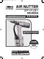
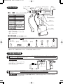
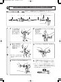
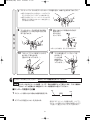
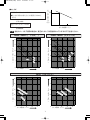
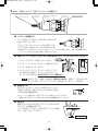
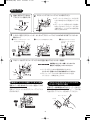
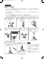
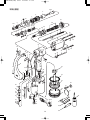
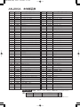
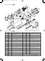
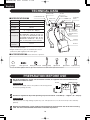
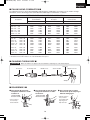
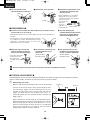
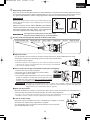
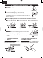
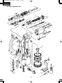
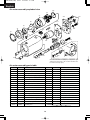
*AN-200A(J/GB) 05.3.1 2:28 PM ページ1
R
AIR NUTTER
エアーナッター
AN-200A
INSTRUCTION MANUAL
取扱説明書
FOR PROFESSIONALS
本機はプロ用エビナット専用工具です
日本語版
JAPANESE VERSION
英語版
ENGLISH VERSION
株式会社 ロブテックス
*AN-200A(J/GB) 05.3.1 2:28 PM ページ2
*AN-200A(J/GB) 05.3.1 2:28 PM ページ1
はじめに
このたびは、エビ印エアーナッターをお買い上げいただき、誠にありがとうございます。
ご使用に際し本説明書を必ずよくお読みいただき、正しくご使用ください。
お読みになった後も大切に保管してください。
本説明書は日本語版(国内販売仕様用)と英語版(海外輸出仕様用)に別れております。
一部、文章表現や付属部品が違いますがご了承ください。
目
次
SAN-200A取扱説明書(日本語版) .....................................................................P2 〜 P15
安全上のご注意 .......................................... 2
故障かな?と思ったら .............................11
各部の名称 .................................................. 4
ANー200A分解図 ..................................12
ご使用前の準備 .......................................... 4
ANー200A部品表 ..................................13
使用方法...................................................... 9
モーターアッシー分解図・部品表..........14
保守点検 ....................................................10
ノーズピーススペーサー〔別売〕
保管の仕方 ................................................11
の使用(オプション) ............15
エビナットについて(参考)....................15
SAN-200A取扱説明書(英語版) .....................................................................P16 〜 P29
INTRODUCTION
Thank you very much for purchasing “LOBSTER” Air Nutter. To ensure correct operation,
please read this instruction manual carefully before use, and keep it in a safe place for later
reference.
CONTENTS
SAN-200A Instruction Manual (Japanese version) ...............................................2 - 15
IMPORTANT SAFETY INSTRUCTIONS ... 16
MAINTENANCE......................................... 23
TECHNICAL DATA ..................................... 18
STORAGE.................................................. 24
PREPARATION BEFORE USE.................. 18
TROUBLESHOOTING ............................... 24
PULLING HEAD COMBINATION ................ 19
OPTION (the nosepiece spacer)................ 25
CHANGING THREAD SIZE......................... 19
AN-200A EXPLODED VIEW.......................26
DISASSEMBLY............................................ 19
REASSEMBLY............................................. 20
AN-200A PARTS TABLE .............................27
STROKE ADJUSTMENT ............................. 20
AIR MOTOR ASSEMBLY EXPLODED VIEW ....28
OPERATING THE AIR NUTTER ............... 22
AIR MOTOR ASSEMBLY PARTS TABLE....28
1
*AN-200A(J/GB) 05.3.1 2:28 PM ページ2
日 本 語 版 JAPANESE VERSION
安全上のご注意
◆ご使用前に、この「安全上のご注意」すべてをよくお読みのうえ十分理解されて正しくご
使用ください。
◆ここに示した注意事項は t警告 と t注意 に区分していますが、それぞれの意味は下記
の通りです。
t警告 :誤った取扱いをした場合、使用者が死亡または重傷を負う可能性が想定
される内容のご注意
t注意 :誤った取扱いをした場合、使用者が傷害を負う可能性が想定される場合、
及び物的傷害のみの発生が想定される内容のご注意
なお、 t注意 に記載した事項でも状況によっては重大な結果に結び付く可能性が
あります。いずれも安全に関する重要な内容を記載していますので必ず守ってくだ
さい。
◆お読みになった後は、お使いになる方がいつでも見られる所に必ず保管してください。
t警告
1. 使用空気圧は、0.59〜0.69MPa(6〜7kgf/cm2)を守ってください。
¡使用空気圧を超えて使用しますと、本機が破損して傷害や損傷を及ぼす恐れがあります。
2. シリンダー部から油圧オイルを給油する際は、給油後必ず油止めネジをゆるめて、
余分な油圧オイルを抜いてください。
¡余分な油圧オイルが入ることにより、本機が破損して傷害を及ぼす恐れがあります。
3. 本機とエアー源との接続は確実に行なってください。
¡ジョイントのネジが合わなかったり、ネジの入りしろが不十分であった場合、使用中にエアーホ
ースがはずれてけがをする恐れがあります。
4. 本機をエアー源からはずす時は、エアーの供給を止めてください。
¡圧縮空気によりエアーホースが跳ねたりして、けがをする恐れがあります。
5. ご使用前に、各部のネジが確実に締まっていることを確認してください。
¡締め付けが不十分ですと使用中にはずれるなどして事故やけがの原因となります。
6. ご使用前に、各部の損傷がないかをチェックし、損傷がある場合は、使用せずに修理に出
してください。
¡損傷がありながら使用しますとけがをする恐れがあります。
2
*AN-200A(J/GB) 05.3.1 2:28 PM ページ3
t注意
1. 本機のお手入れ、部品交換等の分解時には必ずエアーの供給を止めてください。
¡エアーが供給された状態で手入れや分解を行ないますとけがの恐れがあります。
2. ストローク調整は確実に行なってください。
¡ストロークが短すぎるとカシメ不足になり、エビナットが抜ける恐れがあります。
¡ストロークが長すぎるとエビナットのネジ山破損を起こし、ネジ強度が落ちます。
なお、この取扱説明書についているカシメしろ表はエビナットのみ適用可能です。他社品の場合は
適合いたしませんのでご注意ください。
3. コネクターをはずした状態で本機を操作しないでください。
¡指などを挟む恐れがあります。
4. 排気孔からの排気にご注意ください。
¡排気孔から勢いよく霧状のエアーが出る場合がありますので、目などを近づけないでください。
¡排気孔から勢いよく霧状のエアーが出る場合がありますので、衣服品物等が汚れる恐れがあり
ます。
5. 高所作業の際はご自身に安全ベルトをして、本機やナットの落下にも注意してください。
¡これらを怠りますと事故やけがの恐れがあります。
6. 油圧オイル、潤滑オイル、グリス等の油類はできるだけ皮膚などに触れないようにして
ください。
¡皮膚などに炎症をひき起こす場合がありますので、触れた場合は身体から完全に洗い落としてく
ださい。
7. 整理、整頓、清掃された場所でお使いください。
¡散らかった場所での作業は事故の恐れがあります。
8. 無理な姿勢で作業しないでください。
¡転倒等、けがの恐れがあります。
9. 作業者以外、作業場へ近づけないでください。
¡事故やけがの恐れがあります。
10. 本機の手入れは注意深く行なってください。
¡付属品の交換や部品交換は取扱説明書に従ってください。けがの恐れがあります。
¡握り部は常に乾いたきれいな状態に保ち、油やグリスがつかないようにしてください。けがの恐
れがあります。
11. 油断しないで十分注意して作業を行なってください。
¡本機を使用する場合は取扱方法、作業方法、周囲の状況等十分注意して慎重に作業してください。
軽率な行動をとると、事故やけがの恐れがあります。
¡常識を働かせてください。非常識な行動をとると、事故やけがの恐れがあります。
¡疲れている場合は使用しないでください。事故やけがの恐れがあります。
12. 本機の修理は当社にお申し付けください。
¡修理は必ずお買い求めの販売店、または当社にお出しください。修理の知識や技術のない方が
修理しますと、十分な性能を発揮しないだけでなく、事故やけがの恐れがあります。
13. 本機の改造をしないでください。
¡異常動作等事故やけがの恐れがあります。
14. モーターアッシー部のトラスネジ(A30)は触らないでください。
¡このトラスネジは組立時に調整してあります。触ると調整がずれて使用できなくなる恐れが
あります。
3
*AN-200A(J/GB) 05.3.1 2:28 PM ページ4
各部の名称
■仕
様■
ノーズピースM6
セットナット フロントフランジ
コネクター
排気孔
油止めネジ
プラグ
スクリューマンドレルM6
品
番
AN-200A
重
量
2.6kg
高
さ
290mm
全
長
262mm
使用空気圧
0.59〜0.69MPa
(6〜7kgf/cm2)
使用可能ナット
M3 M4 M5
M6 M8 M10
1ナット当りの
空 気 使 用 量
5R/nut
モーターアッシー
逆転レバー
トリガー
エアー供給口
※商品の仕様、デザインは予告なく変更
することがあります。
※重量、寸法は標準値ですので多少の数
値の上下があります。
■付属部品■
ご購入時に御確認ください。
ノーズピース
M4 M5
M8 M10
ハンガー
スクリューマンドレル
各1個
M4 M5
M8 M10
ホースジョイント1/4
各1個
袋ナット1/4
給油器
スパナA
スパナB
油圧オイル
※M3をご使用の際は、別売のノーズピースM3・スクリューマンドレルM3が必要です。
※輸出品は一部、付属部品が異なりますので、英文版の該当頁 を参照してください。
ご使用前の準備
1
コンプレッサーを用意し、エアーナッターとの間に必ずエアーフィルタ、レギュレータ、エアー
ルブリケーターを取り付けてください。
エアールブリケーター
エアーフィルタ
ご注意ください
これらが付いていないと、エアー内
の水分等により、円滑に作動しなく
なることがあります。
レギュレータ
2
レギュレータにより、使用空気圧を0.59〜0.69MPa(6〜7kgf/cm2)の範囲に調整して
ください。
ご注意ください
空気圧が高すぎると各部の損傷をまねき、低すぎると完全にエビナットがかしまらない
場合があります。
4
*AN-200A(J/GB) 05.3.1 2:28 PM ページ5
3
ご使用のエビナットのサイズに合わせて部品(スクリューマンドレル・ノーズピース)を交換して
ください。ご購入時にはM6用が装着されています。
■サイズ交換の方法■
注 意 必ずエアーの供給を止めてから作業を行なってください。
回り止めリング
ノーズピース
フロントフランジ部
マンドレルケース
スクリューマンドレル
回り止め固定ナット
アダプターナット
1
スパナBを使って
ノーズピースを
右に回してゆる
める。(逆ネジに
なっています。)
2
3
細いピン等を用い
て回り止めリング
を持ち上げセット
を解除する。
4
マンドレルケースを左に回してゆるめる。
6
ご使用になるサイズのスクリューマンド
レル、ノーズピースを用意してください。
分
解
スパナBを使ってフロントフランジ部を
右に回して
取りはずす。
(逆ネジに
なっています。)
※回り止めリングは完全には
ずさない方が組み込む際に
楽です。
5
スクリューマンドレルを取り出す。
※スクリューマンドレルを組み込む時に、マンド
レルケースと接触する部分(斜線部)に必ずグリ
スを塗ってください。グリスをお持ちでない場
合は付属の油圧オイルを着けてください。
グリス
スクリューマンドレル
5
*AN-200A(J/GB) 05.3.1 2:28 PM ページ6
7
スクリューマンドレルをマンドレルケースに組み込み、本体に止まるまでねじこむ。
※組み込む前に回り止め固定ナットの切り込み
が上になるようにしておくと 作業が楽です。
※組み込む際にスクリューマンドレルにエビ印
潤滑オイル(別売)またはマシン油を塗るとさ
らに寿命がのびます。
8
取
マンドレルケースの切り込みが回り
止め固定ナットの切り込みと合う所
まで左にもどす。
9
回り止めリングを取付ける向きに
気をつけて
切り込みに
セットする。
り
付
け
※長い方が先端側、短い方が本体側です。
10
4
フロントフランジ部をスパナBで
左に回して取り付ける。
(逆ネジになっています。)
11
スパナBを使ってノーズピースを
左に回して
しっかり締
め付ける。
(逆ネジにな
っています。)
適正なかしめ作業を行なうために、必ずストローク調整を行なってください。
要 点 ストロークはエビナットの材質、サイズ、母材の板厚によって変化します。この3要素の
どれか1つでも変更される場合はストローク調整をやり直してください。
■ストローク調整の方法■
母材
板厚
1 エビナットを取り付ける母材の板厚を測定する。
2 グラフから「適正かしめしろ」を求める。
使用するエビナットの品番(材質、サイズ)、
エビナットを取り付ける母材の板厚からグラ
フを使って適正かしめしろ(r)を求めます。
6
*AN-200A(J/GB) 05.3.1 2:28 PM ページ7
■たとえば
ナ
ッ 3.5
ト
か
し
め
し
ろ
●使用するエビナット:NSK-6M
●取り付ける母材の厚さ(かしめ板厚)が1.0mmと
すると
グラフより
(r)
適正かしめしろ(r)=3.5mm
1
2
かしめ板厚 (t)
となります。
注 意 他社のナットをご使用の場合は、適正かしめしろが各社異なっていますのでご注意ください。
NSK・NSD(スティール)
NAK・NAD( アルミ )
5
5
4
4
ナ
ッ
ト 3
か
し
め
し 2
ろ
︵
ナ
ッ
ト 3
か
し
め
し 2
ろ
︵
8M
4M
r
mm
6M
1
0
1
2
かしめ板厚(tmm)
3
M
mm
8M
6M
4M
5M
3M
r
5M
︶
10
1
︶
0
4
1
2
かしめ板厚(tmm)
3
4
NTK(ステンレス)
5
5
4
4
K-
6M
、8
M
NT
K5M
、1
0
ナ
ッ
ト 3
か
し
め
し 2
ろ
︵
M
-4
TK
NT
K6
N
TK
NT
5M
K4
M-3
20
0
M
-4
0
r1
M
r1
mm
NT
N
ナ
ッ
ト 3
か
し
め
し 2
ろ
︵
mm
︶
︶
0
1
2
かしめ板厚(tmm)
3
4
0
7
1
2
かしめ板厚(tmm)
3
4
*AN-200A(J/GB) 05.3.1 2:29 PM ページ8
3 求めた
適正かしめしろ
ノーズピース
安全カバー コネクター
セットナット
フロントフランジ
0.6
0.7
0.8
0.9
スクリューマンドレル
を使ってストロークを調整する。
q ストロークを調整する。
C
0.7
0.8
0.9
スパナBを使ってコネクターを右に回してゆるめる。
(逆ネジになっています。)
0.6
フロントフランジとセットナットのすき間 「C」を
グラフで求めた「適正かしめしろ」の値に合わせる。
※ご購入時「C」は1mmにセットされています。セットナットを1回転させると1mm寸法が増減します。
セットナットに貼られた目盛りを使って合わせてください。
w 実際にエビナットを使って「空かしめ」
(母材を使わずにエビナットだけをかしめる)を行なう。
1. エビナットをプライヤ等でしっかりつかむ。
2. スクリューマンドレルにエビナットを軽くあてがう。
3. ナッター本体のトリガーを引く。
r
引
き
続
け
る
4. エビナットにスクリューマンドレルが入っていき、
かしめ終わると逆転してエビナットからスクリュー
マンドレルがはずれる。はずれるまでトリガーは離さない。
空かしめ
注 意 途中でトリガーを離した場合は「二度引き」をせずに、逆転レバーを引きながら
トリガーを引いてスクリューマンドレルをはずしてください。
(P9参照)
e 微調整をする。
空かしめしたエビナットとかしめる前のエビナットの
寸法差(r)を計り、適正かしめしろとの差が±0.3mm
以上ある時は再度調整する。
r
※セットナットの目盛りは、適正ストロークとほぼ等しくなっていますが、
諸条件により若干のバラツキがありますので必ず微調整を行なってください。
r 固定する。
再度
「空かしめ」
を行ない適正ストローク
(±0.3mm以内)
になっていれば調整は終了です。
スパナBを使ってコネクターを左に回してしっかり固定
する。(逆ネジになっています。)
適正ストローク
8
*AN-200A(J/GB) 05.3.1 2:29 PM ページ9
使用方法
1
母材に適正な下穴をあけ
てエビナットを挿入する。
2
エビナットにスクリューマンドレルをあてがう。
※エアーナッターはエビナットに強く押
し付けずに軽くあてる程度にしてくだ
さい。
挿入
※エアーナッターは母材に対して直角に
なるようにあててください。かたむけ
て使用すると、かしまらずに逆転が始
まることがあります。
3
トリガーを引く(エビナットが、かしまってスクリューマンドレルがはずれるまでトリガーは
離さない。)
q
エビナットにスクリューマン
ドレルが入って行く
w
逆転してエビナットから
スクリューマンドレルが
抜ける。
逆転
正転
引き続ける
4
e
エビナットが母材にかしまる。
引き続ける
引き続ける
エビナットからスクリューマンドレルが完全に抜けてからトリガーを離す。
ご注意ください
作業途中でトリガーを離してしまっても
絶対に「二度引き」しないでください。
※トリガーを引いたままの連続作業はできません。
トリガーを一旦離してから次の作業に移ってください。
注油
離
す
※スクリューマンドレルのネジ部にはひんぱんに注油
してください。作業性が向上します。
作業途中でトリガーを離してしまった場合
エビナットにスクリューマンドレルが
引っ付いて取れない場合
逆転レバーを引きながらトリガーを引いてくだ
さい。
逆転してエビナットからスクリューマンドレル
がはずれます。
必ずエアーの供給を止めてからモーターの後ろの
プラグをはずし、マイナスのドライバーで中の軸
を左に回してエビナットをはずしてください。
逆転レバーを引きながら
エアーモーター
プラグ
逆転
トリガーを引く
9
*AN-200A(J/GB) 05.3.1 2:29 PM ページ10
保守点検
■油圧オイルの給油■
エアーナッターを長時間使用されますと油圧オイルが減少してエビナットがかしまらなかったり、
エビナットは、かしまっても逆転しないなどの症状が起こります。これは油圧オイルの減少により、
かしめしろが変わってしまうためです。
月に一回程度は下記の[1]の手順で給油を行なってください。一ヶ月以内の細かな給油には[2]の
給油方法がお手軽です。
[1]シリンダー部からの給油(シリンダーのグリスアップも兼ねています)
エアーナッターを長期間使用されますとエアーシリンダー内にほこりや、磨耗くず等がたまり円滑性、
耐久性に悪影響をおよぼします。月に一回の給油の際この方法で手入れも行なってください。
q エアーの供給を止める。
スパナAを使ってシリンダー
キャップをはずす。
w シリンダーを垂直に立てて、
プライヤ等を使ってエアー
ピストンを引き抜く。
r フレームの注油孔から油圧オイルを
補給し、エアーピストンを取り付け
る。
t スパナAを使ってシ
リンダーキャップを
取り付ける。
e シリンダー内面にグリスを
塗る。
y 取付け後、油止めネジを
ゆるめて、余分なオイル
を抜く。
油止めネジを締め付ける。
油圧オイルの適正量
ここまで油圧オイルを入れる
シリンダー
オ
イ
ル
フレーム
[2]油止めネジ部からの給油
q エアーの供給を止める。油止め
ネジをはずして、この部分にあ
らかじめ油圧オイルを入れた給
油器を取り付ける。
w 給油器のピストンが
重く感じるまで押し
込む。
要点
¡給油器をご使用後、そのまま放置
すると ピストンの先端部のゴム
が劣化して使え なくなる場合が
あります。
¡給油器からピストンを抜き取り、
ゴムに付いた油分を拭き取ってく
ださい。
e 油止めネジを締め付
ける。
10
¡給油器からピストンを抜いた状態
で保管してください。
*AN-200A(J/GB) 05.3.1 2:29 PM ページ11
■スプール部への注油■
スプールに油分が無くなると動作不良を
起こします。時々、シリンダーの排気孔
から市販のスプレー式潤滑剤等で注油し
てください。
シリンダー排気孔
スプレー式潤滑剤
保管の仕方
¡ほこりや湿気の少ない、風通しの良い、落下の恐れの無い場所で保管してください。
¡長時間使用しない時は保守点検を行った後、保管してください。
¡本機をより長くご使用いただくために、定期的なオーバーホール
(有償)
を当社にご依頼ください。
オーバーホール及び修理はお買い上げの販売店、またはお近くの当社営業所までお問い合わせく
ださい。
お問い合わせ・修理依頼の際は、以下の項目を確認していただき使用機種名・使用状況・症状等
できるだけ詳しくご連絡くださいますと、納期(修理上がり)を短縮することにもなりますので宜
しくお願い致します。
故障かな?と思ったら
故障と、お考えの前に以下の項目のチェックを行なってください。
すべてチェックしてもあてはまらない場合は当社にお問い合わせ、または修理を依頼してください。
症
状
原
因
処
置
スクリューマンドレル
が回転しない。
¡エアーモーターの性格上、モーター
が中立の位置にある場合、回転しな
いことがあります。
¡逆転レバーを引いたままトリガーを
引くか、スクリューマンドレルを手
で左右に回してみる。
スクリューマンドレル
が正転するが、エビナ
ットを取り込まない。
¡スクリューマンドレルのサイズがエ
ビナットと合っていない。
¡スクリューマンドレルのネジが損傷
している。
¡サイズに合ったスクリューマンドレ
ルに交換してください。
¡新しいスクリューマンドレルに交換
してください。
スクリューマンドレル
が正転しエビナットを
取り込むが、かしまら
ずに逆転してしまう。
¡スクリューマンドレルの先端が障害
¡接触しなくなるまでスクリューマン
物と接触する。
(パイプへの取付けで、
ドレルの先端を削るか、ノーズピー
スクリューマンドレルの先端がパイ
スの下に別売のノーズピーススペー
プの底に当たる。シールドナットの
サーを付けて下さい。(P15参照)
使用で、スクリューマンドレルの先
端がナットの底に当たるなど。)
スクリューマンドレル
が正転しエビナットを
取り込んで下がるが逆
転せず下がったまま。
¡油圧オイルが減少している。
¡ストローク調整が間違っている。
(適正かしめしろよりもプラスめにセ
ットしている。)
¡油圧オイルを補充してください。
¡再度、正しくストローク調整を行な
ってください。
スクリューマンドレル
が最初から下がり逆転
したまま。
¡シリンダー部スプールのOリングが
へたっている。
¡Oリングを交換してください。
¡シリンダー排気孔から注油してくだ
さい。
使用油圧オイル
油圧オイルの粘性は、本機の性能に影響を与えますので、必ずエビ印純正の油圧オイルをご使用く
ださい。
11
*AN-200A(J/GB) 05.3.1 2:29 PM ページ12
10-D
本体分解図
9
8
7
4
6
27
5
3
2
26
1-D
18
18 19
17
14
23
25
24
31
13
11
12
30
75
74
28
16
15
73
29
75
74
20
72
35
75
74
34
72
64
32
67
21
33
22
68
71
72
39
65
63
63
36
37
36
66
67
72
38
40
41
69
92
70
62
91
53
42
61
55
93
60
59
58
43
54
51
52
57
56
56
96
44
49
50
45
4646
47
48
95
51
52
94
12
97
*AN-200A(J/GB) 05.3.1 2:29 PM ページ13
AN-200A
本体部品表
図No
部品コードNo
部
品
名
*1-A* *15445* *ノーズピース M3*
1-B
15464
ノーズピース M4
1-C
15480
ノーズピース M5
1-D
15618
ノーズピース M6
1-E
15640
ノーズピース M8
1-F
15661
ノーズピース M10
2
12898
ノーズ
3
12899
安全カバー
4
12901
六角穴付ボルト M4
5
15667
バネ座金 M4B
6
17112
コネクター
7
17108
セットナット
8
17104
フロントフランジ
9
15692
マンドレルケース
*10-A* *15460* *スクリューマンドレル M3*
10-B
15476
スクリューマンドレル M4
10-C
15617
スクリューマンドレル M5
10-D
15635
スクリューマンドレル M6
10-E
15656
スクリューマンドレル M8
10-F
15676
スクリューマンドレル M10
11
17100
回り止めリング
12
17096
アダプターナット
13
17092
回り止め固定ナット
14
15955
ガイド
15
15680
切替調整ネジ
16
15732
切替調整ナット
17
15841
ガイドスプリング
18
10128
Oリング P-12
19
10129
Bリング P-12
20
15837
フレーム(18、19、36、37付)
21
12120
Oリング P-5
22
12135
油止めネジ
23
17077
オイルピストン
24
12437
Oリング P-26
25
12438
Bリング P-26
26
16623
リターニングスプリング(U)
27
17088
フレームキャップ
28
15817
伝達棒
29
16101
スプリングピン φ1.2
30
14642
平座金 M5
31
10133
ジョープッシャースプリング
32
15744
逆転レバー
33
14642
平座金 M5
34
15768
ガイドピン
35
15800
E型止め輪 E-3.2
36
10337
Oリング P-10A
37
16030
Bリング P-10A
38
15869
シリンダー
*
*の部品はオプション
図No
39
40
41
42
43
44
45
46
47
48
49
50
51
52
53
54
55
56
57
58
59
60
61
62
63
64
65
66
67
68
69
70
71
72
73
74
75
部品コードNo
10112
10134
14798
10080
15276
10151
42479
10149
42501
10285
14239
14255
14475
14294
14848
10454
14172
12120
10149
14513
14818
10149
14767
14848
15611
14375
10202
10282
10147
10251
10145
14154
29151
15645
29150
15435
15667
91
92
93
94
95
96
97
10140
10139
15468
10141
14036
10012
14142
部
品
名
フレームロックナット
Oリング P-60
エアーピストン(U)
Oリング G-70
シリンダーキャップ
Oリング S-10
ニップル
Oリング P-7
ロータリージョイント
E型止め輪 E-7
ウレタンボール
バルブスプリング
Oリング S-8
ホルダー
ワンタッチジョイント
Oリング P-4
バルブプッシャー
Oリング P-5
Oリング P-7
スプール(1)
パッキン
Oリング P-7
パイロットホルダー
ワンタッチジョイント
ウレタンチューブ
トリガー
連結棒
レバー
スプリングピン 3×6
スプリングピン 3×20
スプリングピン 3×18
溝付ピン
グリップカバー
皿ネジ M3
モーターアッシー
六角穴付ボルト M4×90
バネ座金 M4B
ホースジョイント1/4
袋ナット1/4
ハンガー
スパナ A
スパナ B
エビ印油圧オイル
給油器
*別売* *889* *エビ印潤滑オイル*
*別売* *28054* *ノーズピーススペーサー*
部品の注文方法 機種名、部品コードNo.、部品名、数量を明記してご注文ください。
(例)
機種名
部品コードNo.
部品名
数量
AN-200A
15617
スクリューマンドレルM5
2
※部品が改良された場合、旧部品の在庫は5年間となっておりますのでご了承ください。
13
*AN-200A(J/GB) 05.3.1 2:29 PM ページ14
モーターアッシー分解図
A10
A9
A7
A18
A20
A21
A19
A6
A17
A5
A16
A2
A8
A1
A22
A14
A35
A3
A13
A27
A4
A29
A15
A28
A12
A26
A34
A33
A32
A36
A24
A25
A11
※トラスネジ(A30)は組立時に調整してありますので、
触らないでください。
モーターアッシー部品表
部品コードNo
部
A1
17068
穴用止め輪
A2
28468
A37
A30
A23
図No
A31
品
名
図No
部品コードNo
A20
16665
プラグ
アダプターキャップ
A21
16863
六角ボルト(4×10)
34
部
品
名
A3
11932
スプリングピン
A22
15667
ばね座金(M4B)
A4
28483
クラッチリターニングスプリング
A23
16867
切換ピン
A5
16452
ベアリング
629zz
A24
16871
スプール(2)
A6
16136
ギヤーフレーム
A25
10149
Oリング P−7
A7
28469
インターナルギヤー
A26
16875
アタッチメント
A8
14438
スプリングピン
A27
10219
Oリング P−9
A9
16733
プラネットギヤー
A28
28474
スプールストッパー
A10
16829
ギヤーフレーム(1)
A29
16826
スプールリターンスプリング
A11
14848
ワンタッチジョイント
A30
28475
トラスネジ
A12
44952
モーターケーシング
A31
10220
Oリング S−6
A13
29060
セットスクリュー
A32
28481
プランジャースプリング
A14
16847
マフラ
A33
28484
ウレタンボール
A15
16851
モーターセット(A16付)
A34
43580
プランジャーケース
A16
14015
ベーン
A35
43581
カム
A17
16855
シールパッキン
A36
14475
Oリング S−8
A18
44953
キャップ
A37
44954
シムワッシャ
A19
10219
Oリング P−9
φ2×8
φ2×10
14
5/32
*AN-200A(J/GB) 05.3.1 2:29 PM ページ15
オプション
ノーズピーススペーサー(別売)の使用
以下のような理由でかしめ作業ができない場合は別売のノーズピーススペーサーが役立ちます。
(ノーズピーススペーサーは必ずノーズとノーズピースの間に入れてノーズピースをしっかり
締め付けて使用してください。)
角パイプの底に、スクリューマンドレル
の先端が当たって正常なかしめ作業がで
きない。
例1
角パイプ
参
考
例2
シールドナットの奥にスクリューマンド
レルの先端が当たって正常なかしめ作業
ができない。
ノーズピース
スペーサー
ノーズピース
スペーサー
4mm
4mm
シールド
ナット
エビナットについて
Dタイプ
Kタイプ
¡本機には必ずエビナットをご使用ください。
¡他社のナットをご使用になった場合、適正かしめしろが
各社異なっていますのでP7のグラフはあてはまりません。
ご注意ください。
材質:スティール
Kタイプ(NSK)
品 番
外部寸法(mm)
D d
L
d
品 番
T
適用 適正かしめ 下穴径
厚
外部寸法(mm) ネジ 板
D d T
(mm)
(φmm)
M3×0.5
0.5〜2.0
5.1
L
NSK3M
5
6 8.5
NSK4M
6
7 11.3 NSD4M
6
9 0.8 11.0 M4×0.7
0.5〜2.0
6.0
NSK5M
7
8 12.7 NSD5M
7
10 1.0 12.6 M5×0.8
0.5〜3.2
7.1
NSK6M
9
10 15.4 NSD6M
9
12 1.5 16.0 M6×1.0
0.5〜3.2
9.1
NSK8M
11 12 16.5 NSD8M 11 14 1.5 16.7 M8×1.25
0.5〜3.2
11.1
0.5〜4.0
13.1
NSK10M 13 14 17.8
M10×1.5
L
材質:アルミニウム
品 番
外部寸法(mm)
D d
L
品 番
適用 適正かしめ 下穴径
厚
外部寸法(mm) ネジ 板
D d T
L
(mm)
(φmm)
D
材質:ステンレス
Kタイプ(NTK)
適用 適正かしめ 下穴径
厚
外部寸法(mm) ネジ 板
(mm)
(φmm)
9.5 M4×0.7
0.3〜1.0
6.1
NTK4M-20 6
7 10.6 M4×0.7
1.0〜2.0
6.1
7
8 11.1 M5×0.8
0.3〜1.5
7.1
NTK5M-30 7
8 12.1 M5×0.8
1.5〜3.0
7.1
NTK4M
Dタイプ(NAD)
L
D
品 番
Kタイプ(NAK)
d
Dタイプ(NSD)
NTK5M
D d
L
6
7
NAK4M 6
7 11.3 NAD4M 6
9 0.8 11.0 M4×0.7
0.5〜2.0
6.1
NTK6M
9
10 14.1 M6×1.0
0.3〜2.0
9.1
NAK5M 7
8 12.7 NAD5M 7
10 1.0 12.6 M5×0.8
0.5〜3.2
7.1
NTK6M-40 9
10 15.6 M6×1.0
2.0〜4.0
9.1
NAK6M 9
10 14.6 NAD6M 9
12 1.5 16.0 M6×1.0
0.5〜3.2
9.1
NTK8M
11 12 15.0 M8×1.25
0.3〜2.0
11.1
0.5〜3.2
11.1
NTK10M 13 14 15.7 M10×1.5
0.3〜2.0
13.1
NAK8M 11 12 15.7 NAD8M 11 14 1.5 16.7 M8×1.25
15
*AN-200A(J/GB) 05.3.1 2:29 PM ページ16
ENGLISH VERSION
IMPORTANT SAFETY INSTRUCTIONS
◆ Be sure to read the following Important Safety Instructions carefully and make sure that you
understand them thoroughly before using this tool.
◆ This is the safety alert symbol. It is used to alert you to potential personal injury hazards.
Obey all safety messages that follow this symbol to avoid possible injury or death.
◆ The Important Safety Instructions are divided into tWARNING and tCAUTION .
The differences between these two levels are described below.
tWARNING : Indicates a potentially hazardous situation which, if not avoided, could result in
death or serious injury to the operator.
tCAUTION : Indicates a potentially hazardous situation which, if not avoided, may result in
moderate injury to the operator or physical damage.
Moreover, failure to follow the instructions marked with the tCAUTION symbol or cautions without
a tCAUTION symbol which appear in the text of this manual may also have serious results in
some cases. Always be sure to observe the instructions given in the Important Safety Instructions.
S After reading this manual, keep it in a safe place where it is easily accessible to tool users.
tWARNING
1. The air pressure should be kept within the range of 0.59 to 0.69 MPa (6 to 7 kgf/cm2, 85 to 100 psi).
• If an air pressure which is greater than this is used, the tool may become damaged, and injury or damage
to property may result.
2. When adding hydraulic oil through the air cylinder, be sure to loosen the bleed plug afterwards to
allow any excess hydraulic oil to drain away.
• If excess oil is allowed to remain inside the tool, damage to the tool or personal injury may result.
3. Make sure that the tool and the air source are connected securely.
• If the threads of the joints do not match or if the screws are not inserted far enough, the air hose may
become disconnected during use and injury may result.
4. Turn off the air supply before disconnecting the tool from the air source.
• Compressed air may cause the air hose to whip around, and injury may result.
5. Check that all screws are securely fastened before using the tool.
• If any of the screws are not sufficiently tightened, they may fall out during use and accidents or injury may
result.
6. Check that the tool parts are free from damage before use. Any damaged parts should be repaired
before the tool is used.
• If the tool is used while any parts are still damaged, injury may result.
16
*AN-200A(J/GB) 05.3.1 2:29 PM ページ17
English
tCAUTION
1. Always turn off the air supply before disassembling the tool for cleaning and maintenance
purposes.
• If the tool is cleaned or disassembled with the air supply connected, injury may result.
2. Adjust the pulling stroke correctly.
• If the stroke is too short, the rivet nut may not be pulled up sufficiently, effecting its clamping ability.
• If the stroke is too long, the threads of the rivet nut may strip effecting the strength of the fastener.
Moreover, the pull-up specification table in this instruction manual is only applicable to “Lobster” brand
rivet nuts. Rivet nuts from other manufacturers may not comply with these specifications.
3. Do not operate the air nutter while the connector is disconnected.
• Items such as fingers may become caught in the mechanism.
4. Avoid direct contact with air coming out of the air outlet holes.
• Pressurized air containing fine particles is discharged from the air outlet holes during use. Keep eyes away
from this area.
• Pressurized air containing fine particles is discharged from the air outlet holes during use. This may soil
clothing or other items.
5. If using in elevated locations, use a safety harness, and take care to avoid dropping rivet nuts or the
tool itself.
• Damage or injury may result if this practice is not followed.
6. Avoid skin contact with substances such as hydraulic oil, lubricating oil and grease.
• Such substances may cause inflammation of the skin. If they come into contact with your skin, wash the
affected area thoroughly.
7. Make sure that the workplace is safe, clean and organized.
• Accidents can easily occur in untidy workplaces.
8. Avoid uncomfortable postures while working.
• You may fall down and injury may result.
9. Keep people who are not involved in work away from the workplace.
• Accidents or injury may result.
10. Maintain the tool with due care.
• Refer to the Instruction Manual for details on replacing parts and attachments, otherwise injury may occur.
• Keep the grip clean and dry at all times, and never let it become greasy, otherwise injury may occur
during use.
11. Use the tool carefully and concentrate on correct operation at all times.
• Use the tool with proper care, paying full attention to methods of handling and operation and surrounding
conditions. Accidents and injury may result if this practice is not followed.
• Use common sense at all times, otherwise accidents or injury may result.
• When you are tired, do not use the tool, otherwise accidents or injury may result.
12. Ask Lobtex to carry out any repair work required.
• Repair work should only be carried out by a qualified technician. Please contact your nearest “Lobster”
distributor, representative or direct to Lobtex Co.,Ltd.,Osaka. If the tool is repaired by someone without
the necessary qualifications and experience, the tool may not perform to optimum standards, and
accidents or injury may result.
13. Do not attempt to modify the tool.
• Unauthorized modifications may cause malfunctions which can lead to accidents or injury.
14. Do not turn the truss head screw (Index. No. A30)
• The truss head screw (Index. No. A30) is pre-adjusted to give optimal tool performance. Do not turn
otherwise the tool will not work properly.
17
*AN-200A(J/GB) 05.3.1 2:29 PM ページ18
English
TECHNICAL DATA
SET NUT
NOSEPIECE M6
Model No.
BLEED PLUG
CONNECTOR
AIR OUTLET
HOLES
AN–200A
Weight
2.6 kg
Height
290 mm
Total length
262 mm
Operating air
pressure
0.59 ~ 0.69 MPa
(6 ~ 7 kgf/cm2, 85 ~ 100 psi)
Work Capacity:
FRONT FLANGE
SCREW MANDREL M6
■ SPECIFICATIONS ■
MOTOR
CAP
AIR MOTOR
ASSEMBLY
ANY STANDARD THIN WALL RIVET
NUT FROM M3 – M10 (#6, #8, #10, 1/4,
5/16, 3/8) IN ALL MATERIALS AND ANY
FLANGED HEAD RIVET NUT IN ALL
MATERIALS FROM M3 – M8 (#6, #8,
#10, 1/4, 5/16) (M10 or 3/8 in aluminum)
Air consumption
per rivet nut
REVERSE SWITCH
LEVER
TRIGGER
5R/nut
AIR INLET
* Product specifications and design are subject to change for
improvement without notice.
* Weight and dimensions given are standard values. Actual
products may differ slightly from the values given.
■ ACCESSORIES ■
Hanger
Check at the time of purchase.
Hose joint 1/4
Hose joint nut 1/4
Priming pump
Spanner A
Spanner B
Hydraulic oil
* Accessories differ slightly from those given above between tools delivered in Japan and overseas.
PREPARATION BEFORE USE
1
Set up the compressor, and be sure to install an air filter, air regulator and lubricator between the
compressor and the air nutter.
Lubricator
Air filter
ATTENTION!
If these are not installed, water or other particles in the air may prevent
the tool from operating smoothly.
Air regulator
2
Use the air regulator to adjust the operating air pressure to 0.59 ~ 0.69 MPa (6 ~ 7 kgf/cm2, 85 ~ 100 psi).
ATTENTION!
If the air pressure is too high, damage to parts may occur. If the pressure is too low, the rivet nut may not be sufficiently
pulled up.
3
Replace the attachments (screw mandrel and nosepiece) to conform to the size of the rivet nut being
used. The tool is fitted with M6 attachments at the time of purchase.
18
*AN-200A(J/GB) 05.3.1 2:29 PM ページ19
English
■ PULLING HEAD COMBINATION ■
It is important to have a correct Screw Mandrel and Nosepiece combination. If incorrect or if you need to change
thread size, refer to the listing on the Screw Mandrel and Nosepiece combination, as follows:
SCREW MANDREL AND NOSEPIECE COMBINATION
(Pull-up Stud)
Screw Mandrel
Thread Size
(Anvil)
Nosepiece
Index
Code
010A
010B
010C
010D
010E
010F
15460
15476
15617
15635
15656
15676
Index
**Thread
Conversion Kit
Code
Index
Code
15445
15464
15480
15618
15640
15661
100A
100B
100C
100D
100E
100F
16830
16834
14700
16328
16537
16542
Metric Threads
M3 × 0.5 – 6H
M4 × 0.7 – 6H
M5 × 0.8 – 6H
*M6 × 1.0 – 6H
M8 × 1.25 – 6H
M10 × 1.5 – 6H
001A
001B
001C
001D
001E
001F
Unified Threads
#6 – 32
#8 – 32
#10 – 24
#1/4 – 20
#5/16 – 18
#3/8 – 16
UNC – 2B
UNC – 2B
UNC – 2B
UNC – 2B
UNC – 2B
UNC – 2B
010G
010H
010J
010K
010M
010N
16868
16864
16872
14327
15787
16588
001G
001H
001J
001K
001M
001N
16837
16841
16845
16849
16853
16857
100G
100H
100J
100K
100M
100N
16861
14299
14419
16152
16737
16840
#10 – 32
#1/4 – 28
#5/16 – 24
#3/8 – 24
UNF – 2B
UNF – 2B
UNF – 2B
UNF – 2B
010R
010S
010T
010U
14040
14600
16167
16821
001J
001K
001M
001N
16845
16849
16853
16857
100R
100S
100T
100U
15442
16329
16833
16844
* The tool is initially supplied with M6 thread attachment fitted.
** Thread Conversion Kit includes a set of Screw Mandrel & Nosepiece.
■ CHANGING THREAD SIZE ■
tCAUTION
Make sure that the air supply is disconnected before replacing any of the attached parts.
Stop ring
Nosepiece
Front flange unit
Mandrel case
Screw mandrel
Adaptor lock nut
Adaptor
■ DISASSEMBLY ■
q Use spanner B to turn the
nosepiece clockwise in order
to loosen it.
(A left-handed
thread is used.)
w Use spanner B to turn the front
flange unit clockwise in order
to loosen it.
(A left-handed
thread is used.)
* The nosepiece
moves freely
back and forth.
19
e Use a narrow pin or similar
device to lift up the stop ring in
order to disengage it.
* It will be easier to
carry out later
reassembly if the
stop ring is not
fully removed.
*AN-200A(J/GB) 05.3.1 2:29 PM ページ20
English
r Turn the mandrel case
counterclockwise to loosen it.
t Remove the screw mandrel.
y Prepare the replacement screw
mandrel and nosepiece with
the correct size.
* When installing the screw mandrel,
apply grease to the section which
contacts the mandrel case (shaded
area).If you do not
have any grease,
Grease
apply the
accessory
hydraulic oil or
Screw mandrel
similar lubricant.
■ REASSEMBLY ■
u Insert the screw mandrel into the mandrel case, and then screw it
into the tool as far as it will go.
* Working will be easier if the notch in the adaptor lock nut is facing upward before
assembly.
i Turn the mandrel case
counterclockwise until the notch
in the case is aligned with the
notch in the adaptor lock nut.
* The working life of the screw mandrel will be extended
if you apply some “Lobster” brand lubricating oil (sold
separately) or available machine oil to the screw
mandrel at the time of reassembly.
o Align the stop ring with the
notches, making sure that it
faces in the correct direction.
* The longer end should
be at the front, and
the shorter end
should be at the main
unit.
4
!0 Re-attach the front flange unit
counterclockwise using
spanner B.
(A left-handed
thread is used.)
!1 Use spanner B to turn the
nosepiece counterclockwise
until it is securely tightened.
(A left-handed
thread is used.)
Be sure to adjust the stroke to ensure that the rivet nuts are pulled up correctly.
■ STROKE ADJUSTMENT ■
The AN-200A tool, leaves the factory equipped with M6 (metric) Nose Assembly and is pre-adjusted to provide a
stroke of 1.0mm (.040”). To find out the actual tool stroke, proceed as follows:
q Determining tool stroke.
Measure and record overall length of the rivet nut, before upset.
Workpiece
Thickness
Connect the tool to the air line. Grasp shank end of the rivet
nut with fingers tightly to prevent turning. Point the tool
mandrel at right angle to the rivet nut head and pull the
trigger and hold until the tool completes the cycle i.e.,
unthreading itself from the upsetted fastener. Release the
trigger. (Fig. 1)
Again, measure the overall length of the upsetted fastener.
Record the difference between measurement of the fastener
before pull-up and after pull-up. This difference “L” is the
amount of actual stroke for which the tool is now adjusted.
(Fig. 2) This information is essential to the next step of
determining the amount of stroke required.
20
L
L=ACTUAL TOOL STROKE
Fig. 1
Fig. 2
*AN-200A(J/GB) 05.3.1 2:29 PM ページ21
English
w Determining stroke required
Each rivet nut will accommodate thickness of material between the minimum and maximum grip limits. Refer to
your fastener design guide for details and determine the correct stroke required to install the specific fastener
in a given material thickness. Stroke setting requirements from other rivet nut manufactures may vary.
ATTENTION!
=STROKE REQUIRED
Suppose the fastener used is “Lobster” NSK-6M, to be installed in
1.0mm material thickness. The stroke (pull-up) needed is 3.5mm, as
noted from the fastener data sheet, which is a close approximation
of the stroke required to attain a proper bulge. (Fig. 3 & 4)
ATTENTION!
TOOL STROKE
Excessive stroke (pull-up) may break screw mandrel (pull-up stud)
threads, strip fastener threads or both. Inadequate stroke may result in
loose installation.
5
4
NS
K6M
3
2
1
0
1
2
3
4
MATERIAL THICKNESS
If using fasteners made by other manufacturers, these
fasteners may have different pull-up stroke requirements.
UPSETTED FASTENER
Fig. 3
Fig. 4
e Use the actual pull-up length thus obtained to adjust the tool stroke
NOSEPIECE (M6)
SAFETY COVER CONNECTOR
SET NUT
FRONT FLANGE
0.6
0.7
0.8
0.9
SCREW MANDREL (M6)
q Adjust the stroke.
Use spanner B to turn the connector clockwise in order to loosen it. (A left-handed thread is used.)
0.9
C
0.6
* At the time of purchase, the clearance C is set to 1 mm. The clearance increases
or decreases by 1 mm for each full rotation of the set nut. Use the scale attached
to the set nut as a guide for setting.
0.7
0.8
Set the gap C between the front flange and the set nut to the same distance
as the actual stroke required.
w Set an actual rivet nut (pull it up without inserting into a workpiece).
1. Hold the rivet nut securely using pliers.
2. Place the rivet nut gently against the screw mandrel.
3. Pull the trigger on the air nutter.
4. The screw mandrel will thread into the rivet nut. Once the
pull-up is complete, the tool will reverse spin the screw
mandrel out of the rivet nut. Do not release the trigger
until the screw mandrel comes fully out of the rivet nut.
ATTENTION!
Pull
continuously
Upset rivet nut
If the trigger is released before the cycle is complete, do not attempt to repeat the cycle by pulling
the trigger again. Instead, pull the reverse switch lever and hold it in that position while pulling the
trigger to remove the screw mandrel. (Refer to page 20.)
e Make fine adjustments.
Measure the difference in length (R) between the upset rivet nut and an unused rivet nut. If this difference is
more than ±0.3 mm from the actual pull-up length, repeat the stroke adjustment.
* The scale on the set nut is almost equivalent to the actual stroke, but slight differences may occur
depending on various conditions. Thus fine adjustments should always be carried out.
r Lock the stroke setting.
Repeat the “upset” procedure once more. If the difference in length (R) is within
±0.3 mm of the required value, adjustment is complete.
Use spanner B to turn the connector counterclockwise to lock it securely.
(A left-handed thread is used.)
Actual stroke
21
*AN-200A(J/GB) 05.3.1 2:29 PM ページ22
English
OPERATING THE AIR NUTTER
1
Drill a hole of the appropriate size into the workpiece, and insert the rivet nut
into the hole.
2
Place the screw mandrel against the rivet nut.
Insert
* Place the tool gently against the rivet nut, without pushing too hard.
* Hold the tool so that it is at a right angle to the surface of the workpiece. If it is used at
an angle, it may start reversing without pulling up the rivet nut.
“additional information”
or partially thread the rivet nut on to the screw mandrel and insert the screw mandrel and
rivet nut into a prepared hole.
3
Pull the trigger. (Do not release the trigger until the rivet nut has been pulled up and the screw
mandrel has completely reversed out of the fastener.)
q The screw mandrel moves into
the rivet nut.
w The rivet nut is pulled up in the
workpiece.
Reverse
Forward
Keep pulling
4
e The screw mandrel reverses
and comes out of the rivet nut.
Keep pulling
Keep pulling
Once the screw mandrel has come completely out of the rivet nut,
release the trigger.
ATTENTION!
If you release the trigger before the operation has been completed,
do not attempt to press the trigger again.
* Continuous operation by keeping the trigger pressed is not possible.
Release the trigger and then press it again to pull up the next rivet nut.
* Periodically lubricate the threaded section of the screw mandrel. This will improve
workability.
If you release the trigger during
pulling-up
While pulling the reverse switch lever, pull the trigger.
The air nutter will switch to reverse and the screw
mandrel will come out of the rivet nut.
Lubricate
Release
If the screw mandrel sticks inside the rivet
nut and will not come out
First turn off the air supply. Then remove the motor cap
from the rear of the motor and use a flat-tipped screwdriver
to turn the internal conveyor rod counterclockwise until the
screw mandrel is free from the rivet nut.
While pulling the reverse switch lever
Air motor Assembly
Motor cap
Reverse
Pull the trigger
22
*AN-200A(J/GB) 05.3.1 2:29 PM ページ23
English
MAINTENANCE
■ ADDING HYDRAULIC OIL ■
When the air nutter is used for a long period of time, the amount of hydraulic oil decreases. This results in the rivet
nuts not being pulled up, or rivet nuts that are pulled up but the tool does not reverse and disengage. This happens
because of changes in the pull-up stroke resulting from a loss of hydraulic oil.
Add hydraulic oil by following procedure q at least once a month. If you wish to add oil more frequently than once
a month, procedure w is easier to follow.
q Adding hydraulic oil through the cylinder (includes cylinder greasing procedure)
When the tool has been used for a long period of time, dust and shavings will get inside it, reducing
smoothness of operation and adversely affecting the durability. Use this procedure when adding oil at a
frequency of once a month.
q Turn off the air supply.
Use spanner A to remove the
cylinder cap.
w Stand the cylinder up vertically,
and then use pliers or a similar
tool to pull out the air piston.
r Pour in the hydraulic oil through the oil
hole in the frame, and then install the
air piston.
t Use spanner A to
install the cylinder cap.
CORRECT OIL LEVEL
e Apply grease to the inside of
the cylinder.
y After installation, loosen the
bleed plug to drain any excess
oil.Then re-tighten
the bleed plug.
Fill with oil up to here
Cylinder
Oil
Frame
w Adding hydraulic oil through the bleed plug
q Turn off the air supply. Then remove the
bleed plug and insert the priming pump
containing the
necessary amount
of hydraulic oil.
w Gently press the piston of
the priming pump until
back pressure is felt.
e Remove the priming
pump, and re-tighten the
bleed plug.
Tip
• If the priming pump is not cleaned after use, the rubber at the end of piston will deteriorate and the priming pump will no longer
work properly.
• Remove the piston from the priming pump and wipe away any oil adhering to the rubber.
• Store the priming pump with the piston thus removed.
23
*AN-200A(J/GB) 05.3.1 2:29 PM ページ24
English
■ LUBRICATING THE SPOOL ■
A dry spool may hinder the air flow operation of the tool.
Periodically apply any available spray-type lubricant through the air
outlet hole in the cylinder.
Air outlet hole
Spray-type lubricant
STORAGE
• Store in a place which is well-ventilated and free from excessive dust and humidity, and where there is no danger
that the tool will fall.
• If not using the tool for an extended period of time, carry out a maintenance inspection before storing it away.
• To increase the working life of the tool, it is recommended that you give it periodic overhauls. Contact the place of
purchase or your nearest “Lobster” dealer for any overhauls and repair work required. (A charge will be made for
this service.)
* If making any enquiries about this product or requests for repair work, first check the troubleshooting items below, and make a
note of the model number, the usage conditions and the trouble symptoms in as much detail as possible. If you can provide this
kind of information, it will contribute to reduce the amount of time required for delivery or repairs to be completed.
TROUBLESHOOTING
If a problem occurs, check the following.
If the problem persists after checking the items in the table below, contact your nearest “Lobster” dealer or direct to us.
Symptom
Cause
Remedy
The screw mandrel does not
rotate.
• It may not rotate at times because
the air motor is in neutral position.
• While pulling the reverse switch
lever, press the trigger, or try turning
the screw mandrel clockwise or
counterclockwise by hand.
The screw mandrel rotates
normally, but it does not thread
into the rivet nut.
• The size of the screw mandrel does
not match the size of the rivet nut.
• Replace the screw mandrel with one
of the correct size.
• The threaded section of the screw
mandrel is damaged.
• Replace the screw mandrel with a
new one.
The screw mandrel rotates and
moves into the rivet nut, but
without pulling up the rivet nut
the screw mandrel then
switches to reverse.
• Cut the tip of the screw mandrel until
• The end of the screw mandrel is
it no longer touches, or attach a
contacting an obstruction.
nosepiece spacer (sold separately)
(If on a pipe, the screw mandrel
under the nosepiece.
touches the other side of the pipe. If
(Refer to page 25.)
with a closed end rivet nut, the screw
mandrel touches the bottom of the nut.)
The screw mandrel rotates and
pulls up the rivet nut, but the
screw mandrel does not switch
to reverse.
• Hydraulic oil level is low.
• Add hydraulic oil.
• Stroke adjustment is incorrect.
(Stroke is longer than required pullup length.)
• Re-adjust the stroke.
The screw mandrel draws in but • O-ring on the spool inside cylinder
has deteriorated.
then stays reverse rotating.
• Replace the O-ring.
• Add lubricant through the air outlet
hole in the cylinder.
NOTE : Some fasteners may not be usable with this tool depending on the manufacturer, material or size. If you
have problems using any fasteners, contact your nearest “Lobster” dealer or direct to us.
24
*AN-200A(J/GB) 05.3.1 2:29 PM ページ25
English
■ HYDRAULIC OIL REQUIREMENTS ■
Use only clean hydraulic oil, as the viscosity of the oil used will affect tool performance.
“Lobster” brand Hydraulic Oil is supplied in a plastic filler bottle with the tool, and can also be obtained from your
“Lobster” dealer or agent in your town. If this is not possible, a good quality mineral oil with the following properties
should also be used:
Viscosity ISO
Viscosity Index
Viscosity at 40°C
Viscosity at 100°C
Flash Point
: VG46
: 113
: 46 c.s.t.
: 7.06 c.s.t.
: 228
RECOMMENDED OILS are:
Shell Tellus No. 46
Esso Teresso No. 46
Mobil D.T.E. 25 Oil (Medium)
OPTION the nosepiece spacer (sold separately)
If pulling-up cannot be carried out for the reasons given below, the optional nosepiece spacer may be useful. (The
nosepiece spacer should only be inserted between the nose and the nosepiece, and the nosepiece should be
securely tightened.)
Example 1 : The screw mandrel touches the base of a pipe and cannot complete the pulling-up operation
normally due to back side clearance.
Nosepiece spacer
Pipe
4 mm
Example 2 : The screw mandrel touches the bottom of a closed end rivet nut and cannot complete the pulling-up
operation normally.
Nosepiece spacer
4 mm
Closed end nut
25
*AN-200A(J/GB) 05.3.1 2:29 PM ページ26
English
AN-200A Exploded view
10-D
9
8
7
4
6
27
5
3
2
26
1-D
18
18 19
17
14
23
25
24
31
13
11
12
30
75
74
28
16
15
73
29
75
74
20
72
35
75
74
34
72
64
32
67
21
33
22
68
71
72
39
65
63
63
36
37
36
66
67
72
38
40
41
69
92
70
62
91
53
42
61
55
93
60
59
58
43
54
51
52
57
56
56
96
44
49
50
45
4646
47
48
95
51
52
94
26
97
*AN-200A(J/GB) 05.3.1 2:29 PM ページ27
English
AN-200A Parts table
Index No.
1-D*
2
3
4
5
6
7
8
9
10-D*
11
12
13
14
15
16
17
18
19
20
21
22
23
24
25
26
27
28
29
30
31
32
33
34
35
36
37
38
39
40
41
42
43
Code
15618
12898
12899
12901
15667
17112
17108
17104
15692
15635
17100
17096
17092
15955
15680
15732
15841
10128
10129
15837
12120
12135
17077
12437
12438
16623
17088
15817
16101
14642
10133
15744
14642
15768
15800
10337
16030
15869
10112
10134
14798
10080
15276
Parts name
Index No.
Nosepiece M6
Nose
Safety cover
Hex indent screw M4
Spring washer M4B
Connector
Stroke set nut
Front flange
Mandrel case
Screw mandrel M6
Stop ring
Adaptor
Adaptor lock nut
Guide
Guide screw
Guide screw nut
Guide spring
O-ring P-12
B-ring P-12
Frame unit (with 18, 19, 36, 37)
O-ring P-5
Bleed plug
Oil piston
O-ring P-26
B-ring P-26
Return spring set
Frame cap
Conveyor rod
Spring pin ø1.2
Flat washer M5
Jaw pusher spring
Reverse switch lever
Flat washer M5
Guide pin
Retaining ring E-3.2
O-ring P-10A
B-ring P-10A
Air cylinder
Frame lock nut
O-ring P-60
Air piston unit (U)
O-ring G-70
Air cylinder cap
Code
Parts name
44
45
46
47
48
49
50
51
52
53
54
55
56
57
58
59
60
61
62
63
64
65
66
67
68
69
70
71
72
73
74
75
91
92
93
94
95
96
97
10151
42479
10149
42501
10285
14239
14255
14475
14294
14848
10454
14172
12120
10149
14513
14818
10149
14767
14848
15611
14375
10202
10282
10147
10251
10145
14154
29151
15645
29150
15435
15667
10140
10139
15468
10141
14036
10012
14142
O-ring S-10
Double male connector
O-ring P-7
Rotary joint
Retaining ring E-7
Urethane ball
Valve spring
O-ring S-8
End plug
One touch joint
O-ring P-4
Valve pusher
O-ring P-5
O-ring P-7
Spool
Packing
O-ring P-7
Pilot holder
One touch joint
Urethane tube
Trigger
Trigger connector rod
Trigger lever
Spring pin 3 × 6
Spring pin 3 × 20
Spring pin 3 × 18
Slotted pin 4 × 31
Grip cover
C-screw M3
Air motor assembly
Hex indent screw M4 × 90
Spring washer M4B
Air hose joint 1/4
Air hose joint nut 1/4
Hanger
Spanner A
Spanner B
Hydraulic oil in a bottle
Priming pump
OPTION
OPTION
889
28054
Jaw-Lube in a bottle
Nosepiece spacer 4mm
* For other thread sizes, please refer to the page 19, “Pulling Head Combination”.
■ ORDERING PARTS ■
(Example)
Indicate the tool model, part code number, part name and quantity as shown below when ordering.
Model
Part Code No.
Part Name
Qty.
AN-200A
15617
Screw Mandrel M5
2
When parts are modified for improvement, the older parts are kept in stock for a period of five years.
27
*AN-200A(J/GB) 05.3.1 2:29 PM ページ28
English
Air motor assembly exploded view
A10
A9
A7
A18
A20
A19
A6
A17
A5
A16
A2
A8
A1
A22
A14
A35
A3
A13
A27
A4
A29
A15
A28
A12
A26
A34
A33
A32
A36
A24
A11
A23
A31
A25
A37
A30
* The Truss Head Screw (A30) is pre-adjusted to give
optimal tool performance. Do not turn otherwise the
tool will not work properly.
Air motor assembly parts table
Index No.
Code No.
A 1
17068
Index No.
Code No.
Snap Ring ♯34
A 2
A 3
Parts Name
A20
16665
Motor Cap
28468
Adaptor Cap
A21
16863
Hex Indent Head Bolt (4×10)
11932
Spring Pin 2×8
A22
15667
Spring Washer M4 (black)
A 4
28483
Clutch Returning Spring
A23
16867
Changer Pin
A 5
16452
Bearing 629ZZ
A24
16871
Spool (2)
A 6
16136
Gear Frame (2)
A25
10149
O-Ring P-7
A 7
28469
Internal Gear
A26
16875
Attachment
A 8
14438
Spring Pin φ2×10
A27
10219
O-Ring P-9
A 9
16733
Planetary Gear
A28
28474
Spool Stopper
A10
16829
Gear Frame (1)
A29
16826
Spool Returning Spring
A11
14848
One Touch Joint
A30
28475
Truss Head Screw
A12
44952
Motor Casing
A31
10220
O-Ring S-6
A13
29060
Setting Screw
A32
28481
Plunger Spring
A14
16847
Muffler
A33
28484
Urethane Ball 5/32
A15
16851
Motor Set (Including 5 Vanes)
A34
43580
Plunger Case
A16
14015
Vane (Inner Parts)
A35
43581
Cam
A17
16855
Seal Packing
A36
14475
O-Ring S-8
A18
44953
Cap
A37
44954
Thin plate
A19
10219
O-Ring P-9
28
Parts Name
A21
*AN-200A(J/GB) 05.3.1 2:29 PM ページ29
English
WARRANTY & SERVICE
LOBSTER® WARRANTS THAT GOODS COVERED BY THIS MANUAL WILL
CONFORM TO APPLICABLE SPECIFICATIONS AND DRAWINGS AND THAT
SUCH GOODS WILL BE MANUFACTURED AND INSPECTED ACCORDING
TO GENERALLY ACCEPTED PRACTICES OF COMPANIES MANUFACTURING INDUSTRIAL TOOLS. THERE ARE NO WARRANTIES WHICH EXTEND
BEYOND THE FOREGOING.
THE LIABILITY OF LOBSTER® ON PARTS FOUND TO BE DEFECTIVE IS
LIMITED TO RE-WORK OR THE REPLACEMENT OF SUCH GOODS AND IN
NO CASE TO EXCEED THE INVOICE VALUE OF THE SAID GOODS. UNDER
NO CIRCUMSTANCES WILL LOBSTER® BE LIABLE FOR DAMAGES OR
COSTS INCURRED BY THE BUYER OR SUBSEQUENT USER IN REPAIRING OR REPLACING DEFECTIVE GOODS.
ROUTINE MAINTENANCE AND REPAIR OF LOBSTER® RIVET TOOLS CAN
BE PERFORMED BY AN AVERAGE MECHANIC.
HOWEVER, IF YOU HAVE A LOBSTER® RIVET TOOL THAT IS IN NEED OF
MAJOR REPAIR WE RECOMMEND THAT IT BE SENT DIRECTLY TO US
POSTAGE PAID FOR SERVICE AT A REASONABLE CHARGES.
MANUFACTURER
(Formerly “LOBSTER” TOOL CO.,LTD.)
OSAKA, JAPAN
29
*AN-200A(J/GB) 05.3.1 2:29 PM ページ30
FAX.
FAX.
FAX.
FAX.
(0729)
(0729)
(0729)
(0729)
80
80
80
80
-1166
-1166
-1166
-1166
(Formerly “LOBSTER” TOOL CO.,LTD.)
International Business Department : 9-10,Hyotanyamacho,Higashi-Osaka 579-8051 Japan
Telephone: +81(729)81-7466 Telefacs: +81(729)81-9420
e-mail: [email protected]
URL http://www.riveter.com
No. 05M-1010SI Printed in Japan


![FRS-catalog-裏 [更新済み].ai](http://vs1.manualzilla.com/store/data/006533505_2-0fe83504d812060bd375eb7ebf566ccb-150x150.png)