1
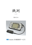
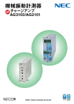
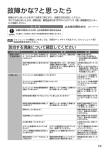
準備
汎用振動計 VM-82A
電池の装着、コード類の接続などのときは必ず電源を OFF にしてから行っ
てください。
簡易取扱説明書
電源
取り扱い上の注意
● 機器の操作は必ず取扱説明書に従ってください。
● 本器を落としたり、振動・衝撃を加えないように注意してください。
● 次のような場所で本体を使用したり、保管したりしないでください。
・ ちりやほこりの多い場所、水のかかる場所。
・ 塩分や硫黄分、化学薬品やガスにより悪影響を受ける恐れのある場
所。
・ 高温、高湿、(50℃、90%RH 以上)直射日光のあたる場所。
・ 衝撃や振動の直接伝わる場所。
● 本器の使用後は次の事項に注意してください。
・ 使用後は必ず電源を切ってください。
・ 1 週間以上使用する予定がない場合は、必ず単 3 形乾電池を取り外
しておいてください。液もれにより故障の原因となる場合がありま
す。
● 本器を分解、改造しないでください。
● 本器および圧電式加速度ピックアップは必ず 1.5∼2 年に一度定期点
検を受けてください。(感度再校正、有料)
● 本器を外部電源で使用するときは必ず指定の AC アダプタ( NC-98 シ
リーズ、別売)をご使用ください。指定以外の AC アダプタを使用する
と動作不良や故障の原因となります。
● 液晶表示画面を指やペンなどで押さないでください。表示不良や動作
不良の原因となります。
● 本器の時計用バックアップ充電池には寿命があります。5 年ごとを目
安に交換してください。充電池の交換については、販売店または当社
サービス窓口までご連絡ください。
● 万一故障した場合には手を加えずに、販売店または当社サービス窓口
までご連絡ください。
● 本器を回転機械の近くで使用する場合は、ケーブルの巻き込みなどに
十分注意してください。
● 本器を廃棄する場合は、国および地方自治体の法律・条例に従ってく
ださい。
本器は単 3 形乾電池(アルカリ乾電池またはニッケル水素充電池)4 本または
AC アダプタ(NC-98 シリーズ、別売)で動作します。
NC-98 シリーズ:AC 100∼240 V に対応
乾電池の装着
本器を乾電池で使用するときは、下図のように単 3 形乾電池を 4 本、+−を
間違えないように正しく入れてください。
乾電池の種類の設定
電池ふたを開けると左上の部分に下図のような電池種類設定スイッチがあ
ります。本器に使用する乾電池の種類に応じてスイッチを切り替えます。
設定した電池の種類に応じた電池残量が画面に表示されます ALKALI.( ア
ルカリ乾電池)または Ni-MH( ニッケル水素充電池)の 2 通りの設定ができ
ます。
ニッケル水素充電池
Ni-MH
使用時
アルカリ乾電池
使用時
各部の名称
正面
ALKALI.
BATTERY
重
要
乾電池の種類は正しく設定してください。
マンガン乾電池は使用できません。
電池の寿命は使用環境により異なりますが、おおよそ下記のようになりま
す。
常温、バックライト消灯時、通信 OFF、連続使用、ピックアップが静穏
な状態であること
アルカリ乾電池(LR6):
約 30 時間
ニッケル水素充電池(HR6)
eneloop pro:
約 32 時間
バックライト点灯時: 消費電流は約 1.5 倍になります。
通信ケーブル接続時: 消費電流は約 1.2 倍になります。
* eneloop pro は、パナソニックグループの登録商標です。
* eneloop pro の充電は、必ず専用の充電器を使用してください。
重
POWERキー
キーロックスイッチ
右側面
コネクタカバー
要
乾電池の極性「+」と「−」を間違えないように正しく入れてください。
4 本とも同じ種類の新しい乾電池を入れてください。
異なる種類や、新旧混ぜての使用は故障の原因となります。
使用しないときは、乾電池を取り出しておいてください。
表示画面の右上に乾電池の残量を示すインジケータが表示されています。
外部電源接続端子使用時は、電池残量は識別されず、常に「 最大」で表示さ
れます。
電池残量最大
外部電源接続端子
直流出力端子
プリンタコネクタ
USBコネクタ
交流出力端子
左側面
電池残量が減ると
右から消えていきます
表示が点滅し始めたら正し
い測定ができません。
新し
い電池と交換してください
電源投入モード
電池ふたを開けると右上の部分に下図のような電源投入モード切り替えス
イッチがあります。通常は「 A」側で使用します。このスイッチを「 B」側に
すると、外部電源接続端子( EXT 6V)への電源供給によって本器の電源を
ON にできます。このときは正面パネルの POWER キーは動作しません。
A
B
ストラップホール
電池残量限界
乾電池の交換時期です
MODE
POWERキー
制御
電源供給による
制御
重
測定モード
要
電源投入モード切り替えスイッチを「 B」側にして使用する場合は、
乾電池を抜いた状態で使用してください( 電池が入っていると、電源
投入モードが正常に動作しません)。
付属の圧電式加速度ピックアップ PV-57I を使用する場合
重
要
接続コードおよび圧電式加速度ピックアップの取り付け・取り外しは
必ず本器の電源を切った状態で行ってください。
4.
付属のカールコード VP-51KI で下図のように本体に接続します。
カールコード
VP-51KI
ピックアップ感度
0.1∼0.99
ACC(m/s2) 1.0∼9.9
加速度
10∼99
測定レンジ
10∼10000
1∼1000
0.1∼100
0.1∼0.99
VEL(mm/s)
1.0∼9.9
速度
10∼99
0.1∼0.99
DISP(mm)
1.0∼9.9
変位
10∼99
100∼10000
10∼1000
1∼100
1∼1000
0.1∼100
0.01∼10
3
3
3
1
周波数範囲
Hz∼1 kHz
Hz∼5 kHz
Hz∼20 kHz
Hz∼100 Hz
3 Hz∼1 kHz
10 Hz∼1 kHz
3 Hz∼500 Hz
10 Hz∼500 Hz
入力信号が回路内で飽和すると[OVER]と表示され、赤色バックライ
トが点灯します。
[OVER]の表示が出ないように、レンジ切り替えスイッチでレンジを
切り替えて、見やすい表示にしてください。
測定データの保存
表示されている測定データを内部のメモリに保存します。
保存される内容は、バーグラフと電池残量を除く下記のデータです。
年月日時分、測定レンジ(フルスケール値)、測定値、測定モード、
指示特性、周波数範囲、過負荷の有無
1. 任意のアドレスにデータを保存する場合は、数値変更スイッチでスト
アアドレスを設定します。
BNCコネクタ
重
入力端子
要
すでにデータが保存されているアドレスに対して再度保存すると、
新しいデータが上書きされます。
圧電式
加速度ピックアップ
PV-57I
設定
設定モード
測 定/設 定 モード 切 り 替 え ス イッチ を 押 す 毎 に、MEAS( 測 定 画 面)と
MODE(設定モード画面)とが切り替わります。
2.
ストアスイッチを押して画面に表示されているデータを保存します。
( ホールドスイッチを押して画面に表示されているデータを一時ホー
ルドして保存することもできます。)
3. ストアスイッチを押すと、瞬間的に表示画面が消えて、データが保存
され、ストアアドレスが 1 つ進みます。
ストアアドレスが 999 のときストアスイッチを押すと、次のストアア
ドレスは 000 になります。
年月日時分
年月日時分および感度の設定
フルスケール
設定モード画面では、設定項目変更スイッチ[▶]を押すごとに、年→月→
日→時→分→圧電式加速度ピックアップの感度→年と変わります。
時刻は 24 時表示です。
過負荷表示
測定値
測定モード
指示特性
リコール表示
ストアアドレス
圧電式加速度ピックアップの
感度表示部
周波数範囲
保存される内容
リコールモード
点滅している個所が変更できます。数値変更スイッチ[▲][▼]キーで数
値を送ってください。[▲]キーで数値が増え、[▼]キーで減ります。2 秒以
上押し続けると早送りになります。
圧電式加速度ピックアップの感度の設定
使用する圧電式加速度ピックアップの感度校正表に記載されている感度に
設定してください。設定する感度は必要に応じて四捨五入してください。
1. 圧電式加速度ピックアップの感度表示部を点滅させます。
2. 数値変更スイッチ[▲][▼]キーで数値を送ってください。[▲]キー
で数値が増え、
[▼]キーで減ります。2 秒以上押し続けると早送りに
なります。表示は 0.10∼99 まで下記のように表示します。
表示は
0.10∼1.0 までの表示は 0.01 ステップで変化
1.0∼10 までの表示は 0.1 ステップで変化
10∼99 までの表示は 1 ステップで変化します。
測定
振動の測定
1.
2.
3.
本器の POWER キーを 2 秒以上長押しして電源を「ON」にします。
測定モード切り替えスイッチで測定モードを選択します。
周波数範囲と指示特性を設定します。
測定モードとピックアップ感度、測定レンジ、周波数範囲の関係は右
上の表のようになっています。
付属の圧電式加速度ピックアップ PV-57I を使用して、ACC で測定す
る場合、測定レンジはフルスケール 1 から 1000 の間で設定できます。
周波数範囲は測定する目的に応じて設定します。
リコールスイッチを押すと、表示画面に[RECALL]と表示されリコール
モードになり、保存されたデータを表示します。再度押すと測定モードに
なります。
1. リコールスイッチを押してリコールモードにします。
2. 数値変更スイッチで読み出すストアアドレスを指定します。
保存されたデータの消去
リコールスイッチを押しながら電源を投入すると、保存されたデータがす
べて消去されます。消去には 5 秒以上かかり、消去中は画面が消灯します。
消去後は測定画面に移行します。
本簡易取扱説明書中の会社名、商品名は一般に各社の登録商標または商標で
す。
リオン株式会社 本社/営業部
http://www.rion.co.jp/
東京都国分寺市東元町 3 丁目 20 番 41 号
〒 185-8533
TEL(042)359-7887(代表) FAX(042)359-7458
東日本営業所
さいたま市南区南浦和 2-40-2 南浦和ガーデンビルリブレ
〒 336-0017
TEL(048)813-5361
FAX(048)813-5364
西日本営業所
大阪市北区梅田 2 丁目 5 番 5 号横山ビル 6F
〒 530-0001
TEL(06)6346-3671
FAX(06)6346-3673
東海営業所
名古屋市中区丸の内 2 丁目 3 番 23 号和波ビル
〒 460-0002
TEL(052)232-0470
FAX(052)232-0458
九州リオン(株) 福岡市博多区店屋町 5-22 朝日生命福岡第 2 ビル
〒 812-0025
TEL(092)
281-5366
FAX(092)
291-2847
リオンサービスセンター株式会社(サービス窓口)
東京都八王子市兵衛 2 丁目 22 番 2 号
〒 192-0918
TEL(042)
632-1122
FAX(042)
632-1140
Vibration Meter VM-82A
CONCISE MANUAL
Precautions
• Operate the unit only as described in this manual.
• Take care not to drop the unit, and protect it from shocks and vibrations.
• Do not store or use the unit in locations where the unit may be subject to
- splashes of water or high levels of dust,
- air with high salt or sulphur content, or other gases or chemicals,
- high temperature (50°C or more), high humidity (90%RH or more),
or direct sunlight,
- directly transmitted vibrations or shock.
• Observe the following precautions after using the unit:
- Always turn the unit to off.
- When the unit is not to be used for a week or longer, remove the
batteries to prevent possible damage caused by battery leakage.
• Do not disassemble the unit or attempt internal alterations.
• Have the unit and the piezoelectric accelerometer checked and serviced
about once every 18 to 24 months. (Sensitivity calibration can be performed at the factory for a fee.)
• When powering the unit externally, use only the specified optional AC adapter
(NC-98C). Using a different adapter may cause malfunction or damage.
• Do not tap the LCD panel for example with your fi nger or a pen, to
prevent possible malfunction or damage.
• The life of the backup battery for the internal clock of the unit is limited.
You should have the battery replaced about once every five years. Regarding replacement of the battery, please contact your supplier.
• In case of malfunction, do not attempt any repairs. Note the condition
of the unit clearly and contact the supplier.
• When using the unit near rotating machinery, take care that cables
cannot be caught in the machinery.
• When disposing of the unit or the accessories, follow national and local
regulations regarding waste disposal.
Controls
Preparations
Always set the power to OFF before inserting batteries and making any
connections.
Power supply
This unit can be powered by four IEC R6 (size AA) batteries or by the
optional AC adapter NC-98C.
NC-98C: For 100 to 240 V AC
Inserting the batteries
Insert four IEC R6 (size AA) batteries with correct polarity, as shown in
the illustration right.
Selecting the battery type
Opening the battery compartment gives access to the battery type selecting
switch (BATTERY) as shown below. Select the battery type used for the unit.
The remaining battery capacity corresponding to the selected battery
type is displayed. Available settings are ALKALI. (alkaline battery) and
Ni-MH (nickel-metal hydride battery).
When using nickel-metal
hydride batteries.
When using alkaline
batteries.
Ni-MH
ALKALI.
BATTERY
Important
Select the correct battery type.
A manganese battery cannot be used.
Front panel
Input connector
The life of the batteries depends on various usage factors. For reference,
some general figures are given below.
Room temperature, backlight off, communication off, continuous use
and connected accelerometer is under quiet conditions.
Alkaline batteries (LR6):
approx. 30 hours
Nickel-metal hydride battery (HR6)
eneloop XX:
approx. 32 hours
Display (LCD)
Level range selector
Measurement mode selector
Display characteristics selector
Frequency range selector
Measurement/setting
mode selector
Setting item selector
Recall key
Numerical setting keys
POWER key
Key lock key
Backlight key
Right side panel
Connector cover
* Eneloop XX is trademarks or registered trademarks of the Panasonic Group.
* Be sure to use a dedicated charger when charging eneloop XX.
When backlight is on, power consumption increases by a factor of about 1.5.
When communication cable is connected, power consumption increases
by a factor of about 1.2.
Important
Take care not to insert the batteries with wrong polarity. Make sure
that all four batteries are of the same type. Do not mix different battery types or old and new batteries. Remove the batteries from the
unit if it is not to be used for a week or more.
The battery indicator in the top right corner of the display shows the
remaining battery capacity. When communication cable is connected,
power consumption increases by a factor of about 1.2.
Full battery
capacity
Reduced number of
segments (from right)
shows decreasing
capacity.
Batteries low.
Should be
replaced soon.
When the indication starts to flash,
correct measurement is no longer
possible. Replace the batteries
immediately.
Power-on mode
External power supply connector
DC output connector
AC output connector
Printer connector
USB connector
Opening the battery compartment gives access to the power-on mode switch
(MODE) as shown below. Normally the “A” position is used. By setting
this switch to “B”, you can have the on/off status of the unit controlled by
the power supplied to the external power supply connector (EXT 6V). In
such a case, the POWER key on the front panel has no effect.
Left side panel
A
B
Hold key Store key
Strap hole
MODE
Power is controlled by
POWER key
Power is controlled by
external power supply
Important
When setting the power-on mode switch to “B”, remove all batteries from the battery compartment. Otherwise the power-on mode
will not operate normally.
When using the supplied piezoelectric accelerometer PV-57I
Important
Make sure that the power of the unit is turn to off before connecting
or disconnecting the cable and accelerometer.
Make the connection with the supplied curled cable VP-51KI, as shown
in the illustration below.
3. Set the frequency range and display characteristics. The relationship
between measurement and accelerometer sensitivity, level range, and
frequency range is as shown in the table below.
In the ACC mode, when the supplied piezoelectric accelerometer
PV-57I is used, the measurement full-scale point can be set to a value
between 1 and 1000. Set the frequency range to a setting which suits
the measurement purpose.
Measurement
mode
ACC (m/s2)
Curled cable VP-51KI
VEL (mm/s)
DISP (mm)
Accelerometer
sensitivity
0.1 to 0.99
1.0 to 9.9
Measurement
range
10 to 10000
1 to 1000
10 to 99
0.1 to 100
0.1 to 0.99
1.0 to 9.9
10 to 99
0.1 to 0.99
1.0 to 9.9
10 to 99
100 to 10000
10 to 1000
1 to 100
1 to 1000
0.1 to 100
0.01 to 10
Frequency range
3 Hz to 1 kHz
3 Hz to 5 kHz
3 Hz to 20 kHz
1 Hz to 100 Hz
3 Hz to 1 kHz
10 Hz to 1 kHz
3 Hz to 500 Hz
10 Hz to 500 Hz
4. If the input signal overloads the circuitry of the VM-82A, the indication
OVER appears and the backlight will come on in red on the display.
Adjust the level range with the level range selector so that OVER does
not appear and the measurement value is easy to read.
BNC connector
Input connector
Storing measurement data
Piezoelectric
accelerometer
PV-57I
Setup
Setting mode
Each push of the MEAS/MODE key toggles between the measurement
mode (MEAS) and setting mode (MODE).
Setting the date/time and sensitivity
In the setting mode, the setting item selector [ ] moves the current
setting item in the order Year
Month
Day
Hour
Minute
Piezoelectric accelerometer sensitivity
Year etc. The time is set and
displayed in 24-hour notation.
Date/time indication
Displayed measurement data can be stored in the internal memory. The
entire display contents except for the bar graph indication and the battery
status indication are stored, as listed below.
Date and time, Measurement range (full-scale value), Measurement
value, Measurement mode, Display characteristics, Frequency range,
Overload yes/no
1. When wishing to store the data in a specific address, use the numerical
setting keys to select the address. Then close the cover again.
Important
When data are stored in an address that already contains data, the
previous data will be overwritten.
2. Press the store key to store the currently displayed data. (It is also
possible to use the hold key to freeze the display and then perform the
store operation.)
3. When the store key is pressed, the display very briefly turns off and
the data are stored. The store address is incremented by 1 count. If
the store address currently is 999 and the store key is pressed, the next
store address will be 000.
Date and time
Full-scale value
Piezoelectric accelerometer
sensitivity indication
Overload indication
Measurement value
Measurement mode
Display screen
Display characteristics
Recall mode indication
Store address
Frequency range
The currently flashing item can be changed. Use the numerical setting
keys [ ] [ ] to change the value. Pressing the [ ] key increases the
value and pressing the [ ] key decreases it. Keeping a key depressed for
2 seconds or more causes the value to change rapidly.
Setting the piezoelectric accelerometer sensitivity
Change the setting at the VM-82A so that it matches the sensitivity indicated on the calibration chart of the used piezoelectric accelerometer.
Round the sensitivity up as necessary.
1. Cause the piezoelectric accelerometer sensitivity item to flash.
2. Use the numerical setting keys [ ] [ ] to change the value. Pressing
the [ ] key increases the value and pressing the [ ] key decreases
it. Keeping a key depressed for 2 seconds or more causes the value to
change rapidly. The display range is 0.10 to 99, with the resolution as
indicated below.
Display resolution 0.10 to 1.0
“0.01” steps
1.0 to 10
“0.1” steps
10 to 99
“1” steps
Measurement
Vibration measurement
1. Press the POWER key for over two seconds to turn the unit on.
2. Select the measurement mode with the measurement mode selector.
Stored items
Recall mode
When the recall key is pressed, the recall mode is activated. The indication
RECALL appears on the display and stored data are displayed. Pressing
the key again switches back to the measurement mode.
1. Press the recall key to activate the recall mode.
2. Use the numerical setting keys to select the address to be recalled.
Clearing stored data
If the unit is turned on while holding down the recall key on the front panel,
all stored data will be cleared. This process will take five seconds or more
and the screen is turned off during the process. When it is completed, the
measurement screen appears.
All company names and product names mentioned in this concise manual are trademarks or registered trademarks of their respective owners.
RION CO., LTD.
3-20-41 Higashimotomachi, Kokubunji, Tokyo 185-8533, Japan
http://www.rion.co.jp/english/
No. 60260 15-02