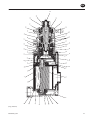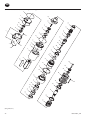
1
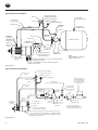
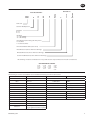
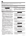
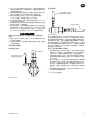
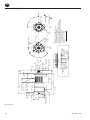
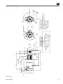
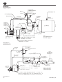
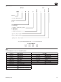
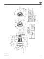
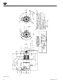
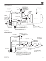
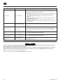
P6633
03532561
Edition 7
January 2014
Starters
Series SS175 and SS350
Installation and Maintenance
Information
EN Installation and Maintenance Information
ZH 安装和维护信息
JA
据付および保守の情報
Save These Instructions
EN
Product Safety Information
Intended Use:
These air starters are intended for use in starting reciprocating internal combustion engines. These starters are designed to be
operated from a remote location after proper installation on the engine requiring starting.
For additional information refer to Air Starters for Internal Combustion Engines Product Safety Information Manual Form 45558624.
Manuals can be downloaded from ingersollrandproducts.com
The Ingersoll Rand Starter is a precision piece of equipment
intended to give efficient, economical performance over a long
period of time. However, as with any product, performance, economy
and durability are determined for the most part by a few simple
common sense procedures that can be recommended only by the
manufacturer and adhered to only by the customer.
Lubrication
WARNING
Do not lubricate starters with flammable or volatile liquids such
as kerosene or jet fuel.
For temperatures above 32° F (0° C), use a good quality SAE 10 non
detergent motor oil.
For temperatures below 32° F (0° C), use diesel fuel. We cannot too
strongly emphasize the importance of proper lubrication of the Starter.
It is the prime requisite for top performance and maximum durability,
yet requires so little time there is really no excuse for disregarding it.
Installation
General Information
1. Always make certain your Air Starter is properly installed. A
little extra time and effort spent in doing a top quality job will
contribute considerably toward a reliable starting system that does
a superior job of starting your engine quickly under all conditions.
2. We strongly recommend that on all vehicular installations, and
on stationary engines subject to vibration, you use hoses of the
specified diameter instead of rigid pipe connections. Vehicle and
engine vibration will soon loosen rigid pipe connections, whereas
hoses will absorb the vibration, and connections will remain tight.
3. In the actual mounting of an Air Starter, it is best to have the hose
connections already made at the receiver, and to have the Starter
end of the hose handy for attaching to the Starter. Wherever
possible-and many times it is necessary attach the air hoses to
the Starter before mounting the Starter on the flywheel housing.
The reason for following this procedure is twofold:
a. After mounting the Starter, it is often impossible to make hose
connections due to space limitations.
b. Once the hoses are attached, they carry some of the weight of
the Starter and make it easier to complete the mounting.
4. The efficiency of an Air Starter can be greatly impaired by an
improper hook-up. Hoses smaller than those recommended will
reduce the volume of air to the motor, and the use of reducers in
the exhaust port will restrict the exhaust and choke the motor.
The number of tees and elbows, and the length of the supply
line should be kept to a minimum, For SS175, use 1” hose or pipe
for supply lines up to 30 feet long; use 1-1/4” hose or pipe if the
supply line is over 30 feet long. For SS350, use 1 -1/4” hose or pipe
for supply lines up to 30 feet long; use 1 -1/2” hose or pipe if the
supply line is over 30 feet long.
5. A leak in any of the connections means that the system will drain
overnight and will have to be repressurized the next morning
by use of another vehicle or compressor. Make your connections
right the first time to avoid unnecessary costs and delays. On all
threaded connections throughout the system, use Ingersoll Rand
No. SMB-441 Sealant, non-hardening No. 2 Permatex or Loctite® *
Pipe Sealant. Teflon tape is not recommended. Always run your air
supply line from the side or top of the receiver-never at or near the
bottom. Moisture in the air collects at the bottom of the receiver
and could cause corrosion in the starter motor or, worse yet, freeze
solid in cold weather so that the Starter would be inoperative.
After all connections have been made, check each joint with a soap
bubble test. There must be no leaks. The slightest leak will cause
the system to lose pressure overnight.
The recommendations outlined in this manual are based on over
30 years of experience in the air and gas starter field. Study these
recommendations and follow them. They can save you considerable
time and expense. This manual should be filed in a permanently
available location.
Either one of two lubrication systems is recommended. For typical
Starter installations where the cranking cycle is less than 10 seconds,
we recommend an Ingersoll Rand No. HDL2 Lubricator installed as
shown on Page 3. Use either diesel fuel or 10W non detergent motor
oil for lubricant. If the cranking cycle is more than 10 seconds, we
recommend the Ingersoll Rand Lubricator No. NL-24-8 installed in
the main air supply line. Use a good quality 10W non detergent oil
and adjust the Lubricator to flow 1 to 2 drops per second.
6. We recommend installation of a “glad hand” for emergency
repressurizing of the system, To keep the “glad hand” clean and
free of dirt, and to protect it from distortion, a second “glad hand”
closed by a pipe plug can be mated to it, or a glad hand protector
bracket can be used.
7. Always mount the Air Starter so that the exhaust port is
downward. This will help prevent any accumulation of water in
the starter motor.
Orientation of the Air Starter
If the factory orientation will not fit your engine due to radial location
of the drive housing, or location of the inlet and/ or exhaust ports,
reorient the Starter as follows:
1. Look at the proper outline drawing on Page 4 or 5 and note
that the drive housing can be located in any one of eight radial
positions relative to the exhaust. The air inlet (motor housing
cover) can be located in any one of four radial positions relative
to the exhaust port.
2. Study the engine mounting requirements, and determine the
required orientation of the drive housing relative to the exhaust
port. The exhaust port should be aimed downward when
installed on the engine. If the drive housing has to be reoriented,
remove the four drive housing cap screws and rotate the drive
housing to the required position.
NOTICE
Do not separate the drive housing from the gear case.
Reinstall the drive housing cap screws and alternately tighten
them to 20 ft-lb (27 Nm) of torque.
3. Now that you have the drive housing properly oriented relative
to the exhaust port, notice whether or not the inlet port will be
favourably located for hose installation. If this must be reoriented,
remove the four motor housing cover cap screws, and rotate the
motor housing cover to its desired position. Reinstall the motor
housing cover cap screws and alternately tighten them to 20 ft-lb
(27 Nm) of torque.
NOTICE
There are eight holes through the motor housing cover, four of
which are not used and are plugged. If the orientation requires
that the plugged holes be used to accommodate the housing
cover cap screws, use a flatend drift to carefully drive the plugs
inward. Then reinstall them in the other four holes.
03532561_ed7
EN
Mounting the Air Starter
Installation of HDL2 Lubricator
1. Study the piping diagrams on page 6. We strongly recommend
that the Starter be connected exactly as shown.
2. The air receiver tank for a Starter installation must have a working
pressure capability equal to or greater than the maximum
pressure at which the Starter will be operated.
3. If you are going to connect to a receiver tank that is already in
service, bleed off the air pressure in the tank.
Mounted on Starter
NOTICE
Air Supply Hose
Lubricant Supply Hose
Prime with Oil at time
of installation.
Bleed off the air pressure through a valve or pet cock. Do not
remove a plug from the tank while the tank is still pressurized. Drain
off any water that may have accumulated in the bottom of the tank.
4. Using a 1” or 1-1/4” short nipple, install the SRV100 or SRV125
Starter Relay Valve on the end of the receiver tank as shown in the
piping diagram.
NOTICE
Make certain the connection is made to the inlet side of the Relay
Valve indicated by the word “IN” cast on the valve body.
5. Install the No. SMB-618 Starter Control Valve on the dash panel
(for vehicular installations) or some other appropriate panel (for
stationary installations).
6. Attach No. TA-STR-100 Starter Instruction Label to the control
panel adjacent to the Starter Control Valve Solenoid.
7. Mount the No. 150BMP-1064 Air Pressure Gauge on or adjacent
to the control panel. It should be located where it is readily visible
to the operator of the Control Valve.
8. Connect the Starter Control Valve to the Relay Valve live air port
with 1/4” hose. Install a Tee in this line with a short feeder hose to
the Pressure Gauge.
(Dwg. TPB789-3)
Mounted at Remote Location
Lubricant Supply Hose
Prime with Oil at time
of Installation
To starter air
supply inlet
NOTICE
Make certain that the hose is connected to the “SUP” side of the
Starter Control Valve.
9. Measure the distance from the Relay Valve on the receiver to the
starter location on the engine to determine the exact length of
1-1/4” or 1” air hose required.
10. Attach the air hose to the outlet side of the Relay Valve, and run the
hose through the frame, etc. to its final position at the starter location.
11.At this point, determine whether or not it is feasible or practical
to attach the hose to the Starter before or after the Starter is
actually mounted. In many cases, it may be necessary to attach
the hose to the Starter before mounting.
12.Liberally grease the teeth on the pinion and ring gear with a
good, sticky gear grease. This will help promote the life of the ring
gear and the drive pinion.
13.Mount the Starter on the flywheel housing. Tighten the mounting
bolts as follows:
a. For 5/8” bolt, 90 ft-lb (122 Nm) of torque
b. For 3/8” bolt, 30 ft-lb (41 Nm) of torque
14.Install a 1/4” hose line from the “DEL” side of the Starter Control
Valve to the “IN” port on the Starter Drive Housing.
15.Install a 1/4” hose line from the “OUT” port on the Starter Drive
Housing to the small pipe tapped port on top of the Starter Relay
Valve.
16.On air-operated Starters, install a Muffler or Road Splash Deflector
in the exhaust port of the Starter. Use No. 150BMA674 Muffler or
No. SS175-A735 Road Splash Deflector on SS175 Starters. Use No.
SS350-A674 Muffler or No. SS350-A735 Road Splash Deflector on
SS350 Starters.
WARNING
If the Starter is gas operated, the exhaust must be piped away to
a location where it will not be ignited or inhaled.
17.Mount an HDL2 Lubricator on or near-the Starter as described
under “Installation of HDL2 Lubricator”.
18.Pressurize the complete starting system and check every
connection with a soap bubble test- There must be no leaks.
(Dwg. TPC494-3)
The HDL2 Lubricator is self-priming and may be installed directly on the
Starter or remotely located. Although the Lubricator is capable of drawing
lubricant from a source 4 ft (1.2 m) lower than the point of installation,
we recommend the lubricating oil lines be as short as practical. We
recommend using the unpressurized fuel return line as the source of
lubricant- However, oil may be supplied from a separate reservoir or the
diesel fuel tank. When the diesel fuel tank is the lubricant source, install
a 10 micron to 50 micron fuel filter (Part No. HDL1-47) in the oil supply
line at the fuel tank. The lubricant line should be tee’d into the fuel return
line with the leg of the tee going to the lubricator directed in the down
direction to insure that the lubricator does not draw air instead of oil.
Mount the HDL2 Lubricator as follows:
1. If you are going to mount the HDL2 Lubricator on the Starter,
remove one of the 3/8” pipe plugs from the Motor Housing Cover
on the Starter, and replace it with the HDL2. If you are going to
mount the HDL2 at a remote location, use two U-bolts and base
clamp available for the Lubricator.
2.If you mounted the HDL2 at a remote location, install a 1/4” hose
from the end of the Lubricator having both a male and female
thread to one of the 3/8” pipe tapped holes on the Starter Motor
Housing Cover.
3. Install a No. 6 hose from the 1/8” NPT oil inlet in the side of the
HDL2 to the unpressurized fuel line, diesel fuel tank or separate
oil reservoir. Tighten the fitting at the Lubricator to 15 to 36 ft-lb
(20.3 to 48.8 Nm) torque. Important: This connection must be
vacuum tight. The thread on the fitting must be clean; assemble it
without sealing compound or Teflon®* tape.
Note: Before initial operation, manually fill the oil supply line.
4. If a separate lubrication reservoir is used, fill it with diesel fuel or
an SAE 10 or 10W light, non detergent motor oil.
* Registered trademark of E. I. Dupont.
03532561_ed7
1 1/4-11 1/2- NPT
Lubricator Connection
both Sides.
74.5
[2.93]
77.5
[3.05]
1” 11 1/2 NPT
48.0
[1.89]
INLET
294.0
[11.57]
227.0
[8.93]
EXHAUST
127.0
[5.00]
1/4”-18 NPT
Control Port
Inlet
1/4”-18 NPT
Control Port
Outlet
291.0
[11.45]
126.0
[4.96]
54.0
[2.12]
16.0
[.62]
69.0
[2.72]
6.0
[.24]
SS175
SAE #1
Pilot
SAE #3
120°
1-D
C
E
G E
01 R
85-
- MODEL CODING -
B
F
2
A
G
0
SAE 3
FLANGE
30°
Control Ports
Exhaust
Orientation Code
Inlet
Type Pinion
Drive
0 2 H
Orientation Options
Inlet
Exhaust Drive Housing
4 @ 90°
4 @ 90°
12 @ 30°
24.0 Pinion Travel
[.94]
Ring Gear Face
19.0
[.75]
92.0
[3.622]
88.7
[3.494]
10.0
[.39]
Size Starter
Gas Sealed
Gearing
Flange type
Rotation
51.0
[2.00]
47.0
[1.85]
J-3
R 73.0
[2.87]
16.7
[.66]
3-Places
K
I
Control
Ports
C
10.4
[.41]
3-Places
1-D
E
B
F
0
SAE 1
FLANGE
2
A
G
Dual
Dimensions
mm
[Inch]
J-3
R 63.5
[2.50]
Left Hand
Rotation
K
I
90°
Right Hand
Rotation
L
H
Notes:
1. Starter should be installed on the enigne with
The exhaust pointed down.
2. Use the set of control ports on the upper side
Of the drive housing. (only drive housings with
Two sets of control ports.)
3. These models are not approved for applications
Where the starter is exposed to the transmission fluid.
4. Drive housing orientation code is based on position
of mounting hole opposite the pinion opening.
5. Standard orientation shown (02H) on SAE3 & (02J) on SAE1
Will be shipped unless otherwise specified.
6. Please read the instructions before attempting
To reorient.
7. Starter weight = 13 kg (29 lbs)
L
H
30°
Control
Ports
EN
Series SS175 with Flange Mounting
(Dwg. TPA929-3)
03532561_ed7
74.5
[2.93]
97.0
[3.82]
1¼ - 11 ½ NPT
60.0
[2.36]
INLET
¼” - 18 npt
Control port
Outlet
356.3
[14.03]
Exhaust
258.3
[10.17]
1¼ - 11 ½ NPT
Lubricationr
connection,
both sides.
¼” - 18 npt
Control port
Inlet
336.5
[13.25]
126.0
[4.96]
54.0
[2.13]
16.0
[.62]
6.0
[.24]
69.0
[2.72]
51.0
[2.01]
47.0
[1.85]
SAE 3
PILOT
SAE 1
120°
C
1 D
E
B
F
G E
01 R
85-
- MODEL CODING -
A
G
O
30°
2
SAE 3
Flange
30°
L
H
Control Ports
Exhaust
Orientation Code
Inlet
Type Pinion
Drive
0 2 H
Orientation Options
Inlet
Exhaust Drive Housing
4 @ 90°
4 @ 90°
8 @ 45°
Size Starter
Gas Sealed
Gearing
Flange type
Rotation
SS350
19.0
[.75]
24.0
[.94] Pinion Travel
Ring Gear Face
Ø 92.0
[3.622]
Ø 88.7
[3.494]
10.0
[.39]
K
I
3-Places
Ø 16.7
[.66]
R 73.0
[2.87]
Ø 10.4
[.41]
3-Places
C
1 D
E
B
F
R 63.0
[2.50]
2
SAE 3
Flange
A
G
O
J
Dual
Dimensions
mm
[Inch]
3
90°
Left Hand
Rotation
K
I
Right Hand
Rotation
L
H
Notes:
1. Starter should be installed on the enigne with
The exhaust pointed down.
2. Use the set of control ports on the upper side
Of the drive housing. (only drive housings with
Two sets of control ports.)
3. These models are not approved for applications
Where the starter is exposed to the transmission fluid.
4. Drive housing orientation code is based on position
Of mounting hole opposite the pinion opening.
5. Standard orientation shown (02H) on SAE3 & (02j) on SAE1
Will be shipped unless otherwise specified.
6. Please read the instructions before attempting
To reorient.
7. Starter weight = 13 kg (29 lbs)
J
Control
Ports
Control
Ports
EN
Series SS350 with Flange Mounting
(Dwg. TPA930-3)
03532561_ed7
EN
Piping Diagram
Typical Vehicular Installation:
Starter Control Valve
150BMP-2451B (24V)
Y54-23
From Starter
Control Valve
To Relay Valve
AEROQUIP
4411-4S
Hose #4
Hose #4
Check Valve
150BMP-1056
Y54-23
Hose #4
AEROQUIP
2X 4411-4S
Air Supply
from Compressor
Starter Control Valve
150BMP-1051B (24V)
Air Pressure Guage
Y54-23
1¼” or 1” Hose
AEROQUIP
4411-4S
ST400-411
AEROQUIP
2X 4411-4S
Air Receiver Tank
AEROQUIP
2024-20-16S
“OUT” port
JIC 37° Adapter
¼” N.P.T
Y54-3
Lube Oil Line
HDL3 Lubricator
Mount Lubricator in
pipe tapped hole
“IN” port
JIC 37° Adapter
¼” N.P.T
1¼” or 1” Nipple
SRV125T
Relay Valve
150BM - A674 Muffler or SS175 - A735 Road Splash
Deflector for 22175
NOTE:
Use IR SMB-441 Sealant On
All Pipe Connections.
SS350 - A674 Muffler or SS350 - A735 Road Splash
Deflector for SS350
(Dwg. TPB715-1)
Typical Stationary Installation:
Starter Control Valve SMB-618
#4 Hose or 1/4”
Tubing
For gas operation connect
Exhaust to safe area
Air Pressure Guage
#4 Hose or 1/4”
Tubing
Pressure Regulator
(Maximum setting not
to exceed pressure
rating shown on Starter
Nameplate)
Relief Valve
(set at 15 PSI aboe regulator setting)
#4 Hose or 1/4”
Tubing
JIC 37° Adapter
1-1/2” NPT to1-1/4”
or 1” Hose
1-1/2”
Pipe
JIC 37°
Adapter
1/4” NPT
For gas operation
the Relief Valve
must be connected
to a safe area.
1-1/2”’
Pipe
“OUT” port
JIC 37° Adapter
1/4” NPT
“IN” port
JIC 37°
Adapter
1/4” NPT
Lubricator NL24-8
JIC 37° Adapter
1-1/4” or 1” NPT
Air Starter
Model SS175 (1” NPT Inlet)
or model SS350 (1-1/4” Inlet)
JIC 37°
Adapter
1-1/2” Pipe
SRV150 1-1/2” or
SRV150SS 1-1/2”
Relay Valve
Air Strainer
20BM-A267AT
If used for gas application
entire system should meet all
local standards and ordinances.
For Gas operation, exhuast must be connected to a safe area. For
air, use SS175-A735 Road Splash Deflector or 150BM-A674 Muffler
on SS175 models. Use SS350-A735 Road Splash Deflector or SS350
A674 Mufflers on SS350 models.
(Dwg. TPA942-1)
03532561_ed7
EN
Model Code Identification
Orientation *
Basic Model Number
SS175
SS350
G
B
E
01
03
R
L
15
31
32
etc.
0
0
1
2
3
A
B
C
D
etc.
Frame Size
Sealed for Gas Operation
Gear Ratio
B = 2.1
E = 3.1
Mounting
01 = SAE 1 Flange
03 = SAE 3 Flange
Pinion Rotation (when facing the drive pinion)
R = Clockwise
L = Counterclockwise
Pinion Part Number Suffix (SS350-13-15)
Inlet Orientation (refer to dimension drawings)
Exhaust Orientation (refer to dimension drawings)
Control Inlet Orientation (refer to dimension drawings)
* The following orientation combinations are not possible because of space limitations and other considerations:
ON FLANGE MOUNT STARTERS
0-0-E
0-0-C
0-0-K
0-0-I
0-1-H
0-1-F
0-1-B
0-1-L
0-2-E
0-2-C
0-2-K
0-2-I
0-3-H
0-3-F
0-3-B
0-3-L
Accessories
The following accessories are available for use on installations involving an SS175 or SS350 Starter:
Part Number
SMB-618
HDL2
Name of the Part
Part Number
Name of the Part
for SS175
Starter Control valve
Lubricator
150BM-A674
Muffler
HDL1-47
Lubricator Filter
SS175-A735
Road Splash Deflector
NL-24-8
Air Line Lubricator
SMB-441
Sealant for Pipe Threads
SRV100
SS175-HN16
1” Relay Valve
1” Pipe Nipple
for SS350
150BMP-1051B
12V Solenoid valve
150BMP-2451B
24V Solenoid Valve
SS350-A674
Muffler
150BMP-1054
Combination Pr. Relief/Check Valve
SS350-A735
Road Splash Deflector
150BMP-1056
Check Valve
150BMP-1064
Pressure Gauge
K4U-A267AT
1-1/4” Air Strainer
20BM-A267AT
1-1/2” Air Strainer
150BMP-1067
Drain Valve
SRV150-SS
SRV125
1-1/4” Relay Valve
SS350-HN20
1-1/4” Pipe Nipple
1-1/2” Relay Valve (Stainless Steel)
(for gas applications where required)
03532561_ed7
ZH
产品安全信息
用途:
此类空气启动器应用于往复式内燃机的启动。此类启动器应在正确安装到需要启动的内燃机上后,进行远程操作。
更多信息请参见内燃机空气启动器产品安全信息手册表 45558624。
手册可从 www.irtools.com 下载。
Ingersoll Rand 起动器是一种精密装置,可长时间提供高效和经济性能。但是,如同任何产品一样,性能、经济性和耐用性大多都是由
少数简单的常识步骤确定,只能由制造商建议,并仅由客户遵守。本手册中略述的建议根据 30 多年以来在空气和气动起动器领域总结
的经验。学习和采纳这些建议。它们可让您节省大量时间和费用。本手册应存放在固定位置。
润滑
警
告
不要使用煤油或喷气机燃油等易燃、易挥发的液体来润滑起动器。
若温度高于 32° F (0° C), 可使用优质 SAE 10 非去垢性机油。
若温度低于 32° F (0° C), 可使用柴油。 我们不会过度强调正确润
滑起动器的重要性。这对达到最高性能和最大耐用性至关重要,
然而所需时间如此之少以致没有理由不对其予以处理。
建议使用以上两种润滑系统中的任何一种。对于典型的起动器装
置(盘车时间低于 10 秒),我们建议使用 Ingersoll Rand No.
HDL2 润滑器(按 页 3 上所示的方式安装)。使用柴油或 10W 非
去垢性机油进行滑润。如果盘车时间高于 10 秒,我们建议使用已
安装在主空气供应管线中的 Ingersoll Rand 润滑器 No. NL-24-8。
使用优质 10W 非去垢性油,并调整润滑器以使其每秒涌出 1
至 2 滴。
安装
一般信息
1. 确保正确安装气动起动器。花费少量额外时间和精力完成的出
色工作将可造就一个可靠的起动系统,而该系统可在所有情况
下快速起动发动机。
2. 我们强烈建议在受到振动的所有车载装置和固定发动机上,您
可以使用指定直径的软管而非刚性连接管。车辆和发动机振动
会很快松动刚性管连结,而软管会缓冲此振动,从而使连结保
持紧固。
3. 在实际安装气动起动器的过程中,最好已在接收器中连接软
管,并使软管的起动器末端便于连接到起动器。在飞轮外壳上
安装起动器之前,很多时候都需要在可行之处将空气软管连接
到起动器。对于为何要遵循该步骤,有以下两个方面的原因:
a. 在安装起动器之后,常常因空间限制而无法连接软管。
b. 在连接软管之后,它们会支撑起动器的部分重量,以便更
加容易完成安装。
4. 连结不当会大大削减气动起动器的效率。使用小于所建议尺寸
的软管将会导致进入到马达中的压缩空气量不足,而且使用排
气管端口中的渐缩管将可以限制排气,同时会堵塞马。三通和
弯头的数量以及供应管线的长度都应最小化。对于 SS175,如
果供应管线长达 30 英尺,可使用 1” 软管或管道;如果供应管
线超过 30 英尺,可使用 1-1/4” 软管或管道。对于 SS350, 如果
供应管线长达 30 英尺,可使用 1 -1/4” 软管或管道;如果供应
管线超过 30 英尺,可使用 1 -1/2” 软管或管道。
5. 任何连接装置出现泄漏状况都表明,系统将会整夜排放并必须
在第二天早上通过使用另一台车辆或压缩机来增压。第一次要
正确连接以避免不必要的费用和延迟。在整个系统的所有螺纹
连接装置上,使用 Ingersoll Rand No. SMB-441 Sealant, 非硬化
的 No. 2 Permatex 或 Loctite®* 管道密封剂。建议不要使用特氟
隆胶带。务必从接收器的侧面或顶部运行空气供应管线,切勿
在底部或底部附近运行。空气中的水分聚集在接收器底部,便
可能会腐蚀起动器电动机或在寒冷天气下凝结成固体(更为糟
糕的情况)以致无法使用。在进行所有连接后,可使用肥皂气
泡测试检查每个接头。确保不会出现渗漏状况。稍有泄漏便会
导致系统很快失压。
6. 对于系统的紧急增压,我们建议使用 “glad hand” 安装。要保
持 “glad hand” 干净和没有污物,以及避免变形,可将其连接
到由管道塞子密封的第二个“ glad hand”, 或可使用 “glad hand”
保护器托架。
7. 总是安装气动起动器以便排气管端口朝下。这将有助于预防起
动器电动机中出现水份积聚现象。
气动起动器的定向
如果工厂定向因传动箱的径向位置或进气口和 / 或排气管端口而
无法安装发动机,请按如下方式重新定向起动机:
1. 请参见 页 4 或 页 5 上的略图,并且注意传动箱可位于与排气
装置相对 8 个径向位置的任一处。进气口(电动机外壳盖)可
位于与排气管端口相对的 4 个径向位置中的任一处。
2. 学习发动机安装要求,并确定与排气管端口相对的传动箱的所
需定向。当在发动机上安装时,排气管端口应向下。如果传动
箱必须重新定向,可卸下 4 个传动箱有头螺丝,然后将传动箱
旋转至所需位置。
注
意
切勿分开传动箱和齿轮箱。
重新安装传动箱有头螺丝,并交替地将其旋紧至 20 英尺-磅
(27 牛米)扭矩。
3. 既然已正确定向与排气管相对的传动箱,注意进气口是否处于
有利于软管安装的位置。如果这必须重新定向,可卸下 4 个电
动机外壳盖有头螺丝,然后将电动机外壳盖旋转至所需位置。
重新安装电动机外壳盖有头螺丝,并交替地将其旋紧至 20 英
尺-磅(27 牛米)扭矩。
注
意
马外壳盖中有 8 个孔,其中 4 个无用,因此用塞子堵住。如果定
向要求将堵塞孔用以安装外壳盖有头螺丝,使用平端移动以小心
向内驱动塞子。然后将其重新安装在其他 4 个孔中。
安装气动起动器
1. 学习 页 6 上的管道布置图。我们强烈建议按如图所示的方式
准确连接起动器。
2. 起动器装置的空气储气罐必须具有工作压力性能 (等于或大于
起动器将会操作的最大压力)。
3. 如果要连接到正在工作的储气罐, 可排出箱中的气压。
注
意
通过阀或旋塞排出气压。当储气罐仍处于增压状态时,切勿从罐上拔
下塞子。排出积聚在罐底部的水份。
4. 使用 1” 或 1-1/4” 的短螺纹接套将 SRV100 或 SRV125 起动器主
启动阀安装在接收箱末端,如管道布置图所示。
注
意
确保连接到主启动阀的进口侧(在阀座上标注为字母 “IN” )。
5. 请在仪表板上(车载装置)或某些其他相应面板上(固定装
置)安装 No. SMB-618 起动器控制阀。
6. 将 No. TA-STR-100 起动器说明标签贴在邻近起动器控制阀电磁
阀的控制面板上。
7. 将 No. 150BMP-1064 气压计安装在控制面板上或邻近控制面板
处。它应位于控制阀操作者容易看到的地方。
8. 将起动器控制阀连接到具有 1/4” 软管的主启动阀活动空气端口
上。使用短软管将此管道中的三通管安装到压力表上。
注
意
确保将软管连接到起动器控制阀的 “SUP” 侧。
9. 测量储气罐的主启动阀和发动机的起动器位置之间的距离以确
定所需的 1-1/4” 或 1” 进气软管的确切长度。
10.将进气软管连接到主启动阀的出口侧,并使软管从机架等穿过
起动器处的最终位置。
03532561_ed7
ZH
11. 在此,可在实际安装起动器之前或之后,确定将软管连接到起
动器是否可行或实用。 在多数情况下,可能需要在安装之前
将软管连接到起动器。
12.请使用优质粘性齿轮润滑油来充分润滑小齿轮和环形齿轮上的
齿轮。这将有助于延长环形齿轮和传动小齿轮的寿命。
13.将起动器安装在飞轮外壳上。按以下方式旋紧装配螺栓:
a. 对于 5/8” 螺栓,扭矩是 英尺-磅(122 纳米)
b. 对于 3/8” 螺栓,扭矩是 30 英尺-磅(41 纳米)
14.请在起动器控制阀的“DEL”侧和起动器传动箱上的 “IN” 端
口之间安装 1/4” 软管管线。
15. 在起动器传动箱的 “OUT” 端口和起动器继动阀顶端的小管道分
接部分之间安装 1/4” 软管管线。
16.在气动起动器上,请在起动器的排气管端口中安装消音器或公
路防溅导向板。使用 SS175 起动器上的 No. 150BMA674 消音器
或 No. SS175-A735 公路防溅导向板。使用 SS350 起动器上的
No. SS350-A674 消音器或 No. SS350-A735 公路防溅导向板。
警
告
如果以气动方式操作起动器,必须将废气排至无法燃烧或吸入
的地方。
17.根据“安装 HDL2 润滑器”说明,将 HDL2 润滑器安装在起动
器上或起动器附近。
18. 加压整个起动系统,并使用皂气泡测试检查各个连接。确保不
会出现渗漏状况。
安装 HDL2 润滑器
在起动器上安装
安装时需要上油的主
要润滑剂供应软管。
起动器气源进口
(Dwg. TPC494-3)
HDL2 润滑器可自动充满,并可直接安装在起动器上或位于远处。
虽然润滑器能从较安装点低 4 英 (1.2 米) 的油源处吸油,但我们
建议使用最短的润滑油管道。我们建议使用非增压回油管线作为
润滑剂的来源 –但是,也可从单独接收器或柴油箱供油。当柴油
箱是润滑油来源时,可在燃油箱的油供应管线中安装一个 10 微米
至 50 微米的燃油过滤器(部件号 HDL1-47)。润滑剂供应管线应
装入具有 T 形管支管(向下流入润滑器)的回油管线,以确保润
滑器无法吸气而不是油。
按以下方式安装 HDL2 润滑器:
气源软管
安装时需要上油的主
要润滑剂供应软管。
在远处安装
1. 如果要在起动器上安装 HDL2 润滑器,可从起动器的电动机外
壳盖取下 3/8” 管道塞子,然后将其更换为 HDL2。如果要在远
处安装 HDL2,可使用润滑器可用的两个 U 形螺栓和压板。
2. 如果在远程位置安装了 HDL2,便可在具有外螺纹和内螺纹的
滑润器末端和起动器电动机外壳盖上的3/8” 管道分接孔之间安
装 1/4” 软管。
3. 请在 HDL2 侧的 1/8” NPTF 油进口到非增压燃油管线、柴油箱或
单独油箱之间安装 6 号软管。将润滑器的装置旋紧至 15 至 36
英寸-磅(20.3 至 48.8 纳米)扭矩。重要信息:该连接必须是
真空密封。装置的螺纹必须清洁;不可使用密封剂或 Teflon®*
胶带安装,注意:在首次操作之前,可手动将油注入供油管线
中。
4. 如果使用单独润滑剂储存罐,可向其中注入柴油或 SAE 10 或
10W 轻质非去垢剂型机油。
* E. I. Dupont 的注册商标。
(Dwg. TPB789-3)
03532561_ed7
10
1 1/4-11 1/2- NPT
润滑器连接两侧
74.5
[2.93]
77.5
[3.05]
1” 11 1/2 NPT
48.0
[1.89]
入口
294.0
[11.57]
排气口
127.0
[5.00]
227.0
[8.93]
1/4" - 18 N.P.T. 控制气口进口
1/4" - 18 N.P.T. 控制气口出口
291.0
[11.45]
126.0
[4.96]
54.0
[2.12]
16.0
[.62]
69.0
[2.72]
6.0
[.24]
SS175
SAE #1
SAE #3
导向
G E
01 R
C
E
B
F
30°
2
A
G
0
SAE 3
法兰
控制油口
排气装置
定向代码
入口
小齿轮类型
驱动形式
0 2 H
传动箱
1-D
12 @ 30°
120°
85-
- 型号编码 -
4 @ 90°
定向选项
入口 排气装置
4 @ 90°
24.0
小齿轮行程
[.94]
飞轮齿圈表面
19.0
[.75]
92.0
[3.622]
88.7
[3.494]
10.0
[.39]
起动器尺寸
密封气体
齿轮
法兰类型
旋向
51.0
[2.00]
47.0
[1.85]
J-3
R 73.0
[2.87]
Ø 16.7
[.66] 3 个地方
K
I
控制气口
C
10.4
[.41]
3 个地方
1-D
E
B
F
0
SAE 1
法兰
2
A
G
J-3
R 63.5
[2.50]
K
I
90°
顺时针旋转
L 逆时针旋转
H
双
尺寸
mm
[Inch]
注意:
1. 应该使排气口向下在发动机上安装起动器。
2. 使用传动箱上侧控制气口的设置。
(仅适用具有两个控制气口的传动箱。)
3. 这些型号不能用于起动器暴露在变速器液中的情况。
4. 传动箱定向代码取决于小齿轮开口相反方向的安装孔位置。
5. 除非另行指定,否则将以在 SAE3 上的 (02H) 和 SAE1 上的 (02J) 显示的标准方向进行装运。
6. 请在尝试重新定向前阅读说明。
7. 起动器重 = 13 千克(29 磅)
L
H
30°
控制气口
ZH
系列 SS175 (带法兰装置)
(Dwg. TPA929-3)
03532561_ed7
03532561_ed7
74.5
[2.93]
97.0
[3.82]
1¼ - 11 ½ NPT
60.0
[2.36]
入口
¼” - 18 N.P.T. 控制气口出口
258.3
[10.17]
1¼ - 11 ½ NPT
356.3
[14.03]
排气口
润滑器连接两侧。
¼” - 18 N.P.T. 控制气口进口
336.5
[13.25]
126.0
[4.96]
54.0
[2.13]
16.0
[.62]
6.0
[.24]
69.0
[2.72]
51.0
[2.01]
47.0
[1.85]
SAE 3
导向
SAE 1
G E
01 R
1
C
D
E
85-
B
F
A
G
O
2
SAE 3
法兰
30°
控制油口
排气装置
定向代码
入口
小齿轮类型
驱动形式
0 2 H
传动箱
8 @ 45°
120°
- 型号编码-
定向选项
入口 排气装置
4 @ 90°
4 @ 90°
起动器尺寸
密封气体
齿轮
法兰类型
旋向
SS350
19.0
[.75]
24.0
[.94] 小齿轮行程
飞轮齿圈表面
Ø 92.0
[3.622]
Ø 88.7
[3.494]
10.0
[.39]
30°
L
H
K
I
Ø 16.7
[.66]
3 个地方
R 73.0
[2.87]
E
B
Ø 10.4
[.41]
3 个地方
C
1 D
F
R 63.0
[2.50]
2
SAE 3
法兰
A
G
O
J
3
逆时针旋转
K
I
90°
顺时针旋转
L
H
双
尺寸
mm
[Inch]
注意:
1. 应该使排气口向下在发动机上安装起动器。
2. 使用传动箱上侧控制气口的设置。
(仅适用具有两个控制气口的传动箱。)
3. 这些型号不能用于起动器暴露在变速器液中的情况。
4. 传动箱定向代码取决于小齿轮开口相反方向的安装孔位置。
5. 除非另行指定,否则将以在 SAE3 上的 (02H) 和 SAE1 上的 (02J) 显示的标准方向进行装运。
6. 请在尝试重新定向前阅读说明。
7. 起动器重 = 13 千克(29 磅)
J
行程控制气口
控制气口
ZH
系列 SS350 (带法兰装置)
(Dwg. TPA930-3)
11
ZH
管道布置图
典型的车载安装:
起动器控制阀 150BMP-2451B (24V)
Y54-23
始于起动器控制阀
进至主启动阀
压力表
AEROQUIP
4411-4S
#4 号软管 #4号软管
1¼” 或 1” 软管
单向阀
150BMP-1056
Y54-23
#4 号软管 AEROQUIP
2X 4411-4S
AEROQUIP
2X 4411-4S
“出口”端 JIC 37° 接头 ¼” N.P.T.
来自压缩机的气源
起动器控制阀 150BMP-1,051B (24V)
Y54-23
AEROQUIP
4411-4S
ST400-411
空气储气罐
AEROQUIP
2024-20-16S
Y54-3
润滑油管道
HDL3 润滑器
1¼” 或 1” 螺纹接套 SRV125T 主启动阀
在管道分接孔中安装润滑器
“进口”端 JIC 37°
接头 ¼” N.P.T.
注意:
在所有管道连接处使用 IR SMB-441 密封胶
150BM - A674 消声器或 SS175 - A735 公路防溅板(针对 22175)
SS350 - A674 消声器或 SS350 - A735 公路防溅板(针对 SS350)
(Dwg. TPB715-1)
典型的固定安装:
起动器控制阀 SMB-618
#4 号软管或 1/4” 管道
对于气体操作,
要将排气装置连接到安全的地方
气压计
#4 号软管或 1/4” 管道
减压器
(最大设置不超过
起动器商标上显
示的额定压力)
安全阀
(以超出调节器设置的 15 Psi 设置)
#4 号软管或 1/4” 管道
JIC 37° 接头 1-1/2”
N.P.T. 至 1-1/4” 或
1” 软管
1-1/2" 管道
JIC 37º 接头
1/4" N.P.T.
对于气体操作,
必须将主启动阀连
接到安全地方。
1-1/2" 管道
润滑器 NL24-8
“出口”端 JIC 37º 接头 1/4" N.P.T.
“进口”端 JIC 37º 接头 1/4" N.P.T.
JIC 37° 接头 1-1/4” 或 1” N.P.T
1-1/2" 管道
JIC 37° 接头
气动起动器型号 SS175(1” N.P.T. 进口)
或型号 SS350(1-1/4” 进口)
SRV150 1-1/2” 或 SRV150SS 1-1/2” 主启动阀
空气过滤器
20BM-A267AT
如果用于气体应用装置,
则整个系统应满足所有
当地标准和法规的要求。
对于气体操作,必须将排气装置连接到安全地的地方。 对于气动型,使用 SS175-A735 公路防溅导向板或在 SS175 型号上的150BM-A674 消声器。 使
用 SS350-A735 公路防溅导向板或在SS350 型号上的 SS350 A674 消声器。
(Dwg. TPA942-1)
12
03532561_ed7
ZH
型号代码标识
定向*
基本型号
SS175
SS350
G
B
E
01
03
R
L
15
31
32
etc.
0
0
1
2
3
A
B
C
D
etc.
框架尺寸
对于天然气操作的密封
齿轮齿数比
B = 2.1
E = 3.1
安装 01 = SAE 1 法兰
03 = SAE 3 法兰
小齿轮旋转(在朝向传动小齿轮时)
R = 顺时针方向
L = 逆时针方向
小齿轮零件号码后缀 (SS350-13-15)
进口方向(参见尺寸图示)
排气方向(参见尺寸图示)
控制进口方向(参见尺寸图示)
* 由于空间有限和对其他因素的考虑,以下方向不可能结合使用:
关于法半装置起动器
0-0-E
0-0-C
0-0-K
0-0-I
0-1-H
0-1-F
0-1-B
0-1-L
0-2-E
0-2-C
0-2-K
0-2-I
0-3-H
0-3-F
0-3-B
0-3-L
配件
以下附件涉及安装 SS175 或 SS350 起动器时可以使用:
部件的编号
SMB-618
HDL2
HDL1-47
NL-24-8
SMB-441
150BMP-1051B
150BMP-2451B
150BMP-1054
150BMP-1056
150BMP-1064
K4U-A267AT
20BM-A267AT
150BMP-1067
SRV150-SS
03532561_ed7
部件名称
起动器控制阀
润滑器
润滑剂过滤器
空气管道润滑器
管螺纹密封胶
12V 电磁阀
24V 电磁阀
组合阀 安全/单向阀
单向阀门
压力表
1-1/4” 空气过滤器
1-1/2” 空气过滤器
排水阀
1-1/2” 主启动阀(不锈钢)
(根据需要使用气体应用装置)
部件的编号
150BM-A674
SS175-A735
SRV100
SS175-HN16
SS350-A674
SS350-A735
SRV125
SS350-HN20
部件名称
对于 SS175
消声器
公路防溅导向板
1” 主启动阀
1” 管道螺纹接套
对于 SS350
消声器
公路防溅导向板
1-1/4” 主启动阀
1-1/4” 管道螺纹接套
13
JA
製品に関する安全性
製品に関する安全性
これらのエアスターターは、往復内燃機関の始動に使用することを目的としています。これらのエアスターターは、始動させる必要のある往復内
燃機関に正しく取り付けた後、離れた場所から操作するように設計されています。
詳細は、
「内燃機関用エアスターター製品安全情報説明書 45558624」
を参照してください。
www.irools.com から説明書をダウンロードすることができます。
Ingersoll Rand 始動装置は、長期間に渡って効率のよい、経済的な
性能を示すことを目的とした精密機器です。
しかし、
どの製品もそう
であるように、性能、経済性および耐久性は、大部分が、製造者によ
ってのみ推奨でき、顧客によってのみ支持できる 2 ~ 3 の単純な常
識的な手順によって決定されます。
この取扱説明書で概説されている推奨内容は、空気およびガスの
始動装置の分野に於ける30年以上に渡る経験に基いています。
これ
らの推奨内容を検討し、従ってください。
これらの推奨内容によって
時間と費用の節約が可能になります。
この取扱説明書は、永久に利
用できる場所にファイルしてください。
潤滑
始動装置の潤滑に、灯油またはジェット燃料のような可燃性または
揮発性液体を使用しないでください。
温度が 32° F (0° C) 以上の場合, 高品質の SAE 10 非洗浄性モータ
ー オイルを使用します。
温度が 32° F (0° C) を下回る場合、
ディーゼル燃料を使用します。始
動装置の適切な潤滑の重要性は、
どれほど強調しても強調し過ぎる
ことはありません。適切な潤滑は、最高の性能および最大の耐久性
の第一要件であり、
しかもほとんど時間を必要としないのでこれを
軽視する理由は全くありません。
2 種類の潤滑システムのどちらも推奨します。
クランキングサイクル
が 10 秒以下の典型的な始動装置再組付けの場合、Ingersoll Rand
No. HDL2 Lubricator を ページ 3 に示されるように再組付けするこ
とを推奨します。潤滑油には、ディーゼル燃料または 10W 非洗浄性
モーター オイルを使用します。
クランキング サイクルが10 秒を超え
る場合、Ingersoll Rand Lubricator No. NL-24-8 を主要給気ラインに
再組付けすることを推奨します。良質の 10W 非洗浄性オイルを使用
して Lubricator の流速を毎秒 1 ~ 2 滴に調整します。
再組付け
一般情報
1. ご使用の空気始動装置が正しく再組立されているか常に確認し
ます。最高品質の仕事の実行に費やした僅な、余分な時間およ
び努力は、
ご使用のエンジンをすべての条件下で素早く始動さ
せるという優れた仕事を実行する、信頼できる始動システムに
かなり貢献します。
2. すべての車両への再組付けおよび振動に晒される固定エンジ
ンについて、配管による固定した接続を行うのでなく、規定の口
径のホースを使用することを強く推奨します。車両およびエンジ
ンの振動により固定した配管接続は直ぐ緩みますが、ホースの
場合、振動を吸収し、接続は強固なままです。
3. 空気始動装置を実際に取り付ける場合は、ホースは前以て受け
手側での接続を済ませ、ホースの始動装置側の端は、始動装置
に取り付けられるように近くに置いておくのが一番良い方法で
す。可能な場合いつでも、
また必要なときは何度でも、始動装置
をフライホイール筐体に取り付ける前に空気ホースを始動装置
に取り付けます。
この手順に従う理由は、二つあります。
a. 始動装置を取り付けた後、ホースの接続は、
スペースの制限
からしばしば不可能となります。
b. ホースは一旦取り付けられると、始動装置の重量の何割かを
支え、取り付けを更に容易にします。
4. [空気始動装置] の効率は、不適切な接続によって非常に損なわ
れることがあります。推奨したものより小さいホースをご使用に
なった場合、モーターへの空気量は、減少し、排気ポートに減速
機を使用した場合、排気を制限し、モーターを詰まらせます。T分
岐と肘継手の数および供給ラインの長さは、最小限に保ってく
ださい。SS175 の場合、30 フィート長までの供給ラインには1イ
ンチのホースまたは導管を使用し、30フィート長を超える場合
は、1-1/4 インチのホースまたは導管を使用します。SS350 の場
合、30 フィート長までの供給ラインには1-1/4 インチのホースま
たは導管を使用し、30フィート長を超える場合は、1-1/2 インチの
ホースまたは導管を使用します。
5. どこかの接続部に漏れがあるということは、
システムが一晩中空
気を流出しているということであり、翌日の朝、別の車両または
コンプレッサを使用して再度圧力を上げる必要があります。接
続部を始めから確かで間違いないようにして、不要なコストや
遅れの発生を避けます。
システム全体のすべてのネジ接続は、
Ingersoll Rand No. SMB-441 シーラント非硬化剤 No. 2 Permatex
または Loctite®* パイプ シーラントを使用します。テフロンテー
プは推奨しません。
14
ご使用の給気ラインを常に受け器の側面または上端から入るよ
うにし、決して底部またはその付近から入ることのないようにし
ます。空気内の湿気は、受け器の底部で集まり、始動装置モータ
ー内の腐食の原因になる可能性があり、
さらに悪い場合、寒い
気候で固く凍り始動装置が運転できなくなります。すべての接続
を終了した後に、各接合部をせっけん泡試験でチェックします。
漏れが全く無いことが必要です。ほんの僅かな漏れであっても
一晩中、
システムの圧力損失を引き起こします。
6. システムの緊急再加圧用に「友好的な握手」の再組付けを推奨
します。
「友好的な握手」を清浄かつ埃の無い状態に保ち、変形
から防ぐために、パイプ栓で閉じられる二番目の「友好的握手」
を仲間入りさせることが可能であるかまたは友好的握手保護ブ
ラケットを使用できます。
7. 空気始動装置は、常に、排気ポートが下に向くように取り付けま
す。
こうすると、始動装置モーターに水が溜まるのを防ぐのに役
立ちます。
空気始動装置の向き
工場で設定された向きが、駆動筐体の放射状配置または吸気/排気
ポートの配置のためにご使用のエンジンに合わない場合、以下のよ
うにして始動装置の向きを変えてください:
1. ページ 4 または ページ 5 にある適切な外形寸法図をご覧にな
り、駆動部筐体が排気管に対し、8箇所の放射状位置のどの位置
にも配置できることにご注目ください。吸気口 (モーター筐体カ
バー) は、排気ポートに対し 4箇所lの放射状位置のどの位置に
も配置できます。
2. エンジンの取り付け要求を検討し、排気ポートに対する駆動部
筐体の必要な向きを決定します。排気ポートは、エンジンに再組
付けするとき、下向きにしてください。駆動部筐体の向きを変え
る必要がある場合、4本の駆動部筐体キャップ ネジを外し、駆動
部筐体を要求される位置に回転させます。
駆動部筐体を変速装置から分離させないでください。
駆動部筐体キャップ ネジを元のように再組み付けして、
20 ft-lb (27 Nm) のトルクで交互に締め付けます。
03532561_ed7
JA
3. これで、駆動筐体は、排気ポートに対し、正しい向きにできたの
で、吸気ポートがホースの再組付けに対し好ましい配置となっ
ているか注意します。
これで向きを変える場合、4 本のモーター
筐体カバーキャップネジを外し、モーター筐体カバーを希望の
位置に回転させます。駆動部筐体カバー キャップ ネジを元のよ
うに再組み付けして、20 ft-lb (27 Nm) のトルクで交互に締め付
けます。
モーター筐体カバーには8 個の穴があり、使用しないものには栓を
します。向きによって、栓をした穴が筐体カバー キャプ ネジの収納に
使用することが必要になった場合、水平方向のすき間を使用して慎
重に栓を押し込みます。
それから、駆動部筐体キャップ ネジを残りの
4箇所の穴に元のように再組付けします。
空気始動装置の取り付け
1. ページ 6 の配管図を検討します。始動装置が表示された通り正
しく接続されることを強く推奨します。
2. 始動装置再組付け用の空気受けタンクは、始動装置が運転され
る最大圧力以上の動作圧力性能を有する必要があります。
3. 既に使用中の受けタンクに接続しようとする場合、
タンク内の空
気圧を徐々に減らして無くします。
空気圧をバルブまたはコックを通して徐々に減らして無くします。
タン
クにまだ圧力が掛かっている間にタンクから栓を抜くことをしないで
ください。
タンクの底に溜まった水があれば排出します。
15. 1/4 インチ ホース ラインを [始動装置ドライブ筐体] 上の ”OUT”
ポートから [始動装置リレーバルブ] の上端の小管のタップ付き
ポートに再組付けします。
16.空気操作の [始動装置] については、[始動装置] の排気ポートに
[マフラー] または [道路泥除け装置] を再組付けしす。SS175 始
動装置には No. 150BMA674 マフラーまたは No. SS175-A735 道
路泥除け装置を使用します。SS350 始動装置には No. 350-A674
マフラーまたは No. SS350-A735 道路泥除け装置を使用します。
始動装置がガス操作式の場合、排気は、配管によって発火または吸
入の生じない場所に排出する必要があります
17.“HDL2 ルブリケータの再組付け” の下に説明されているように
[始動装置] 上またはその周囲に HDL2 ルブリケータを取り付け
ます。始動システム全体に圧力を加え、すべての接続部をせっけ
ん泡試験でチェックします。漏れの無いことが必須です。
HDL2 ルブリケータの再組付け
始動装置上への取り付け
空気供給ホース
再組付け時の油付き最
上等潤滑油供給ホース
4. 1-1/1 インチ または 1-1/4 インチのショート ニップルを使用し
て、配管図に示されているように空気受けタンクの端に SRV100
または SRV150 始動装置リレーバルブを取り付けます。
バルブ本体に刻印された ”IN (入)” という用語で表示された [リレー
バルブ] の吸気側に接続されていることを確実にします。
5. ダッシュパネル (車両再組み付け用) または他の適切なパネル
(固定再組み付け用) に、No. SMB-618 始動装置制御バルブを再
組付けします。
6. [始動装置制御バルブ ソレノイド] に隣接する制御パネルに
No. TA-STR-100 始動装置指示ラベルを付けます。
7. No. 150BMP-1064 風圧計を制御パネルまたはその周囲に取り付
けます。風圧計は、[制御バルブ] の運転員が容易に見ることので
きる場所に配置してください。
8. [始動装置制御バルブ] を [リレーバルブ] の使用中空気ポートに
1/4 インチホースで接続します。
このラインに [風圧計] に至る短
いフィーダーホースの付いたT字型分岐を再組付けします。
(Dwg. TPB789-3)
離れた位置での取り付け
再組付け時の油付き最
上等潤滑油供給ホース
始動装置の空
気供給入口へ
ホースが始動装置制御バルブの ”SUP” 側に接続されていることを
確実にします。
9. 受け器上の [リレーバルブ] からエンジン上の始動装置の位置
までの距離を測定し、必要とする1-1/4 インチまたは 1インチの
空気ホースの正確な長さを決定します。
10.[リレーバルブ] の排気側に空気ホースを取り付け、
このホースを
フレームなどを通して、始動装置のある場所の最終位置まで敷
きます。
11.この時点で、始動装置を実際に取り付ける前または後に、ホース
を始動装置に付けることが可能または実際的、
またはそうでな
いかを決定します。多くのケースで、始動装置を取り付ける前に、
ホースを始動装置に付けることが必要である場合があります。
12.ピニオンおよびリング ギアの歯に良質の粘着性ギア グリース
を十分に付けます。
こうすることは、
リング ギアおよび駆動ピニ
オンの寿命を延ばすのに役立ちます。
13.始動装置をフライホイール筐体上に取り付けます。取り付けボ
ルトを以下のように締め付けます。
a. 5/8 インチ ボルトに対しては 90 ft-lb (122 Nm) のトルク
b. 3/8 インチ ボルトに対しては 30 ft-lb (41 Nm) のトルク
14.[始動装置制御バルブ] の ”DEL” 側から [始動装置駆動筐体] 上
の ” IN “ ポートに1/4 インチ ホース ラインを再組付けします。
03532561_ed7
(Dwg. TPC494-3)
HDL2 ルブリケータは自給式で、始動装置上に直接再組付けするか
または離れ位置に配置することもできます。ルブリケータは、再組付
け位置から 4 ft (12m) 低い供給源から潤滑油をくみ上げることがで
きますが、潤滑油ラインを実用的な程度に短くすることを推奨しま
す。潤滑油の供給源として圧力が加わっていない燃料戻りラインを
使用されることを推奨します。
しかし、油は、別の容器またはディー
ゼル燃料タンクから供給することもあります。ディーゼル燃料タンク
が潤滑油供給源であるときは、10 ~ 50 ミクロンの燃料フィルター
( 部品 No. HDL1-47) を燃料タンクの油供給ラインに再組付けしま
す。潤滑油ラインは、T字型分岐で燃料戻りラインに組込まれるよう
にして、T字型分岐の脚が下向きにルブリケータに向かい、ルブリケ
ータが油の代わりに空気を取り込むことがないということを保証す
るようにしてください。
15
JA
HDL2 ルブリケータを以下のように取り付けます。
1. HDL2 ルブリケータを始動装置上に取り付ける場合、始動装置上の
[モーター筐体カバー] から 3/8 インチパイプ栓を外してHDL2と取
り替えます。HDL2 を離れた位置に取り付ける場合、[ルブリケータ]
に使用できる 2 本のU ボルトおよび基礎取付金具を使用します。
2. HDL2 を離れた位置に取り付けた場合、雄ネジ、雌ネジの両方を有す
るルブリケータの末端から [始動装置モーター筐体カバー] 上の 3/8
インチ管のタップ付きの穴に 1/4 インチ ホースを再組付けします。
3. HDL2 の側面の 1/8 インチ NPTF 注油口から圧力の掛かってい
ない燃料ライン、ディーゼル燃料タンクまたは別の油容器に
No. 6 ホースを再組付けします。ルブリケータの取り付け金具を
15~ 36 ft-lb (20.3 ~ 48.8 Nm) のトルクで締め付けます。重要 :
この接続は、真空気密にする必要があります。取り付け金具上の
ネジは清浄である必要があり、
シーリング材またはTeflon®* テー
プを使用せずに取り付け金具を組み立てます。
注意:初期運転の前に、手動で油供給ラインを油で満たします。
4. 別の lubrication 容器を使用する場合、
この容器をディーゼル燃
料、
またはSAE10 または 10W の薄い、非洗浄性のモーター オイ
ルで満たします。
* E. I. Dupont の登録商標
16
03532561_ed7
03532561_ed7
吸気口
1 1/4-11 1/2- NPT
両側ルブリケータ接続
74.5
[2.93]
77.5
[3.05]
1” 11 1/2 NPT
48.0
[1.89]
294.0
[11.57]
排気管
127.0
[5.00]
1/4” インチ 18 N.P.T. 制御
ポート入口
227.0
[8.93]
1/4” インチ - 18 N.P.T.
制御ポート出口
291.0
[11.45]
126.0
[4.96]
54.0
[2.12]
51.0
[2.00]
SAE #1
12 @ 30°
SS175
G E
01 R
85-
C
E
B
F
2
A
G
0
SAE 3
フランジ
30°
制御ポート
排気管
方向コード
吸気口
ピニオン タイプ
駆動
0 2 H
- モデル コーディング -
4 @ 90°
1-D
方向オプション
吸気口 排気管 駆動部筐体
24.0
ピニオン行程
[.94]
4 @ 90°
120°
パイロット
SAE #3
リング ギア外観
19.0
[.75]
92.0
[3.622]
88.7
[3.494]
10.0
[.39]
始動装置サイズ
ガス密封
歯車装置
フランジタイプ
回転
16.0
[.62]
69.0
[2.72]
6.0
[.24]
47.0
[1.85]
K
I
16.7
[.66]
3 箇所
J-3
R 73.0
[2.87]
制御ポート
C
10.4
[.41]
3 箇所
1-D
E
B
F
0
SAE 1
フランジ
2
A
G
K
I
J-3
制御ポート
R 63.5
[2.50]
90°
右回り回転
L 左回り回転
H
備考:
1. 始動装置は、
排気管を下に向けてエンジンに再組付けしてください。
2. [駆動部筐体] の上側の [制御ポート] セットを使用してください。
(2 セットの [制御ポート] のついた [駆動部筐体] のみ)
3. [駆動部筐体] の上側の [制御ポート] セットを使用してください。
(2 セットの [制御ポート] のついた [駆動部筐体] のみ)
4. 駆動部筐体方向コードは、
ピニオン開口部の反対側にあ
る取り付け穴の位置に基いています。
5. 他に規定の無い限り、
SAE3 および (02J) SAE1 に示される (02H)
標準方向で出荷されます。
6. 方向を変えようとする前に説明書を熟読してください。
7. 始動装置重量 = 13 kg (29 lbs)
二重の
mm
寸法
[Inch]
L
H
30°
JA
ランジ取り付け台の付いた SS175 シリーズ
(Dwg. TPA929-3)
17
18
74.5
[2.93]
97.0
[3.82]
1¼ - 11 ½ NPT
60.0
[2.36]
吸気口
258.3
[10.17]
1¼ - 11 ½ NPT
356.3
[14.03]
排気管
両側ルブリ
ケータ接続
1/4 インチ - 18
N.P.T. 制御ポ
ート入口
336.5
[13.25]
1/4 インチ - 18 N.P.T.
制御ポート出口
126.0
[4.96]
54.0
[2.13]
16.0
[.62]
6.0
[.24]
69.0
[2.72]
SAE 3
パイロット
SAE 1
4 @ 90°
8 @ 45°
C
1 D
G E
01 R
85-
B
F
30°
フランジ
A
G
O
2
SAE 3
30°
制御ポート
排気管
方向コード
吸気口
ピニオン タイプ
駆動
0 2 H
- モデル コーディング -
4 @ 90°
120°
E
方向オプション
吸気口 排気管 駆動部筐体
SS350
19.0
[.75]
24.0 ピニオン行程
[.94]
リング ギア外観
Ø 92.0
[3.622]
Ø 88.7
[3.494]
10.0
[.39]
始動装置サイズ
ガス密封
歯車装置
フランジタイプ
回転
51.0
[2.01]
47.0
[1.85]
L
H
K
I
3 箇所
Ø 16.7
[.66]
Ø 10.4
[.41]
3 箇所
C
1 D
E
B
F
R 63.0
[2.50]
フランジ
2
SAE 3
A
G
O
J
3
90°
左回り回転
K
I
右回り回転
L
H
制御ポート
二重の
寸法
mm
[Inch]
備考:
1. 始動装置は、
排気管を下に向けてエンジンに再組付けしてください。
2. [駆動部筐体] の上側の [制御ポート] セットを使用してください。
(2 セットの [制御ポート] のついた [駆動部筐体] のみ)
3. これらのモデルは、
始動装置がトランスミッション液に
晒されるような用途への使用は認められていません。
4. 駆動部筐体方向コードは、
ピニオン開口部の反対側にある
取り付け穴の位置に基いています。
5. 他に規定の無い限り、
SAE3 および (02J) SAE1 に示される
(02H) 標準方向で出荷されます。
6. 方向を変えようとする前に説明書を熟読してください。
7. 始動装置重量 = 13 kg (29 lbs)
J
R 73.0
[2.87]
制御ポート
JA
フランジ取り付け台の付いた SS350 シリーズ
(Dwg. TPA930-3)
03532561_ed7
JA
配管図
典型的な車両再組付け:
始動装置制御バルブ
150BMP-2451B (24V)
Y54-23
始動装置制御
バルブから
リレーバルブへ
AEROQUIP
4411-4S
#4 ホース
#4 ホース
チェック バルブ
150BMP-1056
Y54-23
1¼ インチ または
1 インチ ホース
#4 ホース
AEROQUIP
2X 4411-4S
AEROQUIP
2X 4411-4S
コンプレッサー
からの空気供給
始動装置制御バルブ
150BMP-1,051B (24V)
風圧計
Y54-23
AEROQUIP
4411-4S
ST400-411
OUT ポート
JIC 37º アダ
プタ 1/4 イン
チ N.P.T.
空気だめタンク
AEROQUIP
2024-20-16S
Y54-3
円滑油オイルライン
HDL2 ルブリケータ
パイプにタップを切った穴
へのルブリケータ取り付け
IN ポート
JIC 37º アダプタ
1/4 インチ N.P.T.
1¼ インチ または 1 インチ ニップル
SRV125T リレー バルブ
備考:
すべてのパイプ接続に
IR SMB-441 シール材を使用します。
22175 用 150BM - A674 マフラーまたは
SS175 - A735 道路泥除け装置
SS350 用 SS350 - A674 マフラーまたは
SS350 - A735 道路泥除け装置
(Dwg. TPB715-1)
典型的な固定再組付け:
始動装置制御バルブ SMB-618
#4 ホース または
1/4 インチ管類
ガス運転の場合、排気管を安
全な地域に接続します。
風圧計
#4 ホース または
1/4 インチ管類
#4 ホース または
1/4 インチ管類
JIC 37° アダプタ
1-1/2” N.P.T. を
1-1/4 インチ または
1 インチ ホースへ
OUT ポート
JIC 37º アダプタ
1/4 インチ N.P.T.
IN ポート
JIC 37º
アダプタ
1/4 インチ
N.P.T.
圧力レギュレーター
(始動装置銘板に表示
された圧力定格を超
えない最大設定)
リリーフ バルブ
( レギュレータ設定より 15 Psi 上に設定)
1-1/2 インチ
パイプ
ルブリケータ NL24-8
JIC 37°
JIC 37º アダプタ 1 -1/4 インチ
アダプタ
または 1 インチ N.P.T.
空気始動装置
モデル SS175 (1インチ N.P.T. 吸気口)
またはモデル SS350 (1-1/4 インチ 吸気口)
JIC 37º
アダプタ
1/4 イン
チ N.P.T.
ガス運転の場合、
リリ
ーフバルブは、安全
な地域に接続される
必要があります。
1-1/2 インチ
パイプ
1-1/2 インチ
パイプ
空気ストレーナー
20BM-A267AT
SRV150 1-1/2 インチ
または SRV150SS 1-1/2 インチ
リレー バルブ
ガス用途に使用される場合、
システム全体は、地域のすべ
ての標準および条例に適合さ
せてください。
ガス運転の場合、排気管は、安全な地域に接続されている必要が
あります。空気の場合、SS175 モデルについては、SS175-A735 道
路泥除け装置または 150BM-A674 マフラーを使用します。SS350
モデルについては、SS350-A735 道路泥除け装置または SS350
A674 マフラーを使用します。
(Dwg. TPA942-1)
03532561_ed7
19
JA
モデル コード識別
方向 *
基本モード番号
SS175
SS350
G
B
E
01
03
15
31
32
etc.
R
L
0
0
1
2
3
A
B
C
D
etc.
フレーム サイズ
ガス運転用に密封された
ギア比
B = 2.1
E = 3.1
取り付け
01 = SAE 1 フランジ
03 = SAE 3 フランジ
ピニオン回転 (駆動ピニオンを向いたとき)
R = 時計回り
L = 反時計回り
ピニオン部品番号サフィックス (SS350-13-15)
吸気口方向 (寸法図を参照してください)
排気管方向 (寸法図を参照してください)
制御吸気口方向 (寸法図を参照してください)
スペースの制限などの考慮すべき事項のため、以下の方向の組み合わせは不可能です:
フランジ取り付け始動装置について
0-0-E
0-0-C
0-0-K
0-0-I
0-1-H
0-1-F
0-1-B
0-1-L
0-2-E
0-2-C
0-2-K
0-2-I
0-3-H
0-3-F
0-3-B
0-3-L
付属品
以下の付属品は、SS175 または SS350 始動装置を含み再組付けに使用できます。
部品番号
SMB-618
HDL2
HDL1-47
NL-24-8
SMB-441
150BMP-1051B
150BMP-2451B
150BMP-1054
150BMP-1056
150BMP-1064
K4U-A267AT
20BM-A267AT
150BMP-1067
SRV150-SS
20
部品名
始動装置制御バルブ
ルブリケータ
ルブリケータ フィルター
空気ライン ルブリケータ
パイプ ネジ用シール材
12V ソレノイド バルブ
24V ソレノイ ドバルブ
コンビネーション Pr.
リリーフ/チェック バルブ
チェック バルブ
圧力計
1-1/4 インチ 空気ストレーナー
1-1/2 インチ 空気ストレーナー
ドレイン バルブ
1-1/2 インチ リレー バルブ (ステ
ンレス鋼)
(ガス用途で必要な場合)
部品番号
150BM-A674
SS175-A735
SRV100
SS175-HN16
SS350-A674
部品名
SS175 用
マフラー
道路泥除け装置
1インチ リレー バルブ
1インチ パイプ ニップル
SS350 用
マフラー
SS350-A735
道路泥除け装置
SRV125
SS350-HN20
1-1/4 インチ リレー バルブ
1-1/4 インチ パイプ ニップル
03532561_ed7
03532561_ed7
4
3
7A
17
16
7
8
1
5
20
13
9
19
12
11
18
22
21
44
25
23
26
51
53
54
29
43
28
42
27
36
32
24
33
31
35
34
38
30
37
39
41
40
50
48
49
45
46
47
EN
SS175 and SS350 Series Starter - Cross Sectional View
(Dwg. TPA934-1)
21
39
40
26
22
41
29
28
50
29
27
49
54
26
23
48
45
24
46
53
47
51
13
31
20
32
27
33
9
34
4
44
10
5
3
43
12
42
11
35
12
6
30
19
1
36
1
37
18
17
21
16
38
22
7A
8
25
7
8
EN
SS175 and SS350 Series Starter - Exploded Diagram
(Dwg. TPA931-3)
03532561_ed7
EN
SS175 Series Starter - Parts List
Item
Part Description
Part
Number
Item
SS175-A102
31
Piston Kit
SS350-K703
HSPPS-3
32
Piston O-Ring
SS350-337
SS800-301
33
Piston Bearing
SS350-339
SS350-107
Part Description
1
Motor Housing Cover Assembly
2
3/8” Pipe Plug (2)
3
Nameplate
4
Nameplate Screw (4)
R4K-302
34
Piston Bearing Retaining Ring
5
Motor Housing Cover Capscrew (4)
SS350-25
35
Clutch Jaw Kit (includes both Jaws and Bearing)
6
Bolt Hole Plug (4)
SS350-103
7
Rear Endplate (includes item 7A)
7A
Part Number
for Right Hand Rotation Models
SS350R-K587
for Left Hand rotation Models
SS350L-K587
for Right Hand Rotation Models
SS350R-12
36
Clutch Jaw Retaining Ring
for Left Hand rotation Models
SS350L-12
37
Clutch Jaw Spring
SS350-109
Rear Rotor Bearing
SS350-24
for Right Hand Rotation Models
SS350R-583
8
Endplate O-Ring (2)
SS350-67
for Left Hand rotation Models
SS350L-583
9
Cylinder Housing Kit
SS175-K3
38
Clutch Spring Cup
SS350-367
10
Cylinder Dowel (4)
SS350-98
39
Piston Return Spring
SS350-700
11
Front Endplate
SS350-11
40
Return Spring Seat
SS350-191
12
Endplate O-Ring (2)
SS350-67
41
Drive Shaft
13
Rotor
SS175-53
for Right Hand Rotation Models
16
Rear Rotor Bearing Retaining Nut
SS350-65
for Left Hand rotation Models
17
Retaining Nut Cover
SS350-64
42
Drive Shaft Spacer
SS350-180
18
Front Rotor Bearing
AM-318
43
Drive Shaft Washer
SS350-177
19
Front Rotor Bearing Wave Washer (2)
SS350-224
44
Drive Shaft Capscrew
20
Vane Packet (set of 5 Vanes)
SS175-42-5
21
Rotor Pinion
22
for “B” ratio Models
SS350B-17
45
for “E” ratio Models
SS350E-17
† 46
Rotor Pinion Retaining Screw
47
for SS350R-8
for SS350L-8
Drive Shaft Collar
Drive Pinion
SS350R-8
SS350L-8
SS350-179
10554897
SS350-175
---
Drive Pinion Retaining Screw
for “B” ratio Models
SS350-394
for SS350R-8
10554889
for “E” ratio Models
SS350E-732
for SS350L-8
SS350-394
23
Gear Case
24
Gear Case O-Ring
25
Drive Gear
SS350-37-03
48
SS350-151
Drive Housing Kit
for SAE 1 Flange Mounting
SS350-K300-01
for SAE 3 Flange Mounting
SS350-K300-03
for “B” ratio Models
SS350B-9
49
Drive Housing Seal
SS350-271
for “E” ratio Models
SS350E-9
50
Drive Housing Bearing
SS350-363
26
Drive Gear Bearing (2)
SS350-359
51
Drive Housing O-Ring
SS350-243
27
Bearing Retaining Ring
SS350-109
53
Drive Housing Gasket
SS350-245
28
Gear Case Seal
SS350-272
54
Drive Housing Capscrew (4)
SS350-744
29
Gear Case Seal Retaining Ring (2)
SS350-270
30
Needle Bearing
SS350-278
Tune-up Kit (includes illustrated parts 8 (2), 12
(2), 14, 18, 20, 24, 27, 28, 32, 36, 49, 51 and 53
SS175-TK2
*
* Not illustrated
† To order the proper Drive Pinion, refer to Drive Pinion Selection Chart
03532561_ed7
23
EN
SS350 Series Starter - Parts List
Item
Part Description
Part Number
Item
SS350-A102
30
Needle Bearing
SS350-278
HSPPS-3
31
Piston Kit
SS350-K703
SS800-301
32
Piston O-Ring
SS350-337
R4K-302
33
Piston Bearing
SS350-339
Motor Housing Cover Capscrew (4)
SS350-25
34
Piston Bearing Retaining Ring
SS350-107
6
Bolt Hole Plug (4)
SS350-103
35
Clutch Jaw Kit (includes both Jaws and Bearing)
7
Rear Endplate (includes item 7A)
1
Motor Housing Cover Assembly
2
3/8” Pipe Plug (2)
3
Nameplate
4
Nameplate Screw (4)
5
7A
Part Description
Part Number
for Right Hand Rotation Models
SS350R-K587
for Left Hand rotation Models
SS350L-K587
for Right Hand Rotation Models
SS350R-12
for Left Hand rotation Models
SS350L-12
36
Clutch Jaw Retaining Ring
for Model SS350GE03R31-1707
SS350R-11-1605
37
Clutch Jaw Spring
SS350-109
Rear Rotor Bearing
SS350-24
for Right Hand Rotation Models
SS350R-583
8
Endplate O-Ring (2)
SS350-67
for Left Hand rotation Models
SS350L-583
9
Cylinder Housing Kit
SS350-K3
38
Clutch Spring Cup
SS350-367
10
Cylinder Dowel (4)
SS350-98
39
Piston Return Spring
SS350-700
11
Front Endplate
40
Return Spring Seat
SS350-191
41
Drive Shaft
for Model SS350GE03R31-1707
for all other models
SS350-11-1604
SS350-11
for Right Hand Rotation Models
SS350-67
for Left Hand rotation Models
12
Endplate O-Ring (2)
13
Rotor
16
17
18
Front Rotor Bearing
AM-318
for SS350R-8
19
Front Rotor Bearing Wave Washer (2)
SS350-224
for SS350L-8
20
Vane Packet (set of 5 Vanes)
SS350-42-5
21
Rotor Pinion
22
SS350R-8
SS350L-8
SS350-53A
42
Drive Shaft Spacer
SS350-180
Rear Rotor Bearing Retaining Nut
SS350-65
43
Drive Shaft Washer
SS350-177
Retaining Nut Cover
SS350-64
44
Drive Shaft Capscrew
45
† 46
for “B” ratio Models
SS350B-17
for “E” ratio Models
SS350E-17
47
Rotor Pinion Retaining Screw
Drive Pinion
10554897
SS350-175
---
Drive Pinion Retaining Screw
for SS350R-8
10554889
for SS350L-8
SS350-394
for “B” ratio Models
SS350-394
for “E” ratio Models
SS350E-732
for SAE 1 Flange Mounting
SS350-K300-01
SS350-37-03
for SAE 3 Flange Mounting
SS350-K300-03
23
Gear Case
24
Gear Case O-Ring
25
Drive Gear
SS350-151
48
Drive Shaft Collar
SS350-179
Drive Housing Kit
49
Drive Housing Seal
SS350-271
50
Drive Housing Bearing
SS350-363
for “B” ratio Models
SS350B-9
51
Drive Housing O-Ring
SS350-243
for “E” ratio Models
SS350E-9
53
Drive Housing Gasket
SS350-245
54
Drive Housing Capscrew (4)
SS350-744
Tune-up Kit (includes illustrated parts 8 (2), 12
(2), 14, 18, 20, 24, 27, 28, 32, 36, 49, 51 and 53
SS350-TK2
26
Drive Gear Bearing (2)
SS350-359
27
Bearing Retaining Ring
SS350-109
28
Gear Case Seal
SS350-272
29
Gear Case Seal Retaining Ring (2)
SS350-270
*
* Not Illustrated
† To order the proper Drive Pinion, refer to Drive Pinion Selection Chart
24
03532561_ed7
EN
Drive Pinion Selection Chart
Series SS175
Starter Model Number
Starter Model Number
Pinion Part Number
SS175GB01R15-02H
SS175GE03L38-02H
SS350R-13-38
SS175GB01R15-02J
SS175GB01R77-02J
SS175GE01R15-02J
Pinion Part Number
SS350R-13-15
SS175GE03R15-00H
SS175GE01R77-02J
SS175GE03R15-02H
SS175CE01R21-02J
SS175GB01R85-02J
SS175GB03R85-02J
SS350R-13-29
SS175GE01R85-02J
SS175GE03R29-02H
SS175GE03R85-02H
SS175GE01R31-02J
SS175GB01R99-00D
SS175GE03R31-02H
SS350R-13-31
SS175GE03R31-02J
SS175GE03L32-00H
SS175GE03L32-02H
SS35OR-13-77
SS175GE03R77-02H
SS350R-13-21
SS175GE01R29-02J
SS175GE03R29-02A
SS175GB03R77-02H
SS175GE01R99-00D
SS175GE01R99-1369
SS35OL-13-32
SS350R-13-85
SS350R-13-99
SS175GE01R99-1389
SS175GE03R37-00H
SS175GE03R37-02F
SS350R-13-37
SS175GE03R37-02H
Series SS350
Starter Model Number
Pinion Part Number
Starter Model Number
SS350GE03R21-02H
SS350R-13-21
SS350GB03L32-02H
SS350GB01R29-02J
SS350GE03L32-00D
SS350GE01R29-00L
SS350GE0L32-00G
SS350GE01R29-02J
SS350GE03L32-00H
SS350GE03R29-00A
SS350GE03L3-00L
SS350GE03R2900L
SS350GE03L32-01C
SS350GE03R29-01J
SS350GE03R29-02B
SS350GE03L32-01I
SS350R-13-29
SS350GE03L32-02F
SS350GE03R29-02F
SS350GE0332-02G
SS350GE03R29-02H
SS350GE03L32-02H
SS350GE03R29-03J
SS350GE03L32-03G
SS350GE03R29-1543
SS350GE03L32-1513
SS350GE03R29-1547
SS350GE03L32-1550
SS350GE03R29-1587
SS350GE03R37-02H
SS350GB03R31-00A
SS350GB01R77-02J
SS350GE01R31-02J
SS350GB03R77-01D
SS350GE03R31-00A
SS350GB03R77-02H
SS350GE03R31-00F
SS350GE03R83-02H
SS350GE03R31-00G
SS350GB01R85-00F
SS350GE03R31-00H
SS350GB01R85-02H
SS350GE03R31-00L
SS350GB03R31-02H
SS350GE03R31-01D
SS350GE03R31-02A
Pinion Part Number
SS350L-13-32
SS350R-13-37
SS350R-13-77
SS350R-13-83
SS350GB01R85-02J
SS350R-13-31
SS350GB03R85-02H
SS350GB03R85-1537
SS350R-13-85
SS350GE01R85-02H
SS350GE03R31-02B
SS350GE01R85-02J
SS350GE03R31-02F
SS350GE03R85-02H
SS350GE03R31-02G
SS350GB01R99-00D
SS350GE03R31-02H
SS350GE03R99-02H
SS350R-13-99
SS350GE03R31-02L
SS350GE03R31-1552
SS350GE03R31-1574
SS350GE03R31-1707
03532561_ed7
25
EN
Disassembly of the Starter
General Information
1. Always mark adjacent parts on the Motor Housing Cover (1),
Cylinder Housing (9), Gear Case (23) and Drive Housing (48) so
these members can be located in the same relative position when
the Starter is reassembled.
2. Do not disassemble the Starter any further than necessary to
replace a worn or damaged part.
3. Do not remove any part which is a press fit in or on a
subassembly unless the removal of that part is necessary for
replacement or repairs.
4. Always have a complete set of vanes, seals and O-rings on hand
before starting any overhaul of a Starter. Never reuse old seals
or O-rings.
5. When grasping a part in a vise, always use leather covered or
copper-covered vise jaws to protect the surface of the part and
help prevent distortion. This is particularly true of threaded
members.
Disassembly of the Drive Housing
1. With the Starter in a horizontal position and supported on the
workbench, grasp the Drive Pinion (46) in copper covered vise
jaws.
CAUTION
Do not use excessive clamping force on the Drive Pinion. Grasp
it just firmly enough to hold it. Make certain the Starter is firmly
supported on the workbench.
2. Using an 8 mm hexagon wrench, remove the Drive Pinion
Retaining Screw (47).
3. Loosen the vise and withdraw the Drive Pinion from the Drive
Shaft (41).
4. Stand the Starter on end with the Drive Shaft upward.
5. Using a 6 mm hexagon wrench, remove the four Drive Housing
Cap Screws (54).
CAUTION
When unscrewing the Drive Housing Cap Screws, hold the Drive
Housing (48) down against the expansion of the Piston Return
Spring (39).
6. Lift off the Drive Housing.
NOTICE
The Gear Case (23) might come off with the Drive Housing.
Separate the two if this occurs.
7. Do not remove the Drive Housing Bearing (50) or Drive Housing
Seal (49) from the Drive Housing unless it is absolutely necessary,
and you have a new Drive Housing Bearing and Seal on hand for
replacement. These members are always damaged in the removal
process. If it is necessary to remove the Drive Housing Bearing
or Seal, stand the Drive Housing on the workbench with the
seal end up. Drive or press the Seal and Bearing from the Drive
Housing.
Disassembly of the Piston and Clutch
1. With the Starter standing on end as in Step 4 of the preceding
section, lift off the Return Spring Seat (40) and Piston Return
Spring (39).
2. Grasp the Piston (31) and slide the Piston, Clutch Jaws (35) and
Drive Shaft (41) as a unit from the Gear Case (23).
3. Using a small, thin-bladed screwdriver, remove the Piston Bearing
Retaining Ring (34) from the groove inside the Piston.
4. Slide the Piston off the Piston Bearing (33).
5. Remove the Piston O-ring (32) from the Piston.
6. Using a pair of snap ring pliers, remove the Clutch Jaw Retaining
Ring (36) from the rear Clutch Jaw.
7. Press the Piston Bearing from the rear Clutch Jaw.
26
8. Grasp the Drive Pinion in copper-covered vise jaws so that the
three driving lugs are upward.
9. While engaging the lugs on the Drive Shaft with those on the
Drive Pinion, use an 8 mm hexagon wrench to unscrew the Drive
Shaft Cap Screw (44). Remove the Drive Shaft Cap Screw,
Washer (43) and Spacer (42).
10.Pull the rear Clutch Jaw from the Drive Shaft.
NOTICE
Do not remove the needle bearing from inside the rear Clutch
Jaw unless a new needle bearing is available and ready to install.
This bearing will be damaged in the removal process.
11.Slide the front Clutch Jaw, Clutch Spring (37) and Clutch Spring
Cap (38) from the Drive Shaft.
Disassembly of the Gear Case
1. Pull the Gear Case (23) along with the Drive Gear (25) and its
associated parts, from the motor.
2. Remove the Gear Case O-ring (24).
3. Using a pair of retaining ring pliers, remove the Bearing Retaining
Ring (27).
4. Slide the Drive Gear from the bore of the Drive Gear Bearings (26)
and Gear Case.
Note: It is possible that the rear Drive Gear Bearing will remain on the
shaft of the Drive Gear.
5. Slide the Drive Gear Bearings from the bore of the Gear Case
and/or from the shaft of the Drive Gear.
6. DO not remove the Gear Case Seal (28) from the bore of the Gear
Case unless you have a new Seal on hand ready for installation.
If it is necessary to remove the Gear Case Seal, use a small, thinbladed screwdriver and remove the Gear Case Seal Retaining
Ring (29) from each side of the Gear Case Seal.
7. Press the Gear Case Seal from the Gear Case.
Disassembly of the Motor
1. With the motor in a vertical position, Motor Housing Cover (1)
upward, grasp the Cylinder Housing (9) in copper covered vise
jaws.
CAUTION
Do not use excessive clamping force on the Cylinder Housing.
Grasp it just firmly enough to support the motor.
2. Using a 6 mm hexagon wrench, remove the four Motor Housing
Cover Cap Screws (5) and remove the Motor Housing Cover.
3. Lift the Retaining Nut Cover (17) from the Rear End Plate (7).
4. Using a 3 mm hexagon wrench, loosen the clamping screw in the
Rear Rotor Bearing Retaining Nut (16).
5. Unscrew the Rear Rotor Bearing Retaining Nut.
6. Lay the motor on its side, and grasp the Rotor Pinion in coppercovered vise jaws.
7. Using an 8 mm hexagon wrench, unscrew the Rotor Pinion
Retaining Screw (22).
8. Pull the Rotor Pinion from the Front Rotor Bearing (18).
9. Thread the Rotor Pinion Retaining Screw back into the front of
the Rotor (13) about five or six turns.
10.Lay the motor on its side and, with a soft face hammer, tap the
head of the Pinion Retaining Screw to drive the Rotor and Rear
End Plate (7) from the opposite end of the Cylinder Housing (9).
11.Support the Rear End Plate on the table of an arbor press and
press the Rotor from the Rear Rotor Bearing (7A).
CAUTION
The Rear Rotor Bearing (7A) is bonded to the Rear End Plate (7)
with Loctite®*. Removal of the Rear Rotor Bearing requires the
use of heat. Observe all normal precautions for the handling of
hot material.
03532561_ed7
EN
12.Apply enough heat to the periphery of the bearing recess to
break the Loctite bond which holds the Bearing to the Rear End
Plate.
13.Being careful so as to not get burned, press the Rear Rotor
Bearing from the Rear End Plate.
14.Using a wooden hammer handle, or similar piece of wood, reach
through the bore of the Cylinder Housing and tap the Front End
Plate (11) free from the Cylinder Dowels (10).
15.Slide the Front Rotor Bearing (18) and Front Rotor Bearing Wave
Washers (19) from the Front End Plate.
Cleaning the Parts
Once the Starter has been disassembled, clean all parts for
inspection.
1. Wipe all dirt, grease, etc., from the sealed bearings. Do not wash
these parts in kerosene or other solvent, as this will dilute and
contaminate any sealed-in lifetime lubricant.
2. Wash all parts except the sealed bearings in clean kerosene or
other solvent. Dry the parts with compressed air.
Inspection of Parts
1. Discard all O-rings and gaskets. These should not be reused.
2. Check all grease seals and replace any which are worn or distorted.
NOTICE
Discard any grease seal that was removed during disassembly
of the Starter.
3. Check the needle bearing in the rear Clutch Jaw. If the bearing is
worn, distorted or has loose needles, replace the two piece Clutch
Jaw.
NOTICE
The clutch jaws are a matched set and must be replaced with a
matched set.
4. Check all ball bearings- These should run freely without any
rough spots or binding- Discard any bearing that gives any
indication of wear.
5. Check the Vanes for separation, chipping or other wear. See that
they fit freely in the vane slots in the Rotor. We recommend that
a complete new set of Vanes be installed whenever the Starter is
disassembled.
* Registered trademark of Loctite Corporation.
Assembly of the Starter
General Instructions
1. Always press on the inner ring of a ball bearing when pressing
that bearing onto a shaft. Always press against the outer ring of
a ball bearing when pressing that bearing into a bearing recess.
Failure to follow these instructions may ruin the bearing.
2. When pressing a needle bearing into a bearing recess, always
press against the stamped end of the bearing using a piloted
arbor that contacts only the outer rim of the shell. The use of a flat
arbor, or installing the bearing wrong end first, may fracture the
shell or lock the needles against rotation.
3. Wipe a thin film of SAE 10 non detergent oil on the Vanes, Rotor,
Cylinder bore and Drive Housing Bore.
4. Lubricate all rubbing surfaces with Ingersoll Rand Grease No. 130.
Pay special attention to lubricating the gear teeth, clutch teeth,
splines and related drive parts, needle bearings and sliding area
of the drive shaft. 5. When assembling the Motor, always use new
O-rings.
6. Before installing O-rings, coat liberally with O-ring lubricant. After
O-ring is installed, coat O-ring again with O-ring lubricant and
apply O-ring lubricant to O-ring grooves.
Assembly of the Motor
1. To install the Rear Rotor Bearing (7A) in the Rear End Plate (7),
apply a small amount of Loctite 680®* or equivalent and activator
to the outside of the outer race of the Rear Rotor Bearing.
2. Install the Bearing in the recess in the Rear End Plate and allow
Loctite to cure.
NOTICE
Do not get any Loctite in the bearing; damage to the Bearing
could result. Do not get any on the inside diameters of the
Bearing; grease will prevent the Loctite from working.
* Registered trademark of Loctite Corporation.
3. Place the Rotor (13) on an arbor press with the three-jaw drive
end down.
4. Set the Rear End Plate (7) flat side down, on the upper end of the
Rotor.
5. Place two pieces of .004” (0.10 mm) thick shim stock in opposite
positions on the end of the Rotor under the end plate.
6. Using a hollow arbor that seats against the inner race of the
bearing, press the Rear End Plate down against the shim stock.
7. Remove the Rear End Plate from the arbor press and grasp the
Rotor in copper covered vise jaws with the threaded hub upward.
03532561_ed7
8. Start the Rear Rotor Bearing Retaining Nut (16), shoulder side
first, on the hub of the Rotor.
9. Adjust the Rear Rotor Bearing Retaining Nut until there is a slight
drag on the shim stock. Remove the shim stock. Using a 3 mm
hexagon wrench, tighten the clamping screw in the Retaining
Nut to 10 in-lb (1.1 Nm) torque.
NOTICE
The clearance between the Rear End Plate and the Rotor can be
from .002” (0.05 mm) to .005” (0.13 mm) after tightening the
clamping screw.
10.Remove the assembled Rotor and Rear End Plate from the
vise and stand them upright on the workbench with the Rotor
upward.
11.Take one of the End Plate O-rings (8) and coat it liberally with Oring lubricant. Set the End Plate O-ring down over the Rotor into
the groove in the Rear End Plate. Make certain the entire O-ring
is in the groove and that it has sufficient O-ring lubricant on it to
hold it in the groove.
12.Check the Cylinder Dowels (10) pressed into each end of the
Cylinder Housing (9). If the Dowels are bent or broken, remove
them and install new Cylinder Dowels.
13.Set the Cylinder Housing on end on two pieces of wood at least
3/4” (19 mm) thick, so that when the Rotor is installed there is
clearance for the driving lugs on the hub to extend beyond the
face of the Cylinder Housing.
NOTICE
Check the model number of the Starter to determine the
direction of rotation. Model numbers having the letter “R” are
right-hand rotation; model numbers having the letter “L” are
left-hand rotation.
For right-hand rotation Models: Stand the Cylinder Housing on
end on the two pieces of wood so that the pipe tapped exhaust
port is facing you, and so that the kidney-shaped air port is on
the left side of the Cylinder Housing.
For left-hand rotation Models: Stand the Cylinder Housing on end
on the two pieces of wood so that the pipe tapped exhaust port
is facing you, and so that the kidney-shaped air port is on the
right side of the Cylinder Housing.
14.Take the assembled Rear End Plate and Rotor and insert the Rotor
down through the Cylinder Housing so that the Cylinder Dowels
are aligned with the dowel holes in the Rear End Plate.
27
EN
15. Tap the Rear End Plate into place so that it seats against the face
of the Cylinder Housing. Make certain the End Plate O-ring does
not come out of the groove in the End Plate.
16.Fit the Retaining Nut Cover (17) on the hub of the Rear End Plate.
17.Coat a second End Plate O-ring (8) with O-ring lubricant and
place it in the groove in the trailing face of the Rear End Plate.
Make certain the entire O-ring is in the groove.
18.Place the Motor Housing Cover (1) on the Rear End Plate, making
certain that it is oriented relative to the exhaust port in the
Cylinder Housing, exactly the way it was prior to disassembly.
19.Using a 6 mm hexagon wrench, install the four Motor Housing
Cover Cap Screws (5) and tighten them to 20 ft-lb (27 Nm) of
torque.
20.Install the two 3/8” Pipe Plugs (2) in the Motor Housing Cover and
tighten them securely.
21.Turn the motor end-for-end so that the front hub of the Rotor is
upward.
22.Wipe each Vane (20) with a film of light oil and install a Vane in
each vane slot in the Rotor. Make certain the tapered edge of
each Vane faces the center of the Rotor.
23.Coat an End Plate O-ring (12) with a liberal amount of O-ring
lubricant and place it in the groove on the flat side of the Front
End Plate (11). Make certain the entire O-ring is in the groove and
that there is a sufficient amount of lubricant to hold it in place.
24.Place the Front End Plate, flat side first, down over the hub of the
Rotor so that the Cylinder Dowels are aligned with the dowel
holes in the End Plate.
25.Tap the Front End Plate with a soft face hammer until it seats
against the Cylinder Housing. Make certain the End Plate O-ring
does not slip out of the groove in the End Plate.
26.Place the two Front Rotor Bearing Wave Washers (19) in the
bottom of the bearing recess in the Front End Plate.
27.Install the Front Rotor Bearing (18) in the bearing recess in the
Front End Plate.
28.Place the Rotor Pinion (21), lug side first, in the bore of the Front
Rotor Bearing so that it engage: the lugs on the end of the rotor
shaft.
NOTICE
Check to make sure the lugs are engaged.
29.Using an 8 mm hexagon wrench, install the Rotor Pinion
Retaining Screw (22) and tighten it to 55 ft-lb (74 Nm) of torque.
Assembly of the Gear Case
1. Stand the Gear Case (23), large open end up, on the workbench.
2. Install a Gear Case Seal Retaining Ring (29) in the first or upper
groove in the small bore of the Gear Case.
3. Place the Gear Case on an arbor press, large end down. Press the
Gear Case Seal (28), lip side first, into the small bore of the Gear
Case until it seats against the Retaining Ring.
4. Install the second Gear Case Seal Retaining Ring in the second
groove in the small bore of the Gear Case.
5. Slide a Drive Gear Bearing (26) on the hub of the Drive Gear (25)
until it seats.
6. Wipe a thin film of O-ring lubricant on the lip of the Gear Case
Seal and on the shaft of the Drive Gear.
7. Insert the shaft of the Drive Gear into the large open end of the
Gear Case and through the Gear Case Grease Seal. Make certain
that the lip of the Grease Seal does not turn inside out or that
the garter spring does not come off. Push the Drive Gear into
the Gear Case until the Drive Gear Bearing seats against the Gear
Case Retaining Ring.
8. Slide the second Drive Gear Bearing into the small end of the
Gear Case until it seats against the second Gear Case Seal
Retaining Ring.
9. Using a pair of retaining ring pliers, install the Bearing Retaining
Ring (27) in the groove on the hub of the Drive Gear.
10. Coat the Gear Case O-ring (24) with O-ring lubricant and install it
in the groove on the hub of the Gear Case.
28
Assembly of the Piston and Drive Shaft
1. Grasp the Drive Pinion (46) in copper-covered vise jaws so that
the lugs on the Drive Pinion are upward.
CAUTION
Do not use excessive clamping force on the Drive Pinion. Grasp it
just firmly enough to hold it.
2. Stand the Drive Shaft (41) on end so that the lugs on the large
end of the Drive Shaft engage the lugs on the Drive Pinion. Install
the Drive Pinion Retaining Screw (47) and tighten finger tight.
3. Lubricate the spline on the Drive Shaft with Ingersoll Rand
Grease No. 130.
4. Slide the Clutch Spring Cup (38), small end first, over the splined
end of the Drive Shaft until it seats against the shoulder on the
Drive Shaft.
5. Slide the Clutch Spring (37) over the splined end of the Drive
Shaft and into the Clutch Spring Cup.
CAUTION
Make certain you install the correct Clutch Spring. Clutch Springs
for Starters having the letter “L” in the Model number are color
coded “red.” Clutch Springs for Starters having the letter “R” in
the Model number have a natural metallic finish.
6. Work some Ingersoll Rand Grease No. 130 in the splines and
teeth of the front Clutch Jaw (35), and slide the front Clutch Jaw,
small diameter end first, over the splines on the Drive Shaft and
against the Clutch Spring.
7. Slide the Needle Bearing (30) over the end of the Drive Shaft.
8. Press the Piston Bearing (33) on the shaft of the rear Clutch
Jaw (35), and install the Clutch Jaw Retaining Ring (36).
9. Work some Ingersoll Rand Grease No. 130 into the Needle
Bearing inside the rear Clutch Jaw and on the teeth of the rear
Clutch Jaw.
10.Place the rear Clutch Jaw, teeth end first, on the end of the Drive
Shaft so that the teeth of both Clutch Jaws are engaged.
11.Make certain the splines on the front Clutch Jaw are engaged
with the splines on the Drive Shaft by pushing the rear clutch Jaw
downward against the compression of the Clutch Spring. While
holding the assembly in this position, drop the Drive Shaft
Spacer (42) into the bore of the rear Clutch Jaw, followed by the
Drive Shaft Washer (43).
12.Using an 8 mm hexagon wrench, install the Drive Shaft Cap
Screw (44) and tighten it to 55 ft-lb (74 Nm) of torque.
13.Work the rear Clutch Jaw back and forth against the compression
of the Clutch Spring to make certain that it moves freely and
travels 15/32” (12 mm). When the Clutch Jaw is pressed down
against the Clutch Spring and released, it must return freely.
Remove the Drive Pinion Retaining Screw and Drive Pinion.
14.Take the assembled Clutch Jaw and Drive Shaft and insert it,
splined end first, into the large diameter bore of the Piston (31)
until the Piston Bearing is seated.
15.Install the Piston Bearing Retaining Ring (34) in the groove in the
Piston.
16.Coat the Piston O-ring (32) with O-ring lubricant and install it in
the groove on the Piston.
Assembly of the Drive Housing
1. Stand the Drive Housing (48) on an arbor press with the large
open bore upward. Press the Drive Housing Seal (49), lip side first,
into the recess at the bottom of the housing bore.
2. Using a sleeve that contacts the outer race of the Drive Housing
Bearing (50), press the Bearing into the bearing recess at the
bottom of the housing bore until it seats.
03532561_ed7
EN
Assembly of the Starter
1. Grasp the assembled motor in a large vise so that the Rotor
Pinion (21) is upward.
CAUTION
Do not use excessive clamping force on the Drive Pinion. Grasp it
just firmly enough to hold it.
2. Liberally coat an End Plate O-ring (12) with O-ring lubricant, and
place it in the groove on the face of the Front End Plate (11). Make
certain the entire O-ring is in the groove.
3. Work approximately 150 cc of Ingersoll Rand Grease No. 130 into
the teeth on the Drive Gear (25) and Rotor Pinion (21).
4. Orient the Gear Case (23) exactly the way it was prior to
disassembly of the Starter, and place it on the face of the motor
so that the Rotor Pinion meshes with the Drive Gear. Make certain
the End Plate O-ring stays in the groove on the face of the Front
End Plate.
5. Place the Drive Housing Gasket (53) on the face of the Gear Case,
making certain all holes are properly aligned.
6. Lubricate the internal splines of the Drive Gear and the hub of the
Gear Case adjacent to the Gear Case O-ring (24) with
Ingersoll Rand Grease No. 130.
7. Place the assembled Clutch Jaw (35), Drive Shaft (41) and
Piston (31) over the hub of the Gear Case so that the splines on
the Clutch Jaw engage the internal splines of the Drive Gear, and
so that the piston skirt slides down over the hub of the Gear Case
until it seats.
8. Wipe a film of Ingersoll Rand Grease No. 130 on the exterior of
the Drive Shaft, Piston and Piston Return Spring (39).
9. Place the Piston Return Spring over the end of the Drive Shaft so
that it seats against the Piston Bearing Retaining Ring ((34) in the
front of the Piston. Place the Return Spring Seat (40) on the end
of the Piston Return Spring so that the small lip on the Seat fits
inside the Return Spring.
10.Liberally coat the Drive Housing O-ring (51) with O-ring lubricant,
and install the O-ring in the counterbore at the base of the Drive
Housing (48).
11.Liberally coat the bore of the Drive Housing with Ingersoll Rand
Grease No. 130.
12.Making certain that the Drive Housing O-ring stays in place,
place the Drive Housing down over the Piston Return Spring and
Piston until it seats against the Gear Case and is oriented exactly
the way it was prior to disassembly.
13.Using a 6 mm hexagon wrench, install the four Drive Housing
Cap Screws (54) in the holes in the flange of the Drive Housing.
Tighten the Drive Housing Cap Screws to 20 ft-lb (27 Nm) of
torque.
14.Place the Drive Shaft Collar (45) over the lugs on the end of the
Drive Shaft. If necessary, tap it into place with a plastic hammer.
15.Place the Drive Pinion (46) on the end of the Drive Shaft so that
the lugs on the Pinion engage those on the Shaft.
16.Insert the Drive Pinion Cap Screw (47) through the Drive Pinion
and thread it into the Drive Shaft.
17.Place the Starter in a horizontal position so that it is supported
on the workbench. Grasp the Drive Pinion in copper-covered
vise jaws and, using an 8 mm hexagon wrench, tighten the Drive
Pinion Retaining Screw to 55 ft-lb (74 Nm) of torque.
Testing the Starter
1. Turn the Drive Pinion (46) by hand in the direction of Starter
rotation. The clutch should ratchet smoothly with a slight
“clicking” action.
NOTICE
Proper Starter rotation is indicated when facing the Drive Pinion.
That is, a Starter having the letter “R” in the model number is
designated as a right-hand rotation model, and the Drive pinion
will rotate clockwise when facing the Drive Pinion.
2. Turn the Drive Pinion in the opposite direction of Starter rotation.
The gearing and motor should rotate freely with no binding.
3. Attach an air hose to the “IN” port on the Drive Housing (48), and
apply 50 psig (3.4 bar/345 kPa) air pressure. The Drive Pinion
should move outward and air should escape from the “OUT” port.
4. Plug the “OUT” port and apply 150 psig (10.3 bar/1034 kPa)
air pressure to the “IN” port Check to make certain no air is
escaping. Measure the distance from the face of the Drive Pinion
farthest from the mounting flange to the machined face of the
03532561_ed7
mounting flange. It should be 2.75” (70.0 mm ± 1.5 mm). With
the air pressure on and the Drive Shaft extended, push the
Drive Pinion toward the Drive Housing until the Pinion rotates
slightly and comes to a solid stop. While holding the Drive Pinion
against the stop, measure again the distance from the face of
the Drive Pinion to the machined face of the mounting flange.
The difference between the two measurements must be .47”
(12.0 mm ± 0.9 mm), Remove the pressure from the “IN” port and
measure again the distance from the face of the Drive Pinion to
the machined face of the mounting flange. It should be 1.82”
(46.2 mm ± 1.5 mm).
5. Attach a 3/8” (9 mm) air hose to the inlet of the motor and apply
90 psig (6.2 bar/620 kPa) air pressure. The Starter motor should
run smoothly.
6. Plug the exhaust port and apply 30 psig (2.1 bar/207 kPa) air
pressure to the inlet of the motor. Immerse the Starter for thirty
seconds in a nonflammable solvent. If the Starter is properly
sealed, no bubbles will appear.
29
EN
Troubleshooting Guide
Trouble
Probable Cause
Solution
Worn Motor Parts
Remove the motor from the Motor Housing (9) and disassemble the motor.
Examine all parts and replace any that are worn or damaged. Use the following
guidelines for determining unserviceable parts:
1. Vanes (20) - Install a set of new vanes if any vane is separated, cracked, spalled
or worn to the extent that its width is 0.67” (17 mm) or less at either end.
2. Rotor Bearing (7A) or (18) - Replace if any roughness or looseness is
apparent.
3. Rotor (13) - Replace If the body has deep scoring that cannot be removed by
polishing with emery cloth.
4. Cylinder Housing (9) - Replace if there are any cracks or deep scoring.
5. End Plates (7 or 11) - Clean up scoring by rubbing it with emery cloth placed
on a flat surface.
Inadequate Lubrication
Check the Lubricator, inlet hose, fitting and oil supply hose to make sure they
are vacuum tight and free of leaks. Tighten all joints and replace the Lubricator if
necessary.
Air or Gas Leakage
Worn O-rings
Check the End Plate O-rings (8 or 12) and Drive Housing O-ring (51). Plug the
exhaust. Apply 30 psig (2.1 bar/207 kPa) air to the inlet and Immerse the unit
for 30 seconds in nonflammable solvent. If bubbles appear, replace the O-ring,
Gaskets or Seals.
Pinion does not engage the
flywheel
Broken clutch jaws or
other broken parts
Refer to Disassembly of the Piston and clutch.
Motor runs, pinion engages
but does not rotate
Broken Shafting,
Gearing or Clutch Jaws
Refer to Disassembly of the Piston and clutch.
Excessive butt
engagements
Dry helical spline
Refer to Disassembly of the Piston and Clutch. Lubricate the helical spline with
Ingersoll Rand Grease No. 130.
Loss of Power
Parts and Maintenance
NOTICE
The use of other than genuine Ingersoll Rand replacement parts may result in safety hazards, decreased Starter performance, and
increased maintenance, and may invalidate all warranties.
Ingersoll Rand is not responsible for customer modification of Starters for applications on which Ingersoll Rand was not consulted.
Repairs should be made only by authorized trained personnel. Consult your nearest Ingersoll Rand Authorized Service center.
Manuals can be downloaded from ingersollrandproducts.com
Refer all communications to the nearest Ingersoll Rand Office or Distributor.
30
03532561_ed7
Notes:
ingersollrandproducts.com
© 2014 Ingersoll Rand