1
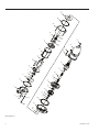
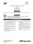
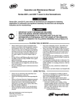
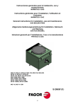
Form P6031
03524832
Edition 12
January 2011
Air and Gas Powered Starter
Series 150BMG
Installation and
Maintenance Information
Save These Instructions
Product Safety Information
Intended Use:
The 150BMG Series Air starters are intended for use in starting reciprocating internal combustion engines. These starters are designed
to be operated from a remote location after proper installation on the engine requiring starting.
For Additional information refer to Air Starters Product Safety Information Manual Form 45558624.
Manuals can be downloaded from www.ingersollrandproducts.com
Lubrication
Ingersoll Rand strongly emphasizes the importance of proper
lubrication for achieving top performance and maximum durability
with this starter. Either one of two lubrication systems is
recommended.
For typical starter installations where the cranking cycle is less than
10 seconds, we recommend an Ingersoll Rand No. HDL3 Lubricator
installed as shown in Dwg. TPC585. Use either diesel fuel or 10W
nondetergent motor oil for lubricating the starter.
If the cranking cycle is more than 10 seconds, we recommend the
Ingersoll Rand No. Lubricator NL-24-8 installed in the main air
supply line. Use a good quality 10W nondetergent oil and adjust the
lubricator to flow 1 to 3 drops per second.
NOTICE
When an HDL3 Lubricator is used, make certain that the oil supply line pressure is no greater than 5 psi. If there is pressure on
the line, the lubricator will continuously leak lubricant through
the starter and out of the exhaust.
Placing the Starter in Service
How to Order a Starter
MODEL CODING
Drive
Orientation Code
150 BM G E 21 RH 6- 0 2 0
Size Starter
Drive Housing
Exhaust
Type Starter
Gas Sealed
Gearing
Drive Housing
Inlet
Type Pinion
Rotation
(Dwg. TPD1732)
For specific models or special applications, contact your nearest Ingersoll-Rand Distributor or Ingersoll-Rand Engine Starting Systems,
Box 8000, Southern Pines, NC 28387 (910) 692-8700.
Installation
NOTICE
For maximum performance, read this manual prior to
installation or operation of Series 150BMG Starters.
General Information
1. This starter must be installed according to the instructions in this
manual.
2. Ingersoll-Rand recommends that on all vehicular installations and
on stationary engines subject to vibration, hoses of the specified
diameter be used instead of rigid pipe connections. Vehicle and
engine vibration will soon loosen rigid pipe connections, whereas
hoses will absorb the vibration, and connections will remain
tight.
3. When mounting a starter, make the hose connections at the
receiver and have the starter end of the hose handy for attaching
to the starter. Wherever possible, attach the air hoses to the
starter before mounting the starter on the flywheel housing.
There are two reasons for following this procedure:
a. After mounting the starter, it is often impossible to make hose
connections due to space limitations.
b. Once attached, the hoses carry some of the weight of the
starter, making it easier to complete the mounting.
2
4. Engine design often demands that the starter be mounted
underneath in extremely close quarters. Therefore, even though
two of the mounting bolt holes are easy to get at, the third
one is often difficult to reach. The tools usually needed in the
installation of a starter are a regular ratchet wrench, sockets,
universal joint, socket extension and a single or double-end
ratcheting box wrench.
5. The efficiency of a starter can be greatly impaired by an improper
hook-up. Hoses smaller than those recommended will reduce the
volume of air to the motor, and the use of reducers in the exhaust
port will restrict the exhaust and choke the motor. The use of tees
and elbows and the length of the supply line should be kept to
a minimum. In normal installations, hoses running from the air
tank to the starter should be No. 20 and fittings should be 1-1/4”.
Control hoses should be No. 4 and fittings should be 1/4”.
6. A leak in any of the connections means that the system will drain
overnight and will have to be repressurized the next morning
by using another vehicle or compressor. Make the connections
right the first time to avoid unnecessary costs and delays. On all
threaded connections throughout the system, use Ingersoll-Rand
No. SMB-441 Sealant, non-hardening No.2 Permatex,
Loctite®* Pipe Sealant or Perma-Lok® LH050**. Always run the air
supply line from the side or top of the receiver, never at or near
the bottom. Moisture will collect at the bottom of the receiver
03524832_ed12
causing corrosion and icing in cold weather. If either of these
conditions exist, the starter will not operate. After all connections
have been made, check each joint with a soap bubble test,
7. Installation of a “glad hand” for emergency repressurizing the
system is recommended. To keep the “glad hand” clean and free
of dirt, and to protect it from distortion, a second “glad hand”
closed by a pipe plug can be mated to it, or a glad hand protector
bracket can be used.
8. Whenever possible, always mount the starter so that the exhaust
port is downward This will help prevent any accumulation of
water in the starter motor.
9. For increased protection during extended shelf life, the motor
components of the starter have been coated with
Ingersoll Rand No. 50 Oil. This oil will be dispersed during the first
few cycles of the starter.
Relay Valve Location
Ingersoll-Rand recommends that the Relay Valve be mounted on the
air tank. As an alternate location, the Relay Valve can be mounted
on the starter. Mounting on the starter gives better control of the air
supply closer to the point of use and provides more starts per tank
of air. However, mounting on the starter adds overhung weight and
subjects the air supply lines to dynamic pressure at all times.
* Registered Trademark of Loctite Corporation
** Registered Trademark of Permabond Corporation
Orientation of the Air Starter
If the factory orientation will not fit your engine due to radial location
of the Drive Housing or location of the inlet and/or exhaust ports,
re-orient the starter as follows:
1. Refer to the dimension illustration and note that the drive
housing can be located in anyone of eighteen radial positions
relative to the gear case. The exhaust port (motor housing) can
be located in any one of four radial positions relative to the Gear
Case, and the air inlet (Motor Housing Cover) can be located in
any one of four radial positions relative to the exhaust port.
2. Study the engine mounting requirements, and determine the
required orientation of the Drive Housing relative to the Gear
Case. If the Drive Housing has to be reoriented, remove the
twelve Drive Housing Cap Screws and rotate the Drive Housing to
its required position.
NOTICE
Do not separate the Drive Housing from the Gear Case Cover.
Reinstall the Drive Housing Cap Screws and tighten them to 100 in-lb
(11 Nm) of torque.
3. When orienting the Drive Housing relative to the Gear Case,
determine if the exhaust port will be at the bottom and if the
inlet port will be favorably located for hose installation. If either
or both of these members must be reoriented, remove the four
Motor Housing Cover Cap Screws, and rotate the Motor Housing
and/or Motor Housing Cover to its desired position.
NOTICE
Do not separate these members from each other or from the
Gear Case. Reinstall the Motor Housing Cover Cap Screws and
alternately tighten them to 25 ft-lb (34 Nm) of torque.
Mounting the Air Starter
1. Study the piping diagram Dwg. TPC585.
2. The air receiver tank for a starter installation must meet
SAE J10B specifications or conform to ASME specifications. It
must have a working pressure capability equal to or greater than
the maximum pressure at which the starter will be operated.
3. When connecting the starter to a receiver tank that is already in
service, bleed off the air pressure by opening the drain valve.
WARNING
Bleed off the air pressure through a valve or petcock. Do not
remove a plug from the tank while the tank is still pressurized.
Drain off any water that has accumulated in the bottom of the
tank.
4. Using a 1-1/4” short nipple, install the SRV125 Starter Relay Valve
on the end of the receiver tank as shown in the piping diagram.
03524832_ed12
NOTICE
Make certain the connection is made to the inlet side of the Relay
Valve indicated by the word ‘IN” cast on the valve body.
5. Install the No. SMB-618 Starter Control Valve on the dash panel
(for vehicular installations) or some other appropriate panel (for
stationary installations).
6. Attach No. TA-STR-100 Starter Instruction Label to the control
panel adjacent to the Starter Control Valve.
7. Mount the No. 150BMP-1064 Air Pressure Gauge on or adjacent
to the control panel. It should be located where it is readily visible
to the operator of the Control Valve.
8. Connect the Starter Control Valve to the Relay Valve with 1/4”
hose. Install a Tee in this line with a short feeder hose to the
Pressure Gauge.
NOTICE
Make certain the hose is connected to the “SUPPLY” side of the
Starter Control Valve.
9. To determine the exact length of 1-1/4” air hose required, run a
piece of heavy-duty hose or some other flexible tubing of the
same diameter from the Relay Valve on the receiver to the Starter
location on the engine.
10. Attach the 1-1/4” air hose to the outlet side of the Relay Valve, and
run the hose through the frame to its final position at the starter
location.
11. At this point, determine if it is feasible or practical to attach the
hose to the starter before or after the starter is actually mounted.
In many cases, it may be necessary to attach the hose to the
starter before mounting.
12. If possible, liberally grease the teeth on the ring gear with a
good, sticky gear grease or motorcycle chain lube. This will help
promote the life of the ring gear and the Starter Pinion.
13. Place the starter into position, and mount it on the flywheel bell
housing. Tighten the mounting bolts to 100 ft-lb (136 Nm) of
torque.
14. If the exhaust is not to be piped away, install a No. 150BM-A674
Muffler or No. 150BM-A735 Road Splash Deflector in the exhaust
port on the Motor Housing of the Starter.
15. Pressurize the complete starting system and check every
connection with a soap bubble test. There must be no leaks.
Barring Over the Engine
Occasionally, for setting injectors and/or for timing purposes, it may
be desirable to bar over the engine in such a manner that any given
piston can be stopped at any given location. This is very easily done
with a 150BMG Starter.
3
1. Disconnect the 1/4” hose at the “OUT” port on the Drive Housing,
and plug the hole in the Drive Housing with a 1/4” pipe plug.
2. Remove the 3/8” pipe plug from the center of the Motor Housing
Cover.
3. Engage the Drive Pinion with the flywheel by applying a
minimum of 70 psig (4.8 bar/483kPa) to the “IN” port on the Drive
Housing.
4. Insert a 5/16” hexagonal wrench through the hole in the Motor
Housing Cover to engage the hexagonal recess at the rear of the
Rotor.
5. Manually, rotate the Rotor until the engine is cranked to its
desired position.
Gas Operated Starters
WARNING
When repairing a gas-operated starter or when converting a
starter from air operation to gas operation, it is necessary to use
Ingersoll-Rand No. MBA31 Plastic Gasket, as directed, and the
following procedures for assembly and testing must be explicitly
followed.
4
1. Apply a thin film of sealant to the Housing Cover End Plug and
the Lubricator Port Plug as they are assembled.
2. Plug the exhaust. Connect air line to the inlet, regulate the air
pressure to 40 psig (2.8 bar/280 kPa) and immerse the unit for
30 seconds in light oil, or non-flammable solvent. If there are
any bubbles, the unit is unfit for gas operation. Tighten where
necessary and/or apply sealant to area showing leak. Retest.
03524832_ed12
03524832_ed12
3.56
3.25
1 1/4 -11 1/2 NPT Inlet
1 1/4 -11 1/2 NPT
Exhaust
4 Capscrews
Motor Housing may be rotated
to any one of 4 Angular positions
to provide Engine Clearance
Cover
2.00
R 1.25
Motor
Housing
12.34
3.
4.
5.
6.
2.
1.
Performance Data @ 120 psi
108
146
ft/lbs
Nm
MAX TORQUE
Orientation Options
Motor Housing
Gear Case
4 @90º
4 @90º
21.3
2.46
MAX HP @ RPM
1740
Drive Housing
18 @ 20º
These Models available Gas Sealed. Identify with a “G” in the Model, Example: 150BMGE21RH-6
These Models have 4-Bolt Mounting Flange (Drive Housing 9BM-300-4)
This Model has SAE No. 1 Mounting Flange (Drive Housing 10BM-300-1)
Any previously published model not listed at right will require price and delivery quotation.
Model
“E” Ratio
Cover
4 @90º
Notes:
1. Starters should be installed on the Engine with the exhaust pointed down.
2. Use the set of control ports on the upper side of the Drive Housing.
(Only Drive Housings with two sets of Control Ports)
3. Drive Housing Orientation code is based on Position of mounting hole opposite the Pinion Opening.
4. Please read the instructions before attempting to reorient.
5. Starter wieght: 38lbs (17.5 kg)
6. Lubricator and Muffler Included.
Std Tolerances unless otherwise specified
.xx = ±.010
.xxx = ±.005
xº = ±.5º
3/8 -18 NPT Lube
connection
18.03
12 Capscrews
Drive Housing may be rotated
to any one of 18 Angular positions
to provide Engine Clearance
Drive
Housing
3.25
(3)
(3)
(3)
(4)
(4)
(3) (5)
4.44
13
8/10
150BME21LH-11
150BME21RH-6
150BMC21RH-39
150BMC22RH-38
150BME21LH-37
150BME22RH-5
10BM-299-19 A-3238
10BM-299-21 A-3233
12
6/8
11
12
6/8
11
12
6/8
Replace with 150BME21RH-6
Replace with 150BME22RH-5
Replace with 150BME21LH-11
11
10BM-299-21 A-3233
A-3242
8/10
DP
Pinion Data
Blank Size
150BME21RH-31
9BM-299-4
13
No. of Teeth
10BM-299-21 A-3233
11
6/8
10BM-299-22 A-3344
12
8/10
Price and Delivery must be confirmed on above models
10BM-299-22 A-3344
12
13
8/10
150BME22LH-8
A-3400
Facet
Normally Available Models
Left Hand or
Counter Clockwise
Rotation
120˚
72˚30’
150BME23RH-12
150BME24RH-19
9BM-299-9
IR
Drive Number
Ø 3.624
150BME12RH-13
Model
* PD for Lay Out Purpose
Gear Case
Ø 5.25
8.69
6.0
2.000
2.000
2.000
1.625
2.000
1.625
1.625
1.625
PD*
20º
20º
20º
20º
20º
20º
20º
20º
PA
(Dwg. TPA1441)
Right Hand or
Clockwise Rotation
Ø 4.718
120˚
R 2.359
150BMG Series Air and Gas Starters Dimensional Drawing
5
150BMG Series Air and Gas Starters Typical Installation
Starter control Valve
SMB-G6618
# 4 Hose (1/4”)
# 4 Hose (1/4”)
# 4 Hose (1/4”)
Air Pressure Gage
150BMP-1064L
JIC 37˚ Adapter
1/4 NPT
Check Valve
150BMP-1056
JIC 37˚ Adapter
1 1/2 NPT
Air Supply
Air
Receiver
Tank
See Recommended
Hose Size
1 1/2” NPT
HDL3 Luricator
Drain Valve
150BMP-1067
1/2 NPT
Note:
Use Seleant on all pipe connections.
SMB-441
For Gas Operation the exhaust outlet must be piped
away to a safe location.
Ingersoll Rand Part Number
For Natural Gas Operation, Piped Exhaust must be
used and Drive Housing vent plug replaced with
suitable hose which connects into piped exhaust
system.
The performance of the Starter is dependent on the pressure at the inlet of the starter.
This pressure is effected by the pressure drop between the Air Receiver Tank and the Starter.
The most significant pressure drops will occur in fittings (Valves, Tees, Elbows, etc.)
The next significant source of pressure drop is the hose. The following table provides
recommended hose and Starter Relay Valves (SRV) sizes for typical one starter installations.
Systems with many fittings or long hose should be analyzed and sized individually.
(Dwg. TPC585)
Hose Length
Starter
3BM, 5BM
SS175
150BM/LF, SS350
0-30’
0-30’
0-10’
10-30’
SS810, 815, 825, 850
ST750, 799
0-50’
For Air Applications a Muffler or Splash Guard
Deflector must be used.
Hose Size
SRV Size
# 12 (3/4 “)
# 12 (3/4 “)
# 16 (1 “)
# 20 (1 1/4“)
# 24 (1 1/2“)
SRV 100
SRV 100
SRV 100
SRV 125
SRV 150
Series 150BM and 150BMG Performance Curves
120
25
1200
20
900
15
600
Flow (SCFM)
100
60
Power (HP)
Torque (lb-ft)
80
40
10
300
5
0
20
0
0
(Dwg. TPC611)
6
500
1000
1500
Speed (RPM)
2000
2500
3000
03524832_ed12
03524832_ed12
2
1
10
7
6
5
2
8
9
40
55
11
12
13
21
16
18A
18
15
19A
20
19
14
39
55
38
36
37
22
35
56
34
33
24
23
53
52
32
Air Strainer
51
31
27
54
30
150BMG Series Air and Gas Starters Sectional View
(Dwg. TPA61-7)
7
30
19A
18A
5
15
2
6
56
16
2
18
19
1
34
21
55
33
22
7
9
20
8
32
10
31
13
40
23
11
24
37
27
36
39
35
12
14
55
38
150BMG Series Air and Gas Starters Exploded View
(Dwg. TPA683-2)
8
03524832_ed12
150BMG Series Air and Gas Starters Parts List
Item
Part Description
1
2
*
*
Motor Housing Cover Assembly
Housing Cover End Plug (3)
Nameplate
Nameplate Screw (3)
5
Motor Housing Cover Cap Screw (4)
6
Part
Number
150BMP-A102A
HSPPS3
150BM-301
R4K-302
Item
32
107-25
Part Description
Drive Shaft
for Model E22RH5-020
for Models C21RH-6, C21LH-11,
C21RH-16, C21RH-17,
C21RH-31, C21LH-32, E21RH6-20
Cover Cap Screw Washer (4)
D02-504
†7
Motor Housing Cover Gasket
150LF-283
‡ 33
Drive Shaft Collar
†8
Rear Rotor Bearing
R3H-24
† 34
Drive Shaft Front Bearing
G57-729
150LF-12A
150BM-3
10BM-98
10BM-42-5
10BM-40
10BM-37
10BM-25
10BM-399
R2-227
† 35
36
Rotor Pinion Retainer
Rotor Pinion
for “C” Models
for “E” Models
Front Rotor Bearing
Gear Case Gasket
Front End Plate
Rotor
Air Strainer Assembly
Air Strainer Cap
Air Strainer Plug
Air Strainer Screen
Gasket (2)
Gasket
Air Strainer Nipple (1-1/4” x 2-1/2”)
Mounting Adapter
Mounting Adapter
Mounting Adapter
Road Splash Deflector Assembly
Muffler Assembly
Plastic Gasket
Pipe Sealant
Tune-up Kit
(includes illustrated parts 7, 8, 9, 13,
16, 18, 19A,20, 22, 30, 34, 35, 37,
and 38)
†9
10
11
12
† 13
14
15
† 16
† 18
18A
19
† 19A
† 20
21
† 22
23
24
27
† ‡ 30
‡ 31
Rear Rotor Bearing Retainer
Rear End Plate
Cylinder
Cylinder Dowel
Vane Packet (set of 5 Vanes)
Motor Housing
Gear Case Assembly
Bearing Ejecting Washer
Drive Shaft Rear Bearing
Plug
Drive Gear
for C models
for E models
Drive Gear Thrust Washer
Drive Gear Key
Gear Case Cover Assembly
for Model C12RH-13
for all other models
Drive Shaft Grease Seal
Drive Housing Cap Screw
Lock Washer (12)
Drive Housing Cap Screw (12)
Drive Housing Assembly
Drive Housing Bearing
Starter Drive
10BMC-9
150BME-9
10BM-15
10BM-610
10BM-378
10BM-478
150BMP-271
--10BM-67
10BM-744
9BM-A300-H2
ML50K-318
10BM-299-21
for Models BM21LH-11 and BMG21LH-11 10BM-299-19
for Models BM21RH-5 and BMG22RH-5
10BM-299-22
for Models BM21RH-6 and BMG21RH-6
Part Number
10BM-108
10BM-8
E21LH11-020
† 37
† 38
39
40
# 51
52
53
54
55
56
*
*
*
*
*
*
*
*
*
10BM-30
T02-33
10BM-69
101BMPD-17
150BME-17
10BM-24
150LF-284
150LF-11A
10BMP-53
K4U-A267AT
K4U-286AT
22SR-165
K4U-61AT
150BMP-283
150BMP-284
KKM-286
9BM-B212-5/8
9BM-B212-1
10BM-CU212-1/2
150BM-A735
150BM-A674
SMB-431
SM-441
150BM-TK2
* Not Illustrated
† Indicates Tune-up Kit part.
‡ For every C model listed, there is a comparable E model. With the exception of the Drive Gear (19) and Rotor Pinion (36), comparable C and E
models are identical.
# Recommended on applications where air or gas could be contaminated.
03524832_ed12
9
Maintenance Section
WARNING
Always wear eye protection when operating or performing any maintenance on this Starter.
Always turn off the air or Gas supply and disconnect the air supply hose before installing, removing or adjusting any accessory on this
Starter or before performing any maintenance on this Starter.
Note: When reading the instructions, refer to exploded diagrams in parts Information Section when applicable.
Lubrication
Each time a Model 150BMG Starter is disassembled for
maintenance or repair, lubricate the starter as follows:
1. Lubricate all open bearing and gear teeth with a liberal coat of
Ingersoll Rand No. 130 Grease.
2. Cover the bore of the Motor Housing Cover (1) with
Ingersoll Rand No. 130 Grease.
3. Apply a thin film of Ingersoll Rand No. 130 Grease to the Drive
Shaft (32) and the bore of the Drive Shaft Front Bearing (34), Drive
Shaft Collar (33) and Drive Gear (19).
Disassembly of the Starter
General Instructions
1. Do not disassemble the starter any further than necessary to
replace worn or damaged parts.
2. When grasping a part in a vise, always use leather covered or
copper-covered vise jaws to protect the surface of the part and
help prevent distortion. This is particularly true of threaded
members.
3. Do not remove any part which is a press fit in or on a
subassembly unless the removal of that part is necessary for
replacement or repairs.
4. Always have a complete set of seals and O-rings on hand before
starting any overhaul of a Model 150BMG Starter. Never reuse old
seals or gaskets.
5. Always mark adjacent parts on the Motor Housing Cover (1),
Motor Housing (14), Gear Case (15) and Drive Housing (27) so
these members can be located in the same relative position when
the starter is reassembled.
6. Never wash the Starter Drive (31) in a solvent.
7. Do not press any needle bearing from a part unless you have a
new needle bearing on hand for installation. Needle bearings are
always damaged during the removal process.
Disassembly of the Motor
1.
2.
3.
4.
Unscrew the Motor Housing Cover Cap Screws (5).
Pull the Motor Housing Cover (1) from the Motor Housing (14).
Slide the Motor Housing from the motor.
Grasp the rear end of the motor and pull the entire assembly
away from the Gear Case (15).
5. Position the motor assembly vertically, grasping the Rotor Pinion
(36) in leather-covered or copper-covered vise jaws.
6. Remove the Rear Rotor Bearing Retainer (9).
7. The Rear Rotor Bearing (8) is press fit on the rotor shaft. Use a
bearing puller to remove it.
8. Lift off the Rear End Plate (10) and Cylinder (11) and remove the
Vanes (13) from the slots in the Rotor.
9. Reposition the Rotor vertically, pinion end up, and grasp the
short hub in leather-covered or copper-covered vise jaws.
10. Remove the Rotor Pinion Retainer (35) and lift off the
Rotor Pinion (36).
11. Support the Front End Plate (39) as close to the Rotor as possible,
and press the Rotor from the Front Rotor Bearing (37). Do not let
the Rotor fall when it is pressed free.
Disassembly of the Gear Case
1. Set the gear case and drive housing unit upright on the
workbench with the Drive Housing (27) upward.
10
4. Wipe a thin film of Ingersoll Rand No. 130 Grease on the Drive
Gear Thrust Washer (19A).
5. Apply about 8 ounces of Ingersoll Rand No. 130 Grease to the
assembled Drive Gear (19) and a uniform coat to the
Drive Shaft (32) working the grease between all gear teeth,
splines and bearing surfaces.
6. Wipe a thin film of Ingersoll Rand No. 130 Grease in the bore of
the Drive Housing (27).
2. Remove the Drive Housing Cap Screws (24) and Drive Housing
Cap Screw Lock Washers (23) and lift off the Drive Housing, Drive
Gear and Starter Drive.
3. Thread a 5/16”-18 thread cap screw into the tapped hole in the
Bearing Ejecting Washer (16) and continue to turn it until the
Drive Shaft Rear Bearing (18) is jacked from the Gear Case (15).
Disassembly of the Drive Housing
1. With the Drive Housing unit lying on the workbench, grasp the
Drive Gear (19) and pull the assembled Drive Shaft (32) from the
Starter Drive (31).
2. If the Drive Gear must be removed from the Drive Shaft, support
the Drive Gear on the table of an arbor press, and press the Drive
Shaft from the Drive Gear. Remove the Drive Gear Key (20).
3. Stand the Drive Shaft assembly, bearing end up, in a sleeve that
contacts the Drive Shaft Collar (33), and press the Drive Shaft
from the bore of the Drive Shaft Front Bearing (34).
4. Position the Drive Housing (27) vertically, grasping the Gear Case
Cover (21) in leather-covered or copper-covered vise jaws. Tap
the underside of the drive housing mounting flange with a soft
hammer to dislodge the Drive Housing from the Gear Case Cover.
Lift off the Drive Housing. The Starter Drive will probably remain
with the Drive Housing; make certain that it does not fall on the
floor.
NOTICE
Do not remove the Drive Shaft Grease Seal (22) from the Gear
Case Cover unless it is absolutely necessary and you have a new
Seal on hand. If the Seal must be removed, press it from the Gear
Case Cover.
5. Do not remove the Drive Housing Bearing (30) from the Drive
Housing unless you have a new Bushing on hand. If the Bearing
must be removed, press it from the Drive Housing.
Cleaning the Parts
Once the Starter has been disassembled, clean all parts for
inspection.
1. Wipe all dirt, grease, etc. from the Starter Drive and sealed
bearings.
NOTICE
Do not wash these parts in kerosene or other solvent, as this will
dilute and contaminate any sealed-in lifetime lubricant.
2. Wash all parts except the Start Drive or any sealed bearing in
clean kerosene or other solvent. Dry the parts with compressed
air.
03524832_ed12
Inspection of Parts
1. Discard all O-rings and gaskets. These should not be reused.
2. Check all grease seals. If they appear worn or distorted, remove
them from their parent member and discard.
NOTICE
Discard any grease seal that was removed during disassembly
of the starter.
Assembly
General Instructions
Assembly of Motor
1. Always press on the inner ring of a ball-type bearing when
installing the bearing on a shaft.
2. Always press on the outer ring of a ball-type bearing when
pressing the bearing into a bearing recess.
3. Whenever grasping a starter or part in a vise, always use
leather-covered or copper-covered vise jaws. Take extra care with
threaded parts or housings.
4. Always clean every part and wipe every part with a thin film of
Ingersoll Rand No. 50 Oil before installation.
5. Check every bearing for roughness. If an open bearing must
be cleaned, wash it thoroughly in a clean, suitable, cleaning
solution and dry with a clean cloth. Sealed or shielded bearings
should never be cleaned. Work Ingersoll Rand No. 130 Grease
thoroughly into every open bearing before installation.
6. Apply a film of o-ring lubricant to all o-rings before final
assembly.
7. Lubricate all open bearing and gear teeth with a liberal coat of
Ingersoll Rand No. 130 Grease. Lubricate Starter Drive Housing
Bearing (30) and gear teeth with a liberal coat of Ingersoll Rand
No. 130 Grease. Work about 3 cc into the teeth of the Drive Gear.
8. Lubricate the Gear Case and Gear Case components with
Ingersoll Rand No. 130 Grease.
9. When assembling the motor always use new O-rings.
10. Before installing O-rings, coat liberally with O-ring lubricant. After
the O-ring is installed, coat the O-ring again with o-ring lubricant
and apply O-ring lubricant to O-ring grooves.
11. The Cylinder Dowel (12) maintains the alignment of the Motor
Housing Cover (1), Front End Plate (39), Cylinder (11) and Rear
End Plate (10). The end of the Dowel fits into a shallow hole in the
face of the Motor Housing Cover. It is important that the end of
the Dowel is in the hole and remains there during assembly.
12. Unless otherwise noted, always press on the stamped end of a
needle bearing when installing the needle bearing in a recess.
Use a bearing inserting tool similar to the one shown in
Dwg. TPD786.
Needle Bearing inserting Tool
Shoulder to
Regulate Depth
3. Check all needle bearings. Discard any needle bearing that was
pressed from a parent member during disassembly of the starter.
Remove and discard any other needle bearing that appears worn,
distorted, has loose needles or does not run freely.
4. Check all ball bearings. These should run freely without any rough
spots or binding. Discard any bearing that gives any indication
of wear. Check the Vanes for separation, chipping, wear, checks,
etc. See that they fit freely in the vane slots in the Rotor. We
recommend that a complete new set of Vanes be installed
whenever the Starter is disassembled.
15°
Pilot to fit I.D. of Bearing.
Length of Pilot to be
approximately 1/8” less than
length of Bearing
1. Position the Rotor (40) vertically, splined end down.
2. Place the Rear End Plate (10), crescent grooved side first, onto the
hub of the Rotor.
NOTICE
Make sure that all notches and ports are in alignment.
Refer to Dwg. TPA683-2.
3. Install the Rear Rotor Bearing (8) onto the hub of the Rotor until it
contacts the Rear End Plate. Make certain the End Plate does not
bind against the Rotor.
4. Install the Rear Rotor Bearing Retainer (9) in the groove on the
hub of the Rotor.
5. Grasp the Motor Housing Cover (1), motor bore face upward,
in copper-covered or leather-covered vise jaws. Swivel the vise
so that the air inlet is facing you. Cover the bore of the bearing
recess with a thin film of Ingersoll Rand No. 130 Grease.
6. Check the nameplate on the Starter to determine whether you
have an “LH” model or “RH” model.
For “LH” models: While facing the air inlet on the Motor Housing
Cover, insert the Cylinder Dowel (12) in the dowel hole on the
right of the inlet.
For “RH” models: While facing the air inlet on the Motor Housing
Cover, insert the Cylinder Dowel (12) in the dowel hole on the left
of the inlet.
NOTICE
Make certain the Cylinder Dowel is installed in the proper dowel
hole. If you put it in the wrong dowel hole, the motor will rotate
in the wrong direction.
7. Place the Motor Housing Gasket (7) in the bore of the Motor
Housing Cover.
NOTICE
Make sure that the Motor Housing Gasket is installed with the
Cylinder Dowel hole positioned upward and properly oriented
relative to the Cylinder Dowel. The Cylinder Dowel hole in the
Gasket is the hole which is centered between the two angled
ports in the Gasket. Refer to Dwg. TPA683-2.
8. Place the assembled End Plate and Rotor into the Motor Housing
Cover that the Cylinder Dowel passes through the dowel hole in
the End Plate, and so that the air port in the End Plate aligns with
the port in the Gasket and Motor Housing Cover.
9. Place the Cylinder (11) down over the Rotor so that the Cylinder
Dowel passes through the dowel hole in the Cylinder and so that
the air port in the Cylinder is aligned with the air port in the Rear
End Plate, Gasket, and Motor Housing Cover.
10. Place the Motor Housing (14) down over the Cylinder making
certain that the prick punch marks on the Motor Housing Cover
and Motor Housing are aligned.
11. Liberally coat each Vane (13) with Ingersoll Rand No. 50 Oil and
insert a Vane into each slot in the Rotor. Make certain the straight
edge of each Vane faces the Cylinder.
(Dwg. TPD786)
03524832_ed12
11
12. Set the Front End Plate (39), crescent grooved side first, onto the
Cylinder so that the Cylinder Dowel passes through the dowel
hole in the End Plate. Make sure that all notches and ports are in
alignment.
13. Install the Front Rotor Bearing (37) onto the splined shaft of the
Rotor until it seats against the Front End Plate. Do not bind the
End Plate against the Rotor.
14. Slide the Rotor Pinion (36) onto the rotor shaft.
15. Install the Rotor Pinion Retainer (35) in the groove on the rotor
shaft so that the concave side of the Retainer faces the Rotor
Pinion.
16. Apply a light coat of Ingersoll Rand No. 130 Grease to the Gear
Case Gasket (38) and place the Gasket in the motor bore of the
Gear Case.
17. Set the Gear Case on the assembled motor, making certain the
prick punch marks on the Gear Case are aligned with those on
the Motor Housing.
18. Turn the entire assembly over so that the Motor Housing Cover is
upward. Make sure that the Cylinder Dowel remains seated in the
shallow hole in the face of the Motor Housing Cover.
19. Install the Motor Housing Cover Cap Screws (5) and Lock Washers
(6). Tighten the Cap Screws alternately to 25 ft-lb (34 Nm) of
torque.
Assembly of Drive Gear
1. If the Drive Shaft Grease Seal (22) was removed from the Gear
Case Cover (21), press in a new Seal so that the inner lips of the
Seal face the bearing recess for the Drive Shaft Front Bearing (34).
2. Apply a thin film of Ingersoll Rand No. 130 Grease to the Drive
Shaft (32) and the bore of the Drive Shaft Front Bearing, Drive
Shaft Collar (34), and Drive Gear (19).
3. Press the Drive Shaft Collar, beveled end first, onto the keyway
end of the Drive Shaft until it seats against the shoulder of the
shaft.
4. Press the Drive Shaft Front Bearing onto the keyway end of the
Drive Shaft until it seats against the Drive Shaft Collar. Pack the
Bearing with Ingersoll Rand No. 130 Grease.
5. Install the Drive Gear Key (20) in the keyway on the Drive Shaft.
6. Press the Drive Gear (19), long hub first, on the Drive Shaft until it
contacts the Drive Shaft Front Bearing.
Assembly of Gear Case
1. Set the assembled motor and Gear Case (15) on end with the
Gear Case upward.
2. Place the Bearing Ejecting Washer (16) in the bearing recess.
3. Using a needle bearing inserting tool, press the Drive Shaft
Rear Bearing (18), unstamped end first, into the bearing recess
until the trailing face of the Bearing is flush with the face of the
bearing recess. Refer to Dwg. TPD786.
Work some Ingersoll Rand No. 130 Grease between the-rollers of
the Bearing.
4. Wipe a thin film Ingersoll Rand No. 130 Grease on the Drive
Gear Thrust Washer (19A), and place the Washer on the lip of the
bearing recess in the Gear Case.
5. Apply about 8 ounces of Ingersoll Rand No. 130 Grease to the
assembled Drive Gear (19) and a uniform coat of
Ingersoll Rand No. 130 Grease to the Drive Shaft (32), making
certain to work the grease between all the gear teeth, splines and
bearing surfaces.
6. Insert the assembled Drive Gear and Shaft, short hub end first,
into the Gear Case so that the short hub enters the Drive Rear
Bearing.
7. Slide the assembled Gear Case Cover, bearing recess first, down
over the Drive Shaft until it seats against the Gear Case.
NOTICE
Check the inner lip of the Drive Shaft Grease Seal to make certain
that it did not fold outward toward the end of the Drive Shaft. If
it did fold outward, you must reinstall the Gear Case Cover using
a fine pointed instrument to roll the lip of the seal the proper
direction.
Assembly of Drive Housing
1. If the Drive Housing Bearing (30) was removed, stand the Drive
Housing (27) upright and press a new Drive Housing Bearing,
unstamped end first, into the Drive Housing until the unstamped
end of the Bearing is flush with the inside face of the Drive
Housing boss. Work some Ingersoll Rand No. 130 Grease in the
Bearing.
NOTICE
Do not clean the Starter Drive (31) with solvent. If Starter Drive
appears dry, apply Ingersoll Rand No. 130 Grease to the threads
under the pinion.
2. Apply a thin film of Ingersoll Rand No. 130 Grease to the surface
of the Drive Shaft (32).
3. Place the Starter Drive on the Drive Shaft.
4. Place the Drive Housing over the Drive onto the Gear Case Cover
(21). Rotate the Drive Housing into the required orientation as
indicated by the punch marks. At the same time, align the Cap
Screw holes in the Gear Case Cover and Housing.
5. Install the Drive Housing Cap Screws (23) and Lock Washers (24)
and tighten the Cap Screws to 100 in-lb (11 Nm) of torque.
Testing the Starter
1. Turn the pinion by hand in the direction of Starter rotation. The
pinion should advance smoothly and easily to the stop.
2. Turn the pinion opposite the direction of Starter rotation. The
gearing and motor should rotate freely with no binding.
3. Attach an air hose to the inlet and operate the motor slowly to
see that it functions properly and that the drive pinion rotates in
the proper direction. If the direction of rotation is incorrect, the
motor was improperly assembled.
12
4. The chambers on the pinion teeth should be on the following
side of the teeth.
03524832_ed12
Troubleshooting Guide
Trouble
Probable Cause
No air supply
Motor will not
run
Solution
Check for blockage or damage to air supply lines or tank.
Damaged motor assembly
Inspect Motor Assembly and power train and repair or replace if necessary.
Foreign material in motor and/or piping
Remove Motor Assembly and/or piping and remove blockage.
Blocked exhaust system
Remove Housing Exhaust Cover (1) and check for blockage.
Defective Control Valve or Relay Valve
Replace Control Valve or Relay Valve.
Low air pressure to Starter
Check air supply.
Restricted air supply line.
Check for blockage or damage to air lines.
Relay Valve malfunctioning
Clean or replace lines or Relay Valve. Lube Relay Valve.
Exhaust flow restricted
Check for blocked or damaged piping. Clean or replace piping. Check for dirt
or foreign material and clean or remove. Check for ice build-up. Melt ice and
reduce moisture build-up to Starter.
Worn motor parts
Remove the motor from the Motor Housing (14) and disassemble the
motor. Examine all parts and replace any that are worn or damaged. Use the
following guidelines for determining unserviceable parts:
1. Vanes (13): Install a new set of Vanes if any Vane is cracked, checked or
worn.
Loss of Power
2. Rotor Bearings (8) or (37): Replace if any roughness or looseness is
apparent.
3. Rotor (40): Replace if there are any cracks or deep scoring.
4. Cylinder (11): Replace if there are any cracks or deep scoring.
5. End Plates (10) or (39): Clean up scoring by rubbing it with emery cloth
placed on a flat surface.
Lack of air to starter
Check for clogged or damaged air line between relay valve and starter.
Check relay valve to determine if it is functioning properly. Check air tank.
Parts and Maintenance
NOTICE
The use of other than genuine Ingersoll Rand replacement parts may result in safety hazards, decreased starter performance, and increased
maintenance, and may invalidate all warranties.
Ingersoll Rand is not responsible for customer modification of starters for applications on which Ingersoll Rand was not consulted.
Repairs should be made only by authorized trained personnel. Consult your nearest Ingersoll Rand Authorized Service center.
When the life of the tool has expired, it is recommended that the starter be disassembled, degreased and parts be separated by material so that
they can be recycled.
Manuals can be downloaded from www.ingersollrandproducts.com
Refer all communications to the nearest Ingersoll Rand Office or Distributor.
03524832_ed12
13
Notes:
Notes:
www.ingersollrandproducts.com
© 2011 Ingersoll Rand