Download V806 取扱説明書
Transcript
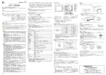
3134NB0 モニタッチ V806 をお買い上げいただき、誠にありがとうございます。 はじめに、ご希望どおりの商品であるかをご確認ください。 取り扱いにつきましては、この取扱説明書および『V806 シリーズ ハード仕様書』を十分ご理解の 上ご使用ください。 本書:1 部、取付金具:4 個、USB 固定用インシュロック:1 個 型式 1 画面サイズ 2 機能仕様 1 2 3 4 5 3 デバイス 仕様 4 電源仕様 06 i 5.7 インチ LAN ポートあり SRAM 512KByte なし LAN ポートなし SRAM 128KByte T TFT カラー LCD(QVGA 65,536 色) C TFT カラー LCD(QVGA 65,536 色) M TFT モノクロ LCD(QVGA モノクロ 16 階調) D DC24V(CE/UL/cUL 対応品) オプションユニット「DUN-10」/「CUN-xx」 ユニット N 専用 5 コネクタ (CN5) 仕様 なし オプションユニット「DU-10」/「CU-xx」専用 50.8 4 6.0 パネルカット穴 ○ 液晶の特性上、微少な斑点(黒点、輝点)が生じることがあります。 これは、製品の不良・故障ではありません。あらかじめご了承ください。 5 6 CN5 V806 は、UL/c-UL 認定品です。(File No. : E313548 (UL508)) 以下の 2 つの規格に適合しています。 ・ UL508 工業用制御装置 ・ CSA-C22.2 No. 142-M1987 工業用制御装置 U-B 1 2 F2 3 MJ2 LAN 14 9 10 11 電源ケーブル AWG14 - AWG16、定格温度 60℃、銅線使用 ピン No. DC24V 1ms 以内 消費電力(最大定格) 15W 以下 18A 以下、2ms 以内(DC24V 入力) 耐電圧 DC 外部端子と FG 間:AC500V、1 分間 0℃~+ 50℃ - 10℃~+ 60℃ 使用周囲湿度 85% RH 以下(ただし、結露なきこと、最大湿球温度 39℃以下 *1 保存周囲湿度 85% RH 以下(ただし、結露なきこと、最大湿球温度 39℃以下 *1 使用高度 標高 2000m 以下 *1 *2 MJ2 *1 ピン No. 1 *1 ) 腐食性ガスがなく、じんあいがひどくないこと、および導電性のじんあいがない こと 耐振動 振動周波数:10 ~ 150Hz、加速度:9.8m/s2(1.0G) 片振幅:0.075mm、X,Y,Z:3 方向 各 1 時間 耐衝撃 パルス波形:正弦半波 ピーク加速度:147m/s2(15G)、X,Y,Z:3 方向、各 6 回 耐ノイズ 1000Vp-p(パルス幅 1 μ s、立ち上がり時間:1ns) 2 *1 接地 D 種接地(第 3 種接地)、FG/SG 分離 構造 保護構造:フロントパネル:IP65 準拠(防水パッキン使用時) リヤーケース :IP20 準拠 形状 :一体形 取付方法:パネル埋込取付 板金板厚:1.5 ~ 5mm *4 7 RD RS-232C 受信データ 8 SD RS-232C 送信データ 感電の恐れがあります。電源ケーブルの配線は電源 OFF 状態で行ってください。 電源ケーブルの配線 信号名 +SD スライドスイッチ 上 RS-422 送信 データ (+) 下 -RD/-SD RS-485 データ (-) 4 5 87654321 内容 6 7 *1 8 *1 上 RS-422 送信 データ (-) +5V 外部供給 +5V Max. 150 mA *2 上・下 SG シグナルグラウンド 上・下 下 RD RS-232C 受信 データ 上 +RD RS-422 受信 データ (+) 下 SD RS-232C 送信 データ 上 -RD RS-422 受信 データ (-) 下 外形寸法 WxHxD 182.5 × 138.8 × 50.8 mm 174.0 - 0 × 131.0 - 0 材質 PC/ABS + 0.5 mm *1 故障の原因となりますので、湿球温度は 39℃以下でご使用ください。 *2 V806 シリーズに装着するオプションユニット、通信ユニット、取付角度により、使用周囲温度の 制限が異なります。詳しくは別途『V806 シリーズ ハード仕様書』を参照してください。 *3 本製品を使用した環境における導電性物質の発生度合を示す指標です。 「汚染度 2」は、非導電性の汚染のみが発生する状況を示します。ただし、凝結によって一時的な 導電が起こりうる環境です。 *4 板金板厚が仕様範囲内であっても、板金の材質や大きさによってはパネル自体が反る場合があり ます。取り付け強度が保てるパネルをご使用ください。 締め付けトルク M3.5 7.1 inch-lbf(0.8 N・m) 24VDC 電源 DC24V ± 10% アース FG ○ 電源は許容電源電圧変動範囲(DC24V ± 10%)内で使 用してください。 ○ 線間及び大地間ともノイズの少ない電源を使用してください。 ○ 電源線は電圧降下を小さくするために、できるだけ太い線を使用してください。 ○ 電源線は高電圧、大電流のケーブルとは近づけないように十分に離してください。 ○ 端子台には必ず電源端子カバーを取り付けてください。 ○ アースは専用接地にしてください。 ○ 接地用のケーブルには公称断面積 2mm2 以上のものを使用してください。 ○ 接地点は本体の近くにし、接地線の距離を短くしてください。 専用接地(最良) V806 本体 他の機器 共用接地(良) V806 本体 他の機器 わたり接地(禁止) V806 本体 他の機器 D 種接地 D 種接地 上側 下側 コイン型リチウム電池について SRAM ユーザメモリ領域(不揮発性メモリ $L、$LD やサンプリングデータの格納など)と内蔵時計 のバックアップ用の電池です。 工場出荷時、電池ケーブルは接続されていません。 Ethernet(100BASE-TX、10BASE-T)接続をするためのポートです。 仕様: IEEE802.3(u) 準拠、UDP/IP および TCP/IP 対応 ・ MJ1/MJ2 および LAN コネクタは共に 8 ピンモジュラージャックです。銘板を確 認し、誤挿入しないように注意してください。 ・ LAN ポートに接続する際、過電圧を持ち合わせている周辺機器との接続は避け てください。 電池の仕様、交換方法、および使用済電池の破棄方法について、詳しくは別途『V806 シリーズ ハー ド仕様書』を参照してください。 LAN コネクタ、LAN ケーブル等について、詳しくは別途『V806 シリーズ ハード仕様書』を参照し てください。 USB ポート(USB Ver. 1.1) A(マスター) タイプ 用途 B(スレーブ) ・USB プリンタ(ESPON PM プリンタ)接続 ・USB-CFREC 接続 ・パソコン接続(画面データ転送) ・PictBridge プリンタ接続 USB ポートの使い方、ケーブルの固定方法等について、詳しくは別途『V806 シリーズ ハード仕様書』 を参照してください。 ディップスイッチ ディップスイッチの設定は以下のとおりです。(下図:工場出荷時の状態) ディップスイッチを設定する際は、本体電源を OFF してから行ってください。 No. 1 MJ1 終端抵抗 2 2 MJ2 終端抵抗 3 3 MJ2 終端抵抗 4 CF 自動アップロード 4 OFF 1 ( 拡大図 ) 内容 設定内容について、詳しくは別途『V806 シリーズ ハード仕様書』を参照してください。 50600000 ネジサイズ DC24V 仕様 V806 シリーズは、必ず接地をしてください。 (接地工事は D 種接地、接地抵抗 100 Ω以下) スライド スイッチ *1 スライドスイッチで信号を切り替えます。 工場出荷時は“上側”です。 上側 : RS-232C/RS-485 (2 線式 ) 下側 : RS-422 (4 線式 ) *2 外部供給(+5V)は、オプションユニット装着時、 未装着時で、値が変わります。詳しくは別途『V8 06 シリーズ ハード仕様書』を参照してください。 ○ 電源ケーブルは本体背面の端子に接続します。 ○ 電源を配線する場合の端子ネジの締め付けは下記値で 行ってください。 アースの配線 -SD LAN コネクタ(LAN) V806i のみ パネルカット寸法 + 0.5 シグナルグラウンド 電源ケーブルの配線と接地について +RD/+SD RS-485 データ (+) 3 IEC61000-4-2 に準拠、接触 6kV、気中 8kV 2 約 740g SG 6 ) 使用雰囲気 自然空冷 外部供給+ 5V MAX 150mA * 外部機器とシリアル通信(RS-232C/RS-485 または RS-422)接続するためのコネクタです。 モジュラージャックのピン配置は以下のとおりです。 保存周囲温度 質量 +5V 表示面 裏面 モジュラージャック(MJ2) 使用周囲温度 冷却方式 -RD/-SD RS-485 データ (-) 4 DC500V、10M Ω以上 *3 2 3 絶縁抵抗 汚染度 内容 +RD/+SD RS-485 データ (+) * 外部供給(+5V)は、オプションユニット装着時、未装着時で、値が変わります。詳しくは別 途『V806 シリーズ ハード仕様書』を参照してください。 突入電流 耐静電気放電 信号名 1 取付角度は 0°~ 135°の範囲内で設置してください。 ただし、通信ユニット装着時は、通信ユニットおよび使用周囲温度 によって取付角度が異なります。 詳しくは別途『V806 シリーズ ハード仕様書』を参照してください。 面 示 許容瞬時停電時間 17.8 3. 防水パッキンは、板金パネルと V806 の間にしっかりと挟んで取り付けてください。 外部機器とシリアル通信(RS-232C/RS-485)接続するため、または画面転送するためのコネクタです。 5 DC24V ± 10% .0 取付角度 87654321 DC24V 10.5 18 V806 本体 FG モジュラージャック(MJ1) UL508 電圧許容範囲 (単位:mm) 板金パネル + 仕様 定格電圧 取付金具寸法 24VDC CE マーキング EN61000-6-2、EN61000-6-4 UL/cUL 取付穴 取付穴 表 対応規格 F4 F5 取付金具 単位 : mm 6. ディップスイッチ 11. LAN コネクタ(LAN) 7. スライドスイッチ 12. USB-B コネクタ(U-B) 8. 電源入力端子台 13. USB-A コネクタ(U-A) 9. モジュラージャック(MJ1)14. USB ケーブル固定穴 10. モジュラージャック(MJ2)15. 取付金具穴 ディスプレイ POWER ランプ(POWER) *1 ファンクションスイッチ オプションユニット用 コネクタ(CN5)*2 5. 電池ホルダ MJ1 機種 15 15 1. 2. 3. 4. 一般仕様 Y = 131.0 +0.5 -0 12 13 *1 電源が供給されている状態で点灯(緑) 。バックライト異常時に点滅。 *2 V8 の型式によって、対応オプションユニットが異なります。 「N」あり : オプションユニット「DUN-10」/「CUN-xx」対応 「N」なし : オプションユニット「DU-10」/「CU-xx」対応 ○ V806 シリーズは、EMC 指令に適合した製品です。 ○ EN61000-6-2、EN61000-6-4 に適合しています。 ○ V806 シリーズは「Class A」工業用環境商品です。住宅環境で使用する場合、電波妨害の原因とな る可能性があるため、電波妨害に対する適切な対策が必要となります。 項目 F3 2. 付属の取付金具(取付金具の数:4 個)を V806 の取付穴に挿入し、締め付けネジで V806 を固定 します。(締め付けトルク:0.5 ~ 0.7N・m) 締め付けトルク 7.1 inch-lbf(0.8 N・m) EM U-A 422 MJ1 ○ モニタッチの背面部分はエンクロージャとして認定されていません。モニタッチは機器に組み込み、 機器全体として規格に適合するエンクロージャを構成してください。 ○ モニタッチは室内専用機としてご使用ください。 ○ エンクロージャのタイプはタイプ 1 が適合するような平面上に取り付けてください。 ○ 電源を配線する際は、裸線を使用してください。 M3.5 Y F1 232 485 モニタッチを組み込んだ機器を UL 申請する場合 ネジサイズ +0.5 X174.0 -0 SYST 7 CE マーキングについて ○ 開梱時に外観チェックを行ってください。損傷、 変形のあるものは使用しないでください。火災、 誤動作、故障の原因となります。 ○ 原子力関連、航空宇宙関連、医療関連、交通機器関連、乗用移動体関連あるいはこれらのシス テムなどの特殊用途へのご使用につきましては、弊社営業へご相談ください。 ○ モニタッチは本書および関連マニュアル記載の一般仕様の環境で使用(保管)してください。 一般仕様以外の環境で使用すると、火災、誤動作、製品の破損、あるいは劣化の原因となります。 ○ 下記のような場所には使用(保管)しないでください。故障、火災の原因となります。 ・ 水、腐食ガス、可燃性ガス、溶剤、研削液、切削油等に直接触れる場所 ・ 高温、結露、風雨、直射日光にさらされる場所 ・ じんあい、塩分、鉄粉が多い場所 ・ 振動、衝撃が直接加わるような場所 ○ 機器への導入に際して、モニタッチの主電源端子に容易に触れないように、正しく取り付けて ください。感電、事故の恐れがあります。 ○ モニタッチの取付金具の締め付けは規定トルク範囲で行ってください。締め付けすぎるとパネ ル面が変形する恐れがあります。締め付けがゆるいと落下、短絡、誤動作の原因になります。 ○ 電源入力部端子台の端子ネジおよび取付金具は、締め付けが確実に行われていることを定期的 に確認してください。ゆるんだ状態での使用は、火災、誤動作の原因となります。 ○ 電源入力部端子台の端子ネジの締め付けは 7.1 inch-lbf(0.8 N・m)のトルクで均等に締め付け てください。締め付けに不備があると、火災、誤動作、故障の原因となります。 ○ モニタッチは表示部にガラスを使用しているので、落下させたり強い衝撃を与えないでくださ い。破損の恐れがあります。 ○ モニタッチへの配線は定格電圧、定格電力を考慮して正しく端子に配線してください。定格外 の電源を供給したり、誤配線した場合は製品の破損、故障、火災の原因になります。 ○ モニタッチは必ず接地してください。FG 端子は D 種接地のモニタッチ専用で接地してください。 感電、火災の原因となります。 ○ モニタッチ内に導電性異物が入らないように注意してください。火災、故障、誤動作の原因に なります。 ○ 配線終了後は、モニタッチのゴミヨケ紙を取り外して運転してください。ゴミヨケ紙を付けた まま運転を行うと、火災、事故、誤動作、故障の原因となります。 ○ モニタッチの修理・分解・改造はその場では絶対に行わないで、弊社または弊社指定業者へ修 理依頼してください。故障の原因となります。 ○ モニタッチの修理・分解・改造を、弊社以外、もしくは弊社指定以外の第三者が行った場合に、 それが原因で生じた損害等につきましては責任を負いかねますのでご了承ください。 ○ 先が鋭利な物でタッチスイッチを押さないでください。 ○ 取付、配線作業および保守・点検は専門知識を持つ人が行ってください。 ○ リチウム電池を使用したモニタッチをご使用の場合、リチウム電池がリチウムや有機溶媒など の可燃性物質を内蔵しているため、取り扱いを誤ると、発熱、破裂発火などにより、けがをし たり、火災に至る恐れがあります。本書および関連マニュアル記載の注意事項を守って正しく お取り扱いください。 ○ スクリーン上を同時に 2 点以上押さないでください。同時に 2 点以上押した場合、押した点の 中心にスイッチがあると、そのスイッチが動作することがあります。 ○ 運転中の設定変更、強制出力、起動、停止などの操作は十分安全を確認してから行ってください。 操作ミスにより機械が動作し、機械の破損や事故の恐れがあります。 ○ モニタッチが故障することにより、人命に関わったり重大な損失の発生が予測される設備への 適用に際しては必ず安全装置を設置してください。 ○ モニタッチを廃棄するときは、産業廃棄物として扱ってください。 ○ モニタッチに触れる前には、接地された金属などに触れて、人体などに帯電している静電気を 放電させてください。過大な静電気は、誤動作、故障の原因となります。 ○ CF カードを使用する際は、挿入面を間違えることのないよう、ご注意ください。万が一、誤っ た向きのまま CF カードを挿し込むと、CF カードまたは内蔵ソケットを破損する可能性があり ます。 パネルカット寸法 (単位:mm) FG 本書はモニタッチを安全に使用していただくために、注意事項のランクを「危険」、 「注意」に分けて、 下記のような表示で表しています。 ○ モニタッチのタッチスイッチなどの出力機能を、人命や機器の破損にかかわるところや、緊急 用の非常スイッチ機能として、使用しないでください。また、タッチスイッチの故障に対応で きるシステム設計を行ってください。タッチスイッチの故障により、機械の破損や事故の恐れ があります。 ○ 装置の組立、配線作業、および保守・点検は必ず電源を切ってから行ってください。感電や破 損の恐れがあります。 ○ 通電中は絶対に端子に触れないでください。感電の恐れがあります。 ○ 通電、運転を行う場合は、必ず端子カバーを取り付けてください。端子カバーを取り付けないと、 感電の恐れがあります。 ○ 液晶パネルの液体(液晶)は、有害物質です。液晶パネルが損傷した場合、流出した液晶を口 に入れないでください。皮膚や衣服についた場合は、石鹸などで洗い流してください。 ○ リチウム電池を使用したモニタッチをご使用の場合、電池の +- 逆接続、充電、分解、加圧変形、 火中への投入、短絡はしないでください。破裂、発火の恐れがあります。 ○ リチウム電池を使用したモニタッチをご使用の場合、電池の変形、液漏れ、その他の異常に気 が付いた際は使用しないでください。破裂、発火の恐れがあります。 ○ バックライトの寿命・故障等によって画面が暗くなった場合、POWER ランプが点滅します。 この時、画面上のスイッチは有効です。画面が暗くて見にくい状態で、かつ POWER ランプが 点滅している時は、画面に触れないようにしてください。誤作動による機械の破損、事故の恐 れがあります。 X 8 FG 安全上のご注意 に記載した事項でも、状況によっては重大な結果に結びつく可能性があります。 板金パネル 24VDC ○ DC24V 入力機は、必ず Class 2 電源を使用してください。 取り扱いを誤った場合、軽傷または中程度の傷害を招く可能性がある状況、およ び物的損害の発生が予測される危険な状況を示します。 1. 板金パネル(最大板厚 5mm)に V806 を挿入します。 液晶について * LED バックライト 取り扱いを誤った場合、死亡または重傷を招く差し迫った危険な状況を示します。 取付方法 173.6 UL/c-UL マークについて 付属品 なお、 取付方法 182.5 130.8 V806 取扱説明書 各部の名称と寸法 138.8 モニタッチ V8 シリーズ ○ CF カード電源供給中、CF カード専用カバー内の LED ランプは赤色に点灯します。LED 点灯 中に CF カードを抜いたり、本体の電源を OFF すると、CF カード内のデータが破損する恐れ があります。CF カードを抜く、または本体の電源を OFF する場合は、LED の消灯を確認した 上で行ってください。 ○ MJ1、MJ2 のコネクタに LAN ケーブルを接続した場合は、相手側の装置が破損する恐れがあり ます。銘板を確認し、て誤挿入しないように注意してください。 ޥ924-0035 ⍹Ꮉ⋵⊕ጊᏒᨰ㊁↸890⇟1 URL http://www.hakko-elec.co.jp ຠߦ㑐ߔࠆ߅วࠊߖߪޔਅ⸥߳ߏㅪ⛊ߊߛߐޕ ༡ᬺ⓹ญ TEL(076)274-5210㧛FAX(076)274-5200 ࡕ࠾࠲࠶࠴ߩᛛⴚ⊛ߥ߅วࠊߖߪޔਅ⸥߳ߏㅪ⛊ߊߛߐޕ ᛛⴚ⋧⺣⓹ญ TEL(076)274-5130㧛FAX(076)274-5208 V806 OPERATING INSTRUCTIONS Make sure that the delivered unit conforms to your requirement, and also check for any missing or damaged parts. Before using V806 series, be sure to read this OPERATING INSTRUCTIONS as well as the V806 Series Hardware Specifications manual thoroughly to ensure proper operation. Accessories This manual : 1 copy, Fixtures : 4 pcs, USB cable tie : 1 pce Models 1 Screen size 2 Performance 1 2 3 4 5 3 Device type 4 Power supply type 5 Connector (CN5) type 06 i 5.7-inch With LAN port SRAM 512 kbytes None Without LAN port SRAM 128 kbytes T TFT color LCD (QVGA 65,536 colors) C TFT color LCD (QVGA 65,536 colors) M TFT monochrome LCD (QVGA monochrome 16-grade) D 24 VDC (comply with CE/UL/cUL) N Only for optional unit 'DUN-10' and 'CUN-xx' None Only for optional unit 'DU-10' and 'CU-xx' * LED Backlight Notes on Safe Usage In this "V806 OPERATING INSTRUCTIONS", you will find various notes categorized under the following two levels with the signal words "Danger" and "Caution." 1. Insert the unit into the mounting panel (max. thick: 5 mm). Panel cut-out hole X 8 FG 5 6 1 2 U-A F2 14 422 3 MJ2 LAN 9 10 11 1. 2. 3. 4. 5. UL Listing Application for a System Equipped with MONITOUCH ○ The back panel of MONITOUCH is not approved as an enclosure. For UL listing application, build MONITOUCH in the system, and configure an enclosure so that the entire system will be UL-approved. ○ Use MONITOUCH indoors only. ○ For use on a flat surface of a type 1 enclosure ○ Use naked wires for the power supply cable. Power Cable 15 15 Unit : mm Display 6. DIP switches 11. LAN connector (LAN) *1 Power Lamp (POWER) 7. Slide switch 12. USB-B port (U-B) Function keys 8. Power supply terminal block 13. USB-A port (U-A) 14. USB cable clamp hole Optional unit connector (CN5) *2 9. Modular jack (MJ1) Battery holder 10. Modular jack (MJ2) 15. Fixture holes *1 Illuminated in green when the power is on. Flashes when an error occurs to the backlight. *2 The supported optional unit differs depending on the V8 model name. N included : optional unit 'DUN-10' and 'CUN-xx' supported N not included : optional unit 'DU-10' and 'CU-xx' supported Pin No. Signal Contents +RD/+SD RS-485 data (+) -RD/-SD RS-485 data (-) ○ The V806 complies with EMC Directives. ○ The V806 complies with EN61000-6-2, EN61000-6-4. ○ The V806 is identified as a class-A product in an industrial environment. In the case of the use in a domestic environment, the V806 is likely to cause electromagnetic interference. Preventive measures should thereby be taken appropriately. 4 3 UL/cUL 24 VDC Permissible Range of Voltage 24 VDC 10 % Permissible Momentary Power Failure 24 VDC: Within 1 ms MJ2 18 A or less, within 2 ms (24 VDC input) Withstand Voltage DC external terminals to FG: 500 VAC per minute Insulation Resistance 500 VDC, 10 M or above Surrounding Air Temperature 0 C to +50 C Storage Surrounding Air Temperature 10 C to +60 C Surrounding Air Humidity 85 % RH or less (without dew condensation, wet-bulb temperature 39 C or less *1 Storage Surrounding Air Humidity 85 % RH or less (without dew condensation, wet-bulb temperature 39 C or less *1 2 *1 *2 *1 Vibration Resistance Vibration frequency: 10 to 150 Hz, Acceleration: 9.8 m/s2 (1.0 G), Half-amplitude: 0.075 mm, 3 directions of X, Y and Z: one hour Shock Resistance Pulse shape: Sine half wave Peak acceleration: 147 m/s2 (15 G), 3 directions of X, Y and Z: 6 times 1000 Vp-p (pulse width 1 s, rising time: 1 ns) For use in Pollution Degree 2 Less than 100 , FG/SG separated Protection structure : front panel complies with IP65 : (when using waterproof gasket) rear case complies with IP20 Form : in a body Mounting procedure : inserted in a mounting panel Sheet metal thickness : 1.5 to 5 mm *4 Cooling naturally Weight Approx. 740 g Dimensions W H D 182.5 138.8 50.8 mm Panel Cut-out Dimensions 174.0 Material PC/ABS 131.0 +0.5 0 8 SD RS-232C send data 8 *1 .0 17.8 24VDC + FG lower upper RS-422 send data (-) lower +5 V Output power supply Max. 150 mA *2 upper, lower SG Signal ground upper, lower RD RS-232C receive data upper RS-422 receive data (+) lower SD RS-232C send data upper -RD RS-422 receive data (-) ○ Connect the power supply cable to the terminal on the backside of the unit. ○ When connecting the power supply cable, tighten the terminal screws to the following torque. Screw Size Tightening Torque M3.5 7.1 inch-lbf (0.8 N·m) Type: 24 VDC 24VDC Power supply 24 VDC 10 % Grounding FG ○ The power source must be within the allowable voltage fluctuation (24 VDC ± 10 %). ○ Use a power source with low noise between the cables or between the ground and the cable. ○ Use as thick a power supply cable as possible to minimize drop in voltage. ○ Keep power supply cables away from high-voltage, large-current carrying cables. ○ Be sure to attach the terminal cover to the terminal block. Grounding -SD +RD Display Power Supply Cable Connection upper RS-422 send data (+) The V806 shall be installed within the angle of 0 to 135 degrees. However, the limitation of the mounting angle differs depending on the each communication unit or the surrounding air temperature. For details, refer to the separate V806 Series Hardware Specifications manual. Electric shock hazard Shut the power off before connecting the power supply cable. Slide switch Be sure to establish a ground of MONITOUCH. (The level of grounding resistance should be less than 100 .) ○ An independent earth pole must be used for MONITOUCH. ○ Use a cable which has a nominal cross section of more than 2 mm2 for grounding. ○ Set the grounding point near MONITOUCH to shorten the distance of grounding cables. Independent grounding (best) lower V806 unit Slide switch *1 The signal can be set by the slide switch. (Upon delivery : upper position) Upper position : RS-232C/RS-485 (2-wire connection) Lower position : RS-422 (4-wire connection) *2 The maximum current value of "externally supplied +5 V" varies depending on the option configuration; whether it is fully featured (optional unit) or not. For details, refer to the separate V806 Series Hardware Specifications manual. Other equipment Ground resistance: less than 100 Shared grounding (good) V806 unit Other equipment Cross grounding (prohibited) V806 unit Other equipment Ground resistance: less than 100 upper lower Notes on Usage of Lithium Battery The battery is used for the user memory area (non-volatile memory $L and $LD, storing sampling data, etc.) in SRAM, or backup battery for the built-in clock. LAN Connector (LAN) V806i only MONITOUCH is delivered with inserting the battery in the socket. The LAN connector is used for Ethernet communication (100BASE-TX, 10BASE-T). Specification: IEEE802.3(u) compliant, supporting UDP/IP and TCP/IP For more information on the battery specifications, procedure of battery replacement or disposal of the used battery, refer to the separate V806 Series Hardware Specifications manual. - MJ1/2 and LAN connector are 8-pin modular jacks. Check the indication on the unit and insert a cable into the correct position. - Do not connect any over voltage peripheral device to the LAN connector. mm *1 Use the unit with the wet-bulb temperature 39°C or less. Otherwise, it may cause a malfunction. *2 The limitation of the surrounding air temperature differs depending on the option configuration or the mounting angle. For details, refer to the separate V806 Series Hardware Specifications manual. *3 This index indicates the degree to which conductive material is generated in the environment where the equipment is used. In pollution degree 2, only non-conductive pollution occurs but temporary conductivity may be produced due to condensation. *4 Even when the mounting panel thickness is within the specified range, the panel itself may warp depending on the material and size of the mounting panel. Use a panel that can withstand the forces of mounting. Contents -RD/-SD RS-485 data (-) 6 ) Static Electricity Discharge Resistance Compliant with IEC61000-4-2, Contact: 6 kV, Air: 8 kV +0.5 0 *1 7 *1 Cooling System RS-232C receive data +SD 5 87654321 2000 m or lower Structure RD Signal 4 ) No corrosive gas, no excessive dust, and no conductive dust *3 7 +RD/+SD RS-485 data (+) 3 Atmosphere Grounding Pin No. 1 *1 Altitude 10.5 18 V806 unit Electrical Wiring and Grounding The MJ2 connector is used for serial communication (RS-232C/RS-485 or RS-422) with an external device. The pin arrangement of the modular jack is as follows: Rush Current Pollution Degree Signal ground 6 87654321 Power Consumption (Maximum Rating) 15 W or less Noise Resistance SG Modular Jack (MJ2) UL508 Rated Voltage +5 V 5 Externally supplied +5 V Max. 150 mA * * The maximum current value of "externally supplied +5 V" varies depending on the option configuration; whether it is fully featured (optional unit) or not. For details, refer to the separate V806 Series Hardware Specifications manual. CE marking EN61000-6-2, EN61000-6-4 (Unit: mm) Mounting panel Mounting Angle 2 Specifications Fixture dimensions The MJ1 connector is used for serial communication (RS-232C/RS-485) with an external device and screen data transfer. MJ1 General Specifications Mounting hole Fixtures Mounting hole 3. Mount the gasket so that it will be sandwiched securely between the unit and the mounting panel. 1 Compatible Specification F4 F5 Modular Jack (MJ1) CE Marking Model Y = 131.0 +0.5 -0 12 13 ○ Use the Class 2 power supply for the 24-VDC power unit. Item F3 2. Insert four fi xtures attached to the V806 unit into the mounting holes, and tighten them with the locking screws. (Tightening torque: 0.5 to 0.7 N·m) The V806 is UL/cUL-approved. (File No.: E313548 (UL508)) The V806 conforms to the following two standards. - UL508 Industrial Control Equipment - CSA-C22.2 No. 142-M1987 Process Control Equipment AWG14 - AWG16, Rated temperature 60 °C Use copper conductor only. EM F1 U-B UL/c-UL Approval Tightening Torque Y SYST 7 ○ Tiny spots (dark or luminescent) may appear on the display due to the liquid crystal characteristics. Please note that this is not a fault or malfunction of MONITOUCH. 7.1 inch-lbf (0.8 N·m) +0.5 X174.0 -0 CN5 232 485 Notes on LCD M3.5 Panel cut-out dimensions (Unit: mm) FG MJ1 Screw Size Mounting panel 24VDC For more information on the LAN connectors or cables, refer to the separate V806 Series Hardware Specifications manual. USB Port (USB Ver. 1.1) Type A (Master) Applications B (Slave) - Connecting a USB printer (EPSON's STYLUS PHOTO) - Connecting a USB-CFREC - Connecting a computer (used for screen data transfer) - Connecting a PictBridge printer For more information on the USB port or cable clamp procedure, refer to the separate V806 Series Hardware Specifications manual. DIP Switches Setting of DIP switches is as follows. (The following figure shows the DIP switch setting upon delivery.) Before setting the DIP switch, turn the power off. No. 1 MJ1 terminal resistance 2 2 MJ2 terminal resistance 3 3 MJ2 terminal resistance 4 (Enlarged view) OFF 1 Check the appearance of the unit when it is unpacked. Do not use the unit if any damage or deformation is found. Failure to do so may lead to fire, damage or malfunction. For use in a facility or for a system related to nuclear energy, aerospace, medical, traffic equipment, or mobile installations, please consult your local distributor. Operate (or store) MONITOUCH under the conditions indicated in this manual and related manuals. Failure to do so could cause fire, malfunction, physical damage or deterioration. Understand the following environmental limits for use and storage of MONITOUCH. Otherwise, fire or damage to the unit may result. - Avoid locations where there is a possibility that water, corrosive gas, flammable gas, solvents, grinding fluids or cutting oil can come into contact with the unit. - Avoid high temperature, high humidity, and outside weather conditions, such as wind, rain or direct sunlight. - Avoid locations where excessive dust, salt, and metallic particles are present. - Avoid installing the unit in a location where vibration or physical shock may be transmitted. Equipment must be correctly mounted so that the main terminal of MONITOUCH will not be touched inadvertently. Otherwise, an accident or electric shock may occur. Tighten the fi xtures of MONITOUCH with a torque in the specified range. Excessive tightening may distort the panel surface. Loose tightening may cause MONITOUCH to come off, malfunction or be short-circuited. Check periodically that terminal screws on the power supply terminal block and fi xtures are firmly tightened. Loosened screws may result in fire or malfunction. Tighten terminal screws on the power supply terminal block equally to a torque of 7.1 inch-lbf (0.8 N·m). Improper tightening of screws may result in fire, malfunction, or trouble. MONITOUCH has a glass screen. Do not drop or give physical shock to the unit. Otherwise, the screen may be damaged. Connect the cables correctly to the terminals of MONITOUCH in accordance with the specified voltage and wattage. Over-voltage, over-wattage or incorrect cable connection could cause fire, malfunction or damage to the unit. Be sure to establish a ground of MONITOUCH. Ground FG terminal which must be used for the unit. Otherwise, electric shock or a fire may occur. Prevent any conductive particles from entering into MONITOUCH. Failure to do so may lead to fire, damage or malfunction. After wiring is finished, remove the paper used as a dust cover before starting to operate MONITOUCH. Operation with the cover attached may result in accident, fire, malfunction, or trouble. Do not attempt to repair, disassemble or modify MONITOUCH at your site. Ask Hakko or the designated contractor for repair. Otherwise, it may cause a malfunction. Hakko Electronics Co., Ltd. is not responsible for any damages resulting from repair, overhaul or modification of MONITOUCH that was performed by an unauthorized person. Do not use a sharp-pointed tool when pressing a touch switch. Doing so may damage the screen. Only experts are authorized to set up the unit, connect the cables or perform maintenance and inspection. For MONITOUCH using a lithium battery, handle the battery with care. The combustible materials such as lithium or organic solvent contained in the battery may generate heat, explode, or catch fire, resulting in personal injury or fire. Read related manuals carefully and handle the lithium battery correctly as instructed. Do not press two or more points on the screen at the same time. If there is a switch between the two pressed points, it may be activated. Take safety precautions during such operations as setting change during running, forced output, start, and stop. Any misoperation may cause unexpected machine motions, resulting in machine accident or damage. 4 ay Never use the output function of MONITOUCH for operations that may threaten human life or to damage the system, such as switches to be used in case of emergency. Please design the system so that it can cope with malfunction of a touch switch. A malfunction of the touch switch will result in machine accident or damage. Turn off the power supply when you set up the unit, connect cables or perform maintenance and inspection. Otherwise, electrical shock or damage may occur. Never touch any terminals while the power is on. Otherwise, electrical shock may occur. You must put a cover on the terminals on the unit when you turn the power on and operate the unit. Without the terminal cover in place, an electric shock may occur. The liquid crystal in the LCD panel is a hazardous substance. If the LCD panel is damaged, do not ingest the leaked liquid crystal. If the liquid crystal spills on your skin or clothing, use soap and wash off thoroughly. For MONITOUCH using a lithium battery, never disassemble, recharge, deform by pressure, short-circuit, reverse the polarity of the battery, or dispose of the battery in fire. Failure to follow these conditions will lead to explosion or ignition. For MONITOUCH using a lithium battery, never use a battery that is deformed, leaks, or shows any other signs of abnormality. Failure to follow these conditions will lead to explosion or ignition. The power lamp flashes when the backlight is at the end of life or is faulty. However, the switches on the screen are operable at this time. Do not touch the screen when the screen becomes dark and the power lamp flashes. Otherwise, a malfunction may occur and result in machine accident or damage. 50.8 6.0 pl may also result in a serious accident. Mounting Procedure 173.6 is Even some items indicated 182.5 D Indicates an imminently hazardous situation which, if not avoided, will result in death or serious injury. Indicates a potentially hazardous situation which, if not avoided, may result in minor or moderate injury and could cause property damage. Mounting Procedure Names of Components and Dimensions 130.8 In facilities where a failure of MONITOUCH could lead to accident threatening human life or other serious damage, be sure that the facilities are equipped with adequate safeguards. At the time of disposal, MONITOUCH must be treated as industrial waste. Before touching MONITOUCH, discharge static electricity from your body by touching grounded metal. Excessive static electricity may cause malfunction or trouble. Never insert the CF card in the socket of MONITOUCH with the wrong direction. Doing so may destroy the CF card or the socket of MONITOUCH. The LED lamp on the CF card interface cover lights up in red during supplying power to the CF card. Never remove the CF card or turn off the power of MONITOUCH while the LED lamp is lit. Doing so may destroy the data on the CF card. Check that the LED lamp has gone off before removing the CF card or turning off the power of MONITOUCH. If a LAN cable is inserted into the MJ1 or MJ2 connector on MONITOUCH, the counterpart device may be damaged. Check the indication on the unit and insert a cable into the correct position. 138.8 MONITOUCH V8 Series 4 CF auto-loading 890-1, Kamikashiwano-machi, Hakusan-shi, Ishikawa, 924-0035 Japan Contents For details, refer to the separate V806 Series Hardware Specifications manual. Sales TEL+81-76-274-2144 URL http://www.monitouch.com FAX+81-76-274-5136 Contact information in each country (company name and address): URL http://monitouch.fujielectric.com/site/distributors-e


