1
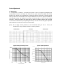
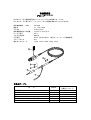
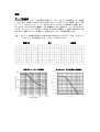
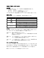
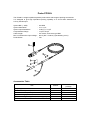
Probe PP006L
The PP006L is a high impedance passive probe with a wide range of probing accessories.
It is designed to give high impedance probing capability to a circuit when attached to a
LeCroy Oscilloscope.
System BW (-3dB)
System Attenuation
System Input Resistance
Compensation Range
Cable Length
Max. non-destructive input voltage
Probe Sense
:
:
:
:
:
:
:
350 MHz
10×±2 %
10 M (Ω) // 14 pF
14 pF to 23 pF
2.0 meters, Connector type BNC
600 V (DC + Peak AC) (see derating curve)
Yes
6
5
4
3
1
2
Accessories Table
①
②
③
④
⑤
⑥
Item
PP006L
PK116 accessory
package
Sprung hook
Ground lead (11 cm)
Ground lead on probe tip
IC Insulating tip
Color marking band (yellow, red, blue, green)
Trimmer tool
1
1
1
1
4×2
1
1
1
1
1
4×2
1
Probe Adjustment
LF Adjustment
LF compensation is made by connecting the probe to the CAL signal and adjusting the
compensation trimmer in the BNC-box at end of the probe. Connect the BNC end of the
PP006L to a channel of the oscilloscope. Connect the sprung hook end (1) and the ground
lead (2) to the CAL out and GND on the scope Calibrator area. The CAL signal is available in
many speeds. Select the Utilities in the scope to set the CAL to 1 kHz. Turn the scope
channel on. Press Auto Setup and adjust the time base and volts/div settings until the signal
on the screen contains two cycles (see figures below). Use the Trimmer tool (6) to adjust the
probe response to match the correct trim shown below.
[Note] Do not apply excess pressure to the screwdriver when you use it.
screwdriver is easy to brake, because of made by plastics.
Undershoot
Correct
Typical Voltage Derating Curve
The tip of
Overshoot
Typical Input Impedance
1.0E+08
1.0E+07
Zin[ohms]
1.0E+06
1.0E+05
1.0E+04
1.0E+03
1.0E+02
1.0E+00
1.0E+02
1.0E+04
1.0E+06
Frequency[Hz]
1.0E+08
1.0E+10
Installation for Safe and Efficient Operation
Operating Environment
Before using the Probe, ensure that its operating environment will be maintained within these
parameters :
Operation
: In-door Use
Temperature : 5 to 40 oC or 41 to 104 oF
Humidity
: < 80 % RH (non-condensing)
The Probe has been designed to comply with EN61010-1 Installation (Overvoltage) Category
II, 600 V, Pollution Degree 2.
Safety Symbols
Wherever the following safety symbols appear on the Probe or in the instruction manual, they
alert the user to an aspect of safety.
Symbol
CAUTION
WARNING
Meaning
Refer to accompanying documents (for Safety-related
information).
Risk of electric shock.
Calls attention to a procedure, practice or condition that
could possibly cause damage to equipment.
Calls attention to a procedure, practice or condition that
could possibly cause bodily injury or death.
Usage
The probe is intended to be used only with instruments which are connected to earth ground
through the input BNC connector. Connect the grounding terminal of the probe to the ground
potential of a device to be measured.
WARNING
Do not disconnect the probe while it is connected to a voltage source.
Do not directly touch a measuring point. Do not use the probe in wet or
explosive atmospheres.
WARNING
Probe tips are sharp, misuse can result in injury. Use with care.
The use of the probe and/or the instrument it is connected to in a
manner other than specified may impair the safety mechanisms.
CAUTION
To guarantee accurate performance characteristics, mechanical shocks
should be avoided, as well as damage to the cable through excessive
bending. Do not exceed the maximum specified signal voltage levels
(See Specifications).
Cleaning and Maintenance
The exterior of the probe and cable should only be cleaned using a soft cloth moistened with
water or isopropyl alcohol. The use of abrasive agents, strong detergents, or other solvents
may damage the probe. Assure that the input receptacles are free of debris before inserting
connection accessories.
All repair and maintenance should be referred to qualified service personnel. Do not use the
probe if any part is damaged.
Sales & Service
LeCroy Corporation Headquarters
700 Chestnut Ridge Road
Chestnut Ridge, NY 10977-6499
Tel (914) 425 2000
Fax (914) 425 8967
LeCroy S.A. (European Headquarters)
2, Rue du Pre-de-la-Fontaine
1217 Meyrin 1, Geneva,
Switzerland
Tel: 41 22 719 2111
Fax: 41 22 782 3915
Copyright, January 1999. LeCroy is a registered trademark of LeCroy Corporation.
All rights reserved. Information in this publication supercedes all earlier versions.
Specifications subject to change without notice.
取扱説明書
プローブ PP006L
PP006L は、広い測定範囲を持つハイインピーダンスの受動プロ-ブです。
オシロスコープに取り付け、ハイインピーダンス回路を測定することができます。
周波数帯域幅(-3dB)
減衰比
入力 RC
波形補償可能な入力容量
ケーブル長さ
コネクタの形式
入力耐圧
プロ-ブセンス
適合オシロスコープ
:
:
:
:
:
:
:
:
:
350 MHz
10 : 1±2 %以内
10 MΩ//14 pF
14 pF から 23 pF まで
2.0 m
BNC 形
600 V(DC+Peak AC)(耐圧ディレーティング曲線参照)
あり
LT322, LT34x, LT364, LT35x, LT37x
6
5
4
3
1
2
付属品テーブル
項
目
① 矢型チップ
② グランドリ-ド(11 cm)
③ アースアタッチメント
④ IC テストチップ
⑤ マークバンド(黄、赤、青、緑色)
⑥ドライバ-
PP006L
PK107
付属品パッケージ
1
1
1
1
4×2
1
1
1
1
1
4×2
1
調整
プローブ位相調整
低域周波数補償は、プロ-ブを信号源に接続して、プロ-ブボックスの補償トリマーを調整
して行います。PP006L の BNC コネクタをオシロスコープのチャンネルに接続します。矢型
チップ(1)とグラウンドリ-ド(2)をオシロスコープの CAL と GND 端子に接続します。
オシロスコープの UTILITIES 機能で、CAL 周波数を 1kHz に選びます。チャンネルを ON に
します。オートセットアップを押し、volts/div と time/div を調整して、波形を下図のように設
定します。付属のドライバ-を使用して下図のようにプロ-ブ位相を調整します。
注意 : ドライバーは樹脂で出来ていますので強い力を加えないで下さい。プローブのトリマ
ーにドライバーの先端を合わせて、ドライバーを回して下さい。
補償不足
適正
過補償
耐圧ディレーティング曲線
入力インピーダンス特性(特性例)
1.0E+08
1.0E+07
Zin[ohms]
1.0E+06
1.0E+05
1.0E+04
1.0E+03
1.0E+02
1.0E+00
1.0E+02
1.0E+04
1.0E+06
Frequency[Hz]
1.0E+08
1.0E+10
安全にご使用いただくために
動作環境
規定の環境でご使用ください。プロ-ブを使用できる温湿度範囲は次の通りです。
動作環境 : 屋内使用
温
度 : 0 ℃~40 ℃(性能保証温度は 10 ℃~35 ℃)
湿
度 : 40 ℃にて <90 %RH(結露しないこと)
プロ-ブは、EN61010-1、設置(過電圧)カテゴリーII、600 V、汚染度 2 に適合しています。
安全シンボル
安全を促すために、プロ-ブと取扱説明書に、警告記号が記載されています。
シンボル
意
味
添付書類を参照してください(安全に関する注意事項)。
感電の危険。
注 意
警 告
用
ここに記載されている事項を無視して、誤った取り扱いをす
ると、人が傷害を負うまたは機器が破損する可能性が想定さ
れます。
ここに記載されている事項を無視して、誤った取り扱いをす
ると、人が死亡するまたは重傷を負う可能性が想定されます。
法
プロ-ブは、入力 BNC コネクタを通じてグランドと接続される機器だけに使用して下さい。
プローブのアースリードを、測定される機器のグランドに接続して下さい。
警 告
規定以上の電圧を加えないでください。
測定ポイントに直接手を触れないでください。周囲に爆発性のガスがある場
所で使用しないで下さい。
警 告
プローブの先端は鋭くなっています。取り扱いには注意してご使用ください。
プローブと被測定物は確実で安全に接続して下さい。
注
ケーブルを無理に曲げたり、衝撃を与えないでください。性能を保証できま
せん。入力端子に規定以上の電圧を加えないでください。
意
クリーニングとメンテナンス
プローブとケーブルの掃除は、水または中性洗剤(薄めたもの)によって湿った柔らかい布
きれをご使用下さい。強い洗剤、または他の溶媒の使用は、変色したり、予期しない障害の
原因になります。付属品が装着されるプローブの先端が破損していないかご確認下さい。
修理とメンテナンスは、サービスの資格を持った人が行って下さい。
販売およびサービス
連絡先は、下記のセールスネットワーク、サービスネットワークをご利用ください。
セ−ルスネットワ−ク:
営
■ 国
■ 海
業
内
外
営
営
部
業 〒168-8511 東 京 都 杉 並 区 久 我 山
業 〒168-8511 東 京 都 杉 並 区 久 我 山
1 - 7 - 4 1 TEL(03)5370-5474 FAX(03)5370-5492
1 - 7 - 4 1 TEL(03)5370-5483 FAX(03)5370-5492
■ 東 日 本 営 業 所 〒980-0803 仙台市青葉区国分町 2-14-18(定禅寺パークビル 8F) TEL(022)224-0501 FAX(022)261-6201
■ 中 部 営 業 所 〒460-0003 名 古 屋 市 中 区 錦 1 - 3 - 2 ( 中 央 伏 見 ビ ル ) TEL(052)211-2731 FAX(052)211-5418
■ 西 日 本 営 業 所 〒541-0054 大 阪 市 中 央 区 南 本 町 3 - 6 - 1 4 ( イ ト ウ ビ ル ) TEL(06)6243-4533 FAX(06)6243-4675
サ−ビスネットワ−ク:
■ サ ー ビ ス 部 〒168-8501 東 京 都 杉 並 区 久 我 山 1 - 7 - 4 1 TEL(03)5370-5172 FAX(03)5370-5258
■ 西 日 本 営 業 所 〒541-0054 大 阪 市 中 央 区 南 本 町 3 - 6 - 1 4 ( イ ト ウ ビ ル ) TEL(06)6243-4533 FAX(06)6243-4675
■ 会 津 サ ー ビ ス 課 〒965-0855 福 島 県 会 津 若 松 市 住 吉 町 3 1 0 TEL(0242)26-4339 FAX(0242)26-4348
お問合わせ窓口
ハロ-イワツウ
技術的な、取扱い・測定方法など
計測担当
フリーダイヤル
0120-086-102
(受付時間:土曜、日曜日を除く、営業日の 9:00~12:00、13:00~17:30)
修理納期など
会津サービス課
フリーダイヤル
0120-267-905
(受付時間:土曜、日曜日を除く、営業日の 9:00~12:00、13:00~17:00)
● URL : http://www.iti.iwatsu.co.jp
● E-mail : [email protected]
お願い: セールスネットワーク、サービスネットワークの最新情報は、当社のホームページまたは
フリーダイヤルでご確認いただくようお願い申し上げます。
KML044821
B1101-714500(B)