1
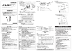
形 D6FZ-FGT□□□ エア流量センサ 取扱説明書 このたびは、本製品をお買い上げいただきまして、 まことにありがとうございます。 ご使用に際しては、次の内容をお守りください。 ・電気及び空気圧の知識を有する専門家が扱ってください。 ・この取扱説明書をよくお読みになり、十分にご理解のうえ、 正しくご使用ください。 ・この取扱説明書はいつでも参照できるように大切に保管してください。 © OMRON Corporation 2013 All Rights Reserved. 1607115-8A 安全上のご注意 ● 警告表示の意味 警告 正しい取扱いをしなければ、 この危険のために、 軽傷・中程度の 傷害を負ったり、 万一の場合には重傷や死亡に至る恐れがあり ます。 また、 同様に重大な物的損害をもたらす恐れがあります。 注意 正しい取扱いをしなければ、 この危険のために、 時に軽傷・中 程度の傷害を負ったり、 あるいは物的損害を受ける恐れがあり ます。 ● 警告表示 警告 可燃性ガスを使用すると爆発する恐れがあります。 可燃性ガスでは、使用しないでください。 注意 破裂により万が一の場合、怪我をする恐れがあります。 仕様範囲流量および圧力以上で使用しないでください。 また、空気・窒素以外の気体で使用しないでください。 本体内に、水滴・オイルミスト・埃が流入すると、計測誤差や破 壊につながる可能性があります。流体は清浄気体を使用してくだ さい。配管上流部にフィルタ、ミストセパレータを設置してくだ さい。また、配管内に残っている埃はエアブローなどで除去して から設置してください。 10. 本製品を落下させるなどの強い衝撃を与えないでください。強い衝撃を与えてし まった場合、 使用を中止してください。 11.RS-485通信線に電源を接続しないでください。製品破損の恐れがあります。 12.流路内の整流板には手を触れないでください。手を切る可能性があります。 13.配管時のスパナ等での本体の固定は必ず本体コンジット部で実施してください。他 の部分で固定すると製品破損の恐れがあります。 14.片側バラ線ケーブル (形D6FZ-JD□A、 別売) の青色線(0V)は必ずシールド線と接 続してください。 (青色線とシールド線は形D6FZ-JD□A内部で接続されています。) ⑦操作キー 各キーの機能は下表の通りです。 操作・表示部 ① 本製品の動作不能、誤動作、または性能・機能への悪影響を防ぐため、以下のこと を守ってください。 1. 設置場所について 下記の設置場所では使用しないでください。 ・周囲温度が定格の範囲を超える場所 ・周囲湿度が定格の範囲を超える場所 ・海抜 2,000mを越える場所 ・腐食性ガス、可燃性ガスがある場所 ・塩分、鉄粉がある場所 ・振動や衝撃が直接加わる場所 ・屋外および直射日光があたる場所 ・水・油・化学薬品の飛沫がある場所 ・強磁界、強電界、強帯電物がある場所 2. 電源および配線について ・電源ラインにサージが確認された場合、環境に応じてサージアブソーバを接続ください。 ・電源ライン / 出力ライン接続時には、極性に注意して接続してください。また、定格を 超える電圧を印加しないでください。 ・電源ライン接続時は、電源を短絡しないでください。 ・出力ライン接続時は、定格を超える電流を流さないでください。 ・高圧線、動力線と本製品の配線は別配線としてください。同一配線あるいは同一ダク トにすると誘導を受け、誤動作あるいは故障の原因となります。 ・電源が印加された状態でコネクタの挿抜をおこなわないでください。 3. 設置について ・アナログ出力、制御出力を使用する際にはケーブル長 30m 未満で使用ください。 ・エア流量ステーション(形 D6FZ-FGX21、別売)と組み合わせて使用する場合は、 電源電圧を DC24V としてください。 ・RS-485 通信にて30m∼100mで使用する場合は、必ず青色線 (0V) とシールド線を 接地してください。 ■ 用途について 本製品エア流量センサは、製造現場で使用される圧縮エアの流量を測定できます。 そのデータを解析することで、圧縮エアの漏れなどが発見でき、省エネに貢献します。 本製品は以下の特長があります。 ・曲管部直後に取り付け可能です。 ・低流量の測定精度がよく、 圧縮エアの漏れ発見が容易です。 ・エア流量ステーション (形 D6FZ-FGX21、 別売) に接続することで流量のロギングが 行えます。 ■ 定格/性能 項目 適応流体 使用圧力 耐圧 計測範囲 *2) 精度保証範囲*2) 表示分解能 *2) 精度 *2) 温度特性 繰り返し精度 周囲温度範囲 周囲湿度範囲 電源電圧 消費電流 機能 表示灯 入出力 保護構造 配管接続径 材質 質量(梱包状態) 付属品 形D6FZ-FGT200 形D6FZ-FGT500 空気・窒素(N2)*1) 0.75MPa以下 1.5MPa 0∼200L/min 0∼500L/min 2∼200L/min 5∼500L/min 1 L/min 50L/min以上のとき ±2% F.S. 50L/min未満のとき ±0.5% F.S. ±3% F.S. ±1% F.S. 使用時:-10∼60℃ 保存時:-20∼70℃(結露・氷結無きこと) 使用時:25∼90%RH 保存時:0∼90%RH (結露・氷結無きこと) DC12∼24V±10% 120mA以下 瞬時流量値表示/積算流量値表示/反転表示/ ゼロ点調整/ピーク・ボトムホールド/キーロック/ エコモード/スケーリング(アナログ出力)/ 判定ヒステリシス/ティーチング 11セグデジタル表示(赤色)/RUN/FUN/THR表示(黄色) OUT1/OUT2表示(黄色)/キーロック表示(黄色) 流量単位表示(緑色)/反転時流量単位表示(黄色) 制御出力2系統、アナログ出力1系統、RS-485通信1系統 IP65 Rc1/4 (8A) Rc1/2 (15A) 本体:PBT、流路:亜鉛 約400g(約500g) 取扱説明書 *1) ダスト、オイルミストを含まない乾燥・清浄気体であること。 *2) 流量の表記は、0℃、大気圧(101.3kPa)の流量に換算した値です。 名 称 機 能 RUN/FUN/THR モードの切り替え MODE キー キーロックの設定・解除 (RUN モード時、長押し *) 設定値のキャンセル(FUNモード・THRモード設定中) 設定項目の移動 使用上の注意 安全上の要点 本製品を安全に使用するため、以下のことを守ってください。 1. 定格電圧を越える電源は使用しないでください。 2. 電源は、高電圧が発生しないように対策 (安全超低電圧回路) されている直流 電源装置から供給してください。 3. 電源の逆接続はしないでください。 4. 出力は短絡しないでください。 5. 指定以外の気体、液体で使用しないでください。 6. 製品は、規定のトルクで固定してください。 7. 製品に強い圧縮力、 引張力が掛かる場所には設置しないでください。 8. 本製品を分解・修理・改造しないでください。 9. 廃棄するときは、産業廃棄物として処理してください。 ■ 各部の名称と機能 項目選択キー / 表示内容の切り替え 設定値の変更 (FUNモード・THRモード設定中、 長押し * で高速表示切り替え) 表示部の上下反転(RUN モード時、長押し *) 設定値などの確定 SETキー 整流板 ② ② *) 長押し:同一キーを 3 秒以上押し続けてください ■ 配管について 適用口径 形 D6FZ-FGT200:8A、形 D6FZ-FGT500:15A 適用配管時の注意 ・配管時は本体コンジット部をスパナ等で固定し、下表の締め付け トルクの範囲でしっかり締め付けてください。 ⑤ ③ ゼロ点調整の設置・解除 (RUNモード時、長押し*) オートティーチングの設定 (THRモード時、長押し*) *形D6FZ-FGT500の図となります。 操作・表示部 (拡大) □ ④ 形式 形 D6FZ-FGT200 形 D6FZ-FGT500 ⑦ ⑥ ①外部接続コネクタ エア流量センサを別売りの専用接続ケーブル(形 D6FZ-JD□□)に接 続するコネクタです。 締め付けトルク 12 ~ 14N・m 31 ~ 33N・m ・配管時は本体コンジット部のみ固定してください。他の部分で固 定すると製品破損の恐れがあります。 ・本体コンジット部をスパナ等で固定する際には、ウエス等で本体 を保護して固定してください。直接固定した場合は本体コンジッ ト部にキズが付く場合があります。 ・流れ方向を確認してから取り付けてください。 ・配管時に本体に異物が入らないようにしてください。 ・本体コンジット部以外や外部接続コネクタに力を加えないでく ださい。 ②コンジット 配管を取り付けるためのメネジです。配管径は形 D6FZ-FGT200: 8A、形 D6FZ-FGT500: 15A です。 流れ方向 ③動作モード/出力表示灯 動作モードおよび、出力状態を表示します。各動作モードでの表示状 態は下表の通りです。 動作モード 表示灯 RUN 点灯・消灯 *2) THR/OUT1 *1) FUN/OUT2 *1) RUN FUN 消灯 点滅 消灯 点灯・消灯 *2) 点灯 THR 点滅 消灯 消灯 *1) RUN モード時、THR は OUT1、FUN は OUT2 の表示灯となります。 *2) 設定したしきい値および出力機能に応じて点灯・消灯します。 しきい値は THR モードで、出力機能割り当ては FUN モードで設定してください。 ■ 取付姿勢について 配管は水平に取り付けてください。水平以外の取付姿勢では計測精 度が低下します。また、表示・操作部を下向きにして取り付けると 配管内のミスト、ダストが堆積し故障の原因となります。 ④11 セグ表示灯 流量や設定などの各種表示を行います。 1 2 3 4 5 6 7 8 9 > 0 < _ ○ 操作・表示部が上向き A O B P C Q D R E S F T G U H V I W J K L Z M ■ 取付について N X Y L/h 計測単位 m3/min × 操作・表示部が下向き 専用取付金具(形 D6FZ-FC03、別売 ) をご使用いただけます。 (1) 本体と専用取付金具の取付け (2) 専用取付金具の取付け Σ(積算) M3ネジ ⑤単位表示 流量の計測単位を表示します。 モード 瞬時流量 積算流量 L/min L ⑥キーロック表示 キーロック時に点灯します。 m3/h m 3 M3ネジ M3 ネジ締め付けトルク 0.59 ∼ 0.61N・m ■ 各モードでの動作 ●モード切替 ・切替方法 MODEキーで RUNモード → FUNモード → THRモード を切り替えます。 RUNモード THRモード FUNモード [ 0 ] [ ΣCLR 瞬時流量 ] 積算値初期化 RUNモードの操作 HI [ 100 ] 上限しきい値 FUNモードの操作 THRモードの操作 *)THR モードから RUN モードへの切り替え時、計測が完了するまでの間「-----」が表示されます。 ●基本操作 ・各モード表示切替 / 項目選択 項目選択キーで 各モードの項目表示を切り替えることができます。 キーで順方向に、 キーで逆順方向に切り替わります。 ・設定方法 (FUNモードおよびTHRモード時) (例)THRモード 下限しきい値の変更 LOW 項目選択キーで設定を変更したい項目を表示、 SETキーで決定 100 下限しきい値 [ ] □ LOW 値の点滅中に項目選択キーで設定値を 選択 100 下限しきい値 [ ] LOW 点滅 50 [ □ ] LOW 50 設定が確定され、点滅が点灯に戻る 下限しきい値 ・流量の各測定値を表示します。各画面の表示内容を以下に示します。 RUNモード選択 100 *1) *2) [ ] ①瞬時流量 [ ] [ ] 5555 [ ] ②積算流量 [ ] PEK 200 [ ] [ ] [ ] BTM ④ボトム値 瞬時流量 *1) ゼロ点調整機能使用時の 瞬時流量表示 Z 100 ①瞬時流量 *2) ユニットNo.表示ON時 瞬時流量表示 U.1 100 ①瞬時流量 [ ] 100 [ ] [ ] LOW 積算流量 単位 L/min L/h m3/min m3/h L m3 形D6FZ-FGT200 形D6FZ-FGT500 0∼500 0∼200 0∼30.0K *) 0∼12.0K 0∼0.500 0∼0.200 0∼30.0 0∼12.0 0∼99999999 0∼99999.999 *) 単位[L/h]ではkL (キロリッター) 表示となるため” K” が付きます。 HI ② 下限しきい値 LOW ③ ローカッ ト しきい値 CUT ④ しきい値 ヒステリシス HYS 100 ②下限しきい値 [ ] *3) *3) *3) CUT 0 ③ローカットしきい値 設定値 100 0~200 250 0~500 100 0~200 250 0~500 0 0~200 0 0~500 5 HYS 2 ΣUP 瞬時流量判定にて、漏れとして無視する流量 設定値です。 1分間このしきい値を超えたとき に出力判定を確定します。 積算流量判定 ΣUP しきい値 (上4桁) 9000 0000∼9000 積算流量のカウントアップ判定出力用の しきい値 (上4桁) です (千万の位∼一万の位) 。 上下の設定で90000000Lが上限となります。 ⑥ 積算流量判定 ΣLO しきい値 (下4桁) 0000 0000∼9999 積算流量のカウントアップ判定出力用の (千の位∼一の位) 。 しきい値 (下4桁) です 値を設定しようとした場合、 自動的に上記条件に当てはまるしきい値に調整されます。 9000 ・判定出力について 各しきい値と、判定出力の対応を下表に示します。 (出力の割り当てについてはFUNモードにて設定可能です。) [ ] [ ] ΣLO 瞬時流量判定で必要な下限しきい値です。 1分間このしきい値を下回ったときに出力判定 を確定します。 *1) 表内上段はFGT200、 下段はFGT500の値を表しています。 *2) 単位設定が"L/min"の場合の数値です。 その他の単位を選択している場合には、 その単位系に合わせた数値が表示されます。 *3) 各しきい値を設定する際、 0≦ローカットしきい値≦下限しきい値≦上限しきい値≦計測範囲の上限値の順序をこえて各しきい ⑤積算流量判定 しきい値(上4桁) [ ] 瞬時流量判定で必要な上限しきい値です。 1分間このしきい値を超えたときに出力判定を 確定します。 ⑤ [ ] ④しきい値ヒステリシス 意 味 *1)*2) 2,4,6,8,10,12, HI, LOW, CUT のそれぞれのしきい値について、 14,16,18,20 チャタリングを防止するためのヒステリシスを設定 5,10,15,20,25, できます。 30,35,40,45,50 2 [ ] *) 押下時の流量がゼロの場合はゼロ点調整機能は動作しません。 流量表示 50 HI ・RUNモードその他の機能 ①ゼロ点調整機能 RUNモード/瞬時流量表示中にSETキーを3秒以上長押しすると、押下時 の流量* をゼロとして増減を表示します。昼・夜、季節ごとの流量の変化を把 握できます。 電源をOFFにし、再起動した後も、前回設定したゼロ点調整機能は有効の まま使用できます。 再度SETキーを3秒以上長押しするとゼロ点調整機能を解除できます。 ・設定単位と表示値の関係について 設定単位と数値表示範囲を下表に示します。 (単位はFUNモードで設定で きます。) ③ピーク値 上限しきい値 ①上限しきい値 [ ] 注)流量ステーションをFUNもしくはTHRモードに設定する際、接続してい る本製品がRUNモードであることを確認してください。 本製品がFUNもしくはTHRモードに設定されているときは、表示部に ”REMOTE” が表示されず、 流量ステーションの画面にエラーが表示され ます。 ① 初期値 *1)*2) THRモード選択 ④ボトム値表示 瞬時流量のボトム値を表示します。THRモード、FUNモードへのモード切替や 電源OFFを実施した場合、 ボトム値がリセットされます。 ④通信ロック機能 別売りの流量ステーション (形D6FZ-FGX21) と接続した場合、流量ステー ションがFUNもしくはTHRモードに設定されているときは、本製品の THR/FUN表示灯が点滅し、表示部に”REMOTE” が表示されます。 “REMOTE” が表示されているときは、製品本体でのキー入力を受け付け ません。流量ステーションの設定をRUNモードに戻すとREMOTE表示が解 除されます。 表示 項目 ・ しきい値の設定や表示を行います。 ③ピーク値表示 瞬時流量のピーク値を表示します。THRモード、FUNモードへのモード切替 や電源OFFを実施した場合、 ピーク値がリセットされます。 ③キーロック機能 RUNモード中にMODEキーを長押しすると、キーロック状態となります。 キー ロック中はFUNモード、THRモードは使用できません。 (RUNモードでの表示 の変更は可能です。) 解除する際は、再度MODEキーを長押ししてください。 ●RUNモード ●THRモード ②積算流量表示 積算流量を表示します。99999999Lまで表示可能です。 99999999Lを超えた場合、 0に戻ります。 積算値は10分ごとに内部メモリ (EEPROM) に記録されます。 ②表示反転機能 RUNモード中に項目選択キーを長押しすると、表示が反転します。取り付け 方向により、表示部が反転した際にご使用ください。 表示反転にあわせて項目選択キーの機能も反転します。 設定値を変更後、SETキーで決定 下限しきい値 ①瞬時流量表示 瞬時流量を表示します。 *1) ゼロ点調整機能使用時には、先頭に”Z” が表示されます。 *2) ユニットNo.表示ON時には、先頭に設定したユニットNo.(U.1∼U.8) が表示されます。 0000 ⑥積算流量判定 しきい値(下4桁) 注) 設定・変更方法は 「●基本操作」参照 TH1 瞬時流量がHIで設定したしきい値以上で出力します。 TH2 瞬時流量がLOWで設定したしきい値以下で出力します。 TH3 瞬時流量がHIで設定したしきい値以上、 またはLOWで設定したしきい値以下で出力します。 TH4 瞬時流量がHIで設定したしきい値以上のとき、 またはCUTで設定したしきい値以上かつLOWで設定したしきい値以下で出力します。 CNT 積算流量値が積算流量判定しきい値にて設定した値を超えた時に出力します。 ・TH1∼TH4の判定範囲について 以下の図はN.O (ノーマリーオープン) での判定です。 (N.C (ノーマリークローズ) では出力が反転します。) 【TH1の判定範囲】 【TH2の判定範囲】 【TH3の判定範囲】 出力 HI HI 瞬 時 流 LOW 量 CUT 瞬 時 流 LOW 量 CUT HI 出力 瞬 時 流 LOW 量 CUT 出力 出力 【TH4の判定範囲】 HI 瞬 時 流 LOW 量 CUT ・オートティーチングについて 上限しきい値、下限しきい値はオートティーチングが可能です。 オートティーチングを実施すると、上限しきい値ではモード切替直前のピーク値に20L/minを加えた値(形D6FZ-FGT500では50L/min)、 下限しきい値ではボトム値から20L/minを引いた値(形D6FZ-FGT500では50L/min)を反映させた値が設定されます。 オートティーチング実施設定値 形D6FZ-FGT200 形D6FZ-FGT500 上限しきい値 ピーク値 +20 ピーク値 +50 下限しきい値 ボトム値 -20 ボトム値 -50 ( unit : L/min ) <設定方法> ①THRモードにします。 ②項目選択キーで”HI” を表示させます。 (下限しきい値を設定する場合は”LOW” を表示させます。) ③SETボタンを長押しします。数秒後に値が更新されます。 (値が更新された時点でしきい値が確定します。) ④RUNモードにし、測定を開始します。 出力 出力 ●FUNモード ・各機能の設定・表示を行います。 機 能 表 示 初期値 設定値 (表示値) ∑CLR - ---- → OK ② 平均化回数設定 AVE 8 1, 2, 4, 8, 16, 32 ③ 表示反転設定 DIR ④ 単位表示設定 UNT ① 積算値初期化 FUNモード選択 [ ] ΣCLR [ ] ①積算値初期化 [ ] AVE 8 非反転表示時 意 味 積算流量値を0にクリアします。 表示が” OK” となるまでSETキーを長押ししてください。 平均化回数を設定します。 (設定値1は平均化なしとなります。) 反転表示時 瞬時流量の単位を設定します。設定が確定すると、RUNモード、FUNモードの一部、THRモード での各種しきい値設定も同じ単位に変更されます。 L/min, L/h, m3/min, m3/h L/min ②平均化回数設定 [ ] ⑤ [ ] 出力機能割り当て 設定 (OUT1) [ ] --- ---, PLS, TH1∼TH4, CNT, ERR N.O/N.C N.O N.O, N.C ⑧ パルス出力間隔設定 PLS 10 ⑨ スケーリング設定 SCL OFF OFF, DISP 4mA対応流量値 4_ _ 0 0∼200(FGT200) 0∼500(FGT500) 20mA対応流量値 20_ ⑥ [ ] UNT [ ] A ⑨スケーリング設定” DI SP” 選択時の表示 ④単位表示設定 (FGT200の場合) [ ] SCL OUT1 - - - DISP [ ] [ ] [ ] 4_ _ --- 0 4mA対応流量値 ⑥出力機能割り当て設定(OUT2) [ ] [ ] 20_ N.O/N.C N.O 200 [ ] [ ] [ ] ⑩シリアル通信設定 10 ⑧パルス出力間隔設定 [ ] [ ] SCL OFF ⑨スケーリング設定表示 A [ ] B ⑩シリアル通信設定 ” DI SP” 選択時の表示 SER SER OFF B [ ] ECO OFF ⑪エコモード [ ] U.No [ ] [ ] DISP ⑩シリアル通信設定 [ ] ⑩シリアル通信設定 01 ユニットNo.設定 [ ] [ ] INIT ⑫パラメータ初期化 [ ] U.No OFF [ ] 10, 100, 1000 *2) BAU 115.2 ボーレート [ ] [ ] 8bit データ長 [ ] オープンコレクタ出力のOUT1、OUT2の出力状態の設定です。 ノーマリ―オープン (N.O) 、 ノーマリ―クローズ (N.C) です。 *1) EVEN パリティ [ ] [ ] STP 1BIT ストップビット [ ] TER ON 通信ターミネータ設定 [ ] 0∼200(FGT200) 0∼500(FGT500) *3) ⑩ シリアル通信設定 SER OFF OFF, DISP ユニットNo.設定 U.No 01 01∼08 パルスを出力する間隔を設定します。 (設定値"100"は100L毎のパルス出力を意味し、 100L毎に50ms幅固定のパルス出力を行います。) アナログ出力のスケーリングを実施する場合は"DISP"を選択してください。"DISP"を選択すると、 設定メニューが現れます (左図*1)参照) 。"OFF"を選択すると、設定メニューは隠れます。 *2) *2) 4mAに対応する瞬時流量値を入力します。※) 20mA対応流量値以上には設定できません。 20mAに対応する瞬時流量値を入力します。※) 4mA対応流量値以下には設定できません。 RS-485シリアル通信の設定を実施する場合は"DISP"を選択してください。"DISP"を選択すると、 設定メニューが現れます (左図*2)参照) 。"OFF"を選択すると、設定メニューは隠れます。 ※別売りの流量ステーション (形D6FZ-FGX21)に接続する場合は、 ユニットNo.と通信ターミ ネータ設定以外の設定は変更しないでください。 ユニットNo.を設定します。 ユニットNo.表示設定 U.No OFF OFF, DISP ボーレート BAU 115.2 9.6, 19.2, 38.4, 115.2 データ長 DAT 8BIT 7BIT, 8BIT データ長を設定します。 パリティ PRY EVEN EVEN, ODD, NONE パリティを設定します。 ストップビット STP 1BIT 1BIT, 2BIT 通信ターミネータ設定 TER ON ON, OFF ⑪ エコモード ECO OFF ON, OFF ⑫ パラメータ初期化 INIT - ---- → OK RUNモードの瞬時流量表示画面での、 ユニットNo.表示のON/OFFを設定します。 ボーレートを設定します。 (単位は[kbps]です。) ストップビットを設定します。 センサ内部の終端抵抗(120Ω) のON/OFFを選択します。内部終端抵抗を使用する際には "ON"を選択してください。 数値・単位表示を消灯するモードです。エコモードをONした場合は以下の動作となります。 ・RUNモードで10秒以上操作が無い場合、RUN, OUT1/2表示灯のみ表示します。 ・各種設定ボタン押下で通常表示になります。 ・THR, FUNモードには適用されません。 パラメータの初期化を実施します。 表示が” OK"となるまでSETキーを長押ししてください。 *1)単位設定が"L"の場合の数値です。 その他の単位を選択している場合には、 その単位系に合わせた数値が表示されます。 *2)単位設定が"L/min"の場合の数値です。 その他の単位を選択している場合には、 その単位系に合わせた数値が表示されます。 *3)通信の仕様については別途お問い合わせください。 [ ] PRY [ ] 200(FGT200) 500(FGT500) [ ] DAT 注) 設定・変更方法は 「●基本操作」参照 *1) [ ] ユニットNo.表示設定 [ ] ⑦ 出力反転設定 20mA対応流量値 ⑦出力反転設定 PLS OUT2 [ ] [ ] [ ] 出力機能割り当て 設定 (OUT2) ⑨スケーリング設定表示 ⑤出力機能割り当て設定(OUT1) [ ] OUT2 出力端子OUT1、 2に割り当てる出力機能を選択します。 ・---:出力なし ・PLS:パルス出力 (出力単位の設定は、FUNモード内の「パルス出力間隔設定」 で実施してください。) ・TH1∼4, CNT:判定出力 (詳細は 「●THRモード・判定出力」 を参照ください。) ・ERR:エラーが発生した際に出力します。 OUT1 DIR ③表示反転設定 表示の反転・非反転を設定します。 [ ] ⑪エコモード ■エラーモードについて 表 示 エラーの意味 ERR-01 ERR-02 内部メモリ異常 ・高圧線、動力線などの影響を受けた可能性があります。 配線の見直しを行ってください。 センサ異常 ・エアの流れ方向と逆向きに取り付けられていないか確認してください。 ・定格以上のエアが流れていないか確認してください。 ・高圧線、動力線などの影響を受けた可能性があります。 配線の見直しを行ってください。 ERR-03 ERR-04 対 処 方 法 ■ 外形図 ■ 配線について ・形D6FZ-FGT□□□ ・エア流量ステーション (形D6FZ-FGX21 別売) と接続する場合 エア流量ステーションには形D6FZ-FGT□□□と別売りの形D6FZ-FGS1000を組み合わせて使用できます (最大8台) 。 接続ケーブル (長さ1.5m) 70 形 D6FZ-FGS1000 と組み合わせて使用する場 合は、 D6FZ-FGS1000 の取扱説明書に従ってく ださい。 形D6FZ-FGT□□□ (本製品) [単位:mm] 60 (*) Rc1/4 15 77 x10 30 (*) Rc1/4 (*) D6FZ-FGT500は Rc1/2となります。 (*) D6FZ-FGT500は Rc1/2となります。 [単位:mm] 4-M3 x 5 ・形D6FZ-FC02 (56) 13.6 2) 10 13.6 CN2 CN1 φ14.9 M12プラグ M12ソケット 孔 通 貫 .5 4 φ *)FUNモードにてOUT1/OUT2を任意の出力に設定できます。 φ14.9 出力内容 *) 18 DC26.4V 以下 50mA 以下 ( 残電圧2V 以下 ) パルス出力 ( パルス幅 約 50ms) 判定出力 本体異常出力 φ14.9 *ケーブル長は 30m未満と してください。 ①安全を確保する目的で直接的または間接的に人体を検出する用途に、本製品を使用 しないでください。同用途には、当社センサカタログに掲載している安全センサをご使用 ください。 ②下記用途に使用される場合、当社営業担当者までご相談のうえ仕様書などによりご確 認いただくとともに、定格・性能に対し余裕を持った使い方や、万一故障があっても危 険を最小にする安全回路などの安全対策を講じてください。 a)屋外の用途、潜在的な化学的汚染あるいは電気的妨害を被る用途 またはカタログ、取扱説明書等に記載のない条件や環境での使用 b)原子力制御設備、焼却設備、鉄道・航空・車両設備、 医用機械、 娯楽機械、 安全装置、 および行政機関や個別業界の規制に従う設備 c)人命や財産に危険が及びうるシステム・機械・装置 d)ガス、水道、電気の供給システムや24時間連続運転システムなどの 高い信頼性が必要な設備 e)その他、上記 a) ∼ d) に準ずる、高度な安全性が必要とされる用途 *上記は適合用途の条件の一部です。当社のベスト、総合カタログ・データシート等最新版 のカタログ、 マニュアルに記載の保証・免責事項の内容をよく読んでご使用ください。 0V 負荷電源電圧 負荷電流 [単位:mm] 〈裏面〉 ・形D6FZ-JD□A ・片側バラ線ケーブル(形 D6FZ-JD□A)配線色 インダストリアルオートメーションビジネスカンパニー 39.5 *青色線(0V)は必ずシールド線と接続してください。 ■ リニア出力について ■ T分岐コネクタ結線図 1 OUT1 1 1 1 OUT1 2 DC24V *1 2 2 2 DC24V *1 3 アナログ出力1 3 3 3 アナログ出力1 4 NC 4 4 4 NC 5 RS-485(+) 5 5 5 RS-485(+) 6 RS-485(-) 6 6 6 RS-485(-) 7 0V 7 7 7 0V 8 OUT2 8 8 8 OUT2 出力方式:電流(4-20mA)吐き出し方式 負荷抵抗:300Ω以下 出力内容:瞬時流量 2 ●製品に関するお問い合わせ先 お客様相談室 プラグCN2(IN) ソケットCN0(OUT) 1 L 3 4 5 6 7 形式 D6FZ-JD3A D6FZ-JD10A D6FZ-JD20A M12 ソケット [単位:mm] メイバン L 3000 10000 20000 3 NC 出荷時は以下の値に設定されています。 4 NC 形D6FZ-FGT200 形D6FZ-FGT500 0L/min 200L/min 0L/min 500L/min 5 RS-485(+) 6 RS-485(-) 7 0V 8 NC *1 エア流量ステーション (形 D6FZ-FGX21、 別売) と 接続する場合は、 電源を DC 24V としてください。 *2 ソケットCN1に接続した エア流量センサRS-485以外 の出力は、結線されません。 39.5 43 L 26.8 [単位:mm] オムロン 携帯電話・PHS・IP電話などではご利用いただけませんので、下記の電話番号へおかけください。 電話 ・形D6FZ-JD□B 8 クイック 055-982-5015(通話料がかかります) ■営業時間:8:00∼21:00 ■営業日:365日 M12 プラグ 26.8 ソケットCN1(OUT)*2 1 NC 2 DC24V *1 0120-919-066 +150 0 +300 0 +600 0 M12 ソケット メイバン 形式 D6FZ-JD3B D6FZ-JD5B D6FZ-JD10B D6FZ-JD20B L 3000 5000 10000 20000 +150 0 +200 0 +300 0 +600 0 φ15 被覆色 信号名 ピンNo. 1 白 パルス/判定/本体異常選択出力1 2 茶 DC12∼24V 3 黒 アナログ出力 4 黄 NC(未使用) 5 灰 RS-485(+) 6 桃 RS-485(-) 7 青+シールド 0V 8 赤 パルス/判定/本体異常選択出力2 26.8 φ15 シールド φ15 形D6FZ-FGT□□□ (本製品) OUT1 OUT2 内 部 回 路 出力段回路図 電源 (DC12∼24V) アナログ出力 4mA 20mA 15 CN0 形D6FZ-FGT□□□内部 片側バラ線ケーブル 形D6FZ-JD□A ご使用に際してのご承諾事項 深さ NPNオープンコレクタ出力 2) 深さ グリ φ8(ザ (ザ 出力方式 32.1 ■ 制御出力について φ4 12 M12ソケット 通孔 .5貫 17.7 グリ 最大8台まで接続可能 24.7 φ8 形D6FZ-FGS1000 ・エア流量センサを単独で使用する(アナログ出力、パルス出力を使用する) 場合 x10 7 49.5 ±0.1 16 ±0.1 ・・・ 1 49.5 47 エア流量ステーション (形 D6FZ-FGX21、 別売) と接続する場合は、 電源を DC24V と してください。 形 D6FZ-FGT□□□ーエア流量ステーション間 および形 D6FZ-FGT□□□ー電源間のケーブル 長を 30m∼ 100mで使用する場合は、 必ず青色 線 (0V) とシールド線を接地してください。 5.25 15 両側コネクタ ケーブル 形D6FZ-JD□B 2 3. .2 Ø .3 4- -Dia 4 33.7 電源ーエア流量センサ間および 電源ーエア流量ステーション間、 エア流量センサーエア流量ステーション間の 最大延長ケーブル長は 100m です。 25 12.65 63.7 CN0 形D6FZ-FGT□□□ (本製品) 5 16 推奨取り付け穴寸法 89.65 電源 (DC24V) 両側コネクタ ケーブル 形D6FZ-JD□B 5 1.7 8-R 40 片側バラ線ケーブル 形D6FZ-JD□A T分岐コネクタ 形D6FZ-FC02 両側コネクタ ケーブル 形D6FZ-JD□B 4-3 30 CN1 8.5 49.5 ±0.1 CN1 48 両側コネクタ ケーブル 形D6FZ-JD□B CN2 CN2 エア流量ステーション 形D6FZ-FGX21 エア流量ステーションの 使用方法につきましては、 エア流量ステーションに 付属の取扱説明書、スター トアップガイド、ユーザー ズマニュアル(PDF)をご 覧ください。 CN1 60 40 16 CN0 CN2 4 CN0 両側コネクタ ケーブル 形D6FZ-JD□B 4-3.5 T分岐コネクタ 形D6FZ-FC02 16 ±0.1 T分岐コネクタ 形D6FZ-FC02 ・形D6FZ-FC03 4- Ø 3.2 ±0.1 ●FAXやWebページでもお問い合わせいただけます。 FAX 055-982-5051 / www.fa.omron.co.jp ●その他のお問い合わせ 納期・価格・サンプル・仕様書は貴社のお取引先、または貴社 担当オムロン販売員にご相談ください。 オムロン制御機器販売店やオムロン販売拠点は、Webページで ご案内しています。 A r 2012年8月 model D6FZ-FGT Air Flow Sensor INSTRUCTION SHEET Thank you for selecting OMRON product. This sheet primarily describes precautions required in installing and operating the product. Before operating the product, read the sheet thoroughly to acquire sufficient knowledge of the product. For your convenience, keep the sheet at your disposal. © OMRON Corporation 2013 All Rights Reserved. PRECAUTIONS ON SAFETY ● Meanings of Signal Words WARNING CAUTION Indicates a potentially hazardous situation which, if not avoided, will result in minor or moderate injury, or may result in serious injury or death. Additionally there may be significant property damage. Indicates a potentially hazardous situation which, if not avoided, may result in minor or moderate injury or in property damage. ● Warning Indications WARNING The use of flammable gases may cause explosion. Do not use the product with flammable gases. CAUTION Injury may occur due to explosion. Flow rate and pressure must be within the range of ratings. Don’t measure other than air and nitrogen gas. If water drop, oil, mist and dust flow in the body, it may mismeasurement and destruction. Use clean fluid. Dust and mist can affect the characteristics of Sensor or damage the Sensor. Install a filter and mist separator on the upstream tube. Moreover, install an air flow sensor after removing the dust remaining in pipe by something like air blow. PRECAUTIONS FOR SAFE USE Observe the following precautions to ensure safe operation. 1. Do not use the power supply that exceeds rated voltage. 2. Use a DC power supply unit provided with anti-voltage design (safety extra low voltage circuit) to supply power to the product. 3. Do not connect the power supply in reverse. 4. Do not short-circuit outputs. 5. Do not use the Sensor with any gases or liquids other than specified in this document. 6. Be sure to secure the Sensor with the stipulated torque. 7. Do not install the Sensor in a location where strong compressive force or tensile force applied to the Sensor. 8. Do not attempt to disassemble, repair, or modify this product. 9. When disposing of the product, treat as industrial waste. 10. Do not let the product drop or subject it to a shock. Stop using the product if it has been applied with a strong impact. 11. Don't connect a power supply to RS-485 communications line. There is fear of product damage. 12. Don't touch the current plate in the flow channel, or fingers might be injured. 13. Fix with only the conduit part when mounting pipe, or the product might damage. 14. Connect blue colored wire (0V) with the shield line of a single-end line cable (model D6FZ-JD□A, sold separately). The shield line and the blue colored wire (0V) is connected inside form D6 FZ-JD□A. [7]Control Key The function of each key is as in the following table. ■ Names and Functions Control panel Name Function [1] Switches operating modes (RUN/FUN/THR) MODE Key Sets / Resets Key lock mode (Holding* in RUN-mode) Cancels settings (In FUN-mode/ THR-mode) PRECAUTIONS FOR CORRECT USE Observe the following precautions to prevent failure to operate, malfunctions, or undesirable effects on product performance. 1. Installation Location Do not install the product in locations subjected to the following conditions: · Ambient temperature outside the rating · Ambient humidity outside the rating · Altitude of 2,000 m or higher above sea level · Presence of corrosive or flammable gases · Presence of salt or iron particles · Direct vibration or shock · Outdoors or direct sunlight · Water, oil, or chemical fumes or spray, or mist atmospheres · Presence of strong magnetic field, electric field or charged object 2. Power Supply and Wiring · If the power supply line is subject to surges, connect a surge absorber that meets the conditions of the operating environment. · Be sure to check the polarity before connecting a power supply line/output line. Do not apply over-rated voltage. · Do not short circuit the power supply when connecting a power supply line. · Do not use the product with current higher than the rating when connecting an output line. · Lay the product cable away from any high-voltage cable or power line. If laid in the same conduit or duct, induction noise from them may cause malfunction or breakdown of the product. · Do not insert or remove a connector with power supply applied. 3. Installation · When using analog output or control output, cable length needs to be less than 30 m. · When using with an air flow rate station (model D6FZ-FGX21, sold separately), make the power supply voltage 24VDC. · When using RS-485 communication and cable lenghth is 30 m to 100 m, be sure to ground blue colored wire(0V) and shield. ■ Application The Air Flow Sensor measures flow rate of pressured air used at manufacturing sites. Analyzing the data helps find compressed air leak . This product has the following features: · It is available to measure flow rate at place after bend pipe. · High measurement accuracy of low flow makes compressed air leaks detection easy. · Connecting to Air Flow Station (D6FZ-FGX21, sold separately) allows for easy data logging. ■ Ratings Item Applicable fluid Working pressure Withstanding pressure (*2) Detection range Quality assurance range(*2) Resolution (*2) Accuracy (*2) Temperature coefficient Repeat accuracy Operating temperature Operating humidity Power supply voltage Power consumption Functions model D6FZ-FGT200 model D6FZ-FGT500 Air, nitrogen (N2) (*1) 0.75MPa max. 1.5MPa 0 to 200L/min 0 to 500L/min 2 to 200L/min 5 to 500L/min 1L/min ±2% F.S. (more than 50L/min) ±0.5% F.S. (less than 50L/min) ±3% F.S. ±1% F.S. Operation : 10 to 60 (No condensation or icing) Storage : -20 to 70 (No condensation or icing) Operation : 25 to 90%RH (No condensation or icing) Storage : 0 to 90%RH (No condensation or icing) 12 to 24VDC±10% 120mA max. Momentary flow / Integrated flow / Reversing display Zero point Adjustment / Peak and Bottom Hold Key Lock / Eco Mode / Scaling (Analog Output) Judgement Hysteresis / Teaching 11-segment digital display (Red) RUN / FUN / THR (Yellow) Out1 / Out2 (Yellow) Key Lock (Yellow) Flow unit (Green) Flow unit in reversed display(Yellow) Input / Output ON/OFF output 2, analog output 1, RS-485communication 1 Degree of protection IP65 Piping connection diameter Rc1/4 (8A) Rc1/2 (15A) Material Main unit : PBT, Flow channel : Zinc Weight (in packing) Approx. 400g (Approx. 500g) Accessories Instruction Sheet (this sheet) Display (*1)Dry gas (must not contain large particle e.g. dust, oil and mist) (*2)The numbers are under the following conditions; Temperature : 0 Atmospheric pressure : 101.3kPa Selects setting items Switches displayed contents SELECTION Key / Changes the setting value(In FUN-mode / THR-mode, High-speed changing by holding* key) Display upside down(Holding* key in RUN-mode) Confirms the setting value [2] Current plate SET Key [2] Sets / Resets zero adjust (Holding* in RUN-mode) Sets auto-teaching function(Holding* in THR-mode) *fig : D6FZ-FGT500 [3] (*) Holding : pressing key continuously for 3 seconds ■ Piping [5] Control panel(Enlarged) Applicable diameter : D6FZ-FGT200 / 8A D6FZ-FGT500 / 15A Precautions for piping · When piping, fix with the part of conduit by wrench. And secure piping with the tightening torque of the following list. [4] Model D6FZ-FGT200 D6FZ-FGT500 Tightening torque 12 to 14N.m 31 to 33N.m · Fix with only the conduit part when piping. Do not fix with other parts, or the product might be damaged. · When fixing with the part of flow channel by wrench, cover the body [6] [7] [1]External connector An optional dedicated connection cable (D6FZ-JD, sold separately) is connected. with something like a waste cloth. If holding the body with a wrench directly, the body might be damaged. · Check the flow direction before mounting pipes. · Make sure that foreign objects do not enter inside the body when piping. · Do not apply force on other than conduit. [2]Conduit Used for mounting a pipe. Connection diameters are D6FZ-FGT200 : 8A, D6FZ-FGT500 : 15A Flow direc tion [3]Operating mode / Output Indicator Operating mode and output state are displayed by indicators. The lighting state in each operating mode is below. Operating mode Indicator RUN On / Off On / Off On THR / OUT1(*1) FUN / OUT2(*1) RUN FUN Off Blink Off (*2) (*2) THR Blink Off Off (*1) In RUN mode, THR Indicator is assigned OUT1, FUN Indicator is assigned OUT2. (*2) Indicator is turned on according to output function and threshold. Set threshold value by THR mode and output function allocation by FUN mode. ■ Mounting Position Be sure to mount the body horizontally, otherwise the detection accuracy might be worse. Don't mount the body facing the control panel downward. Otherwise, the mist and dust in the pipe accumulates and it might cause breakdown. [4]Display Flow rate and setting values are shown. 1 2 3 4 5 6 7 8 9 0 > < _ Control panel Upward A B C D E F G H I J K L M Control panel Downward ■ Mounting N Dedicated mounting bracket is available for D6FZ-FC03 (sold separately) . 2)Fixed by dedicated mounting bracket (1)Attaching the bracket on the body O P Q R S T U V W X Y Z Integration M3 Screw [5]Unit Display The measurement unit of the flow rate is shown to below. Mode Momentary flow Integrated flow measurement unit L/h m3/min L/min L [6]Keylock Indicator Keylock Indicator is lighted in Keylock mode. m3/h m3 M3 Screw Tightening torque : 0.59 - 0.61N· m · How to change The mode changes in order RUN-mode, FUN-mode and THR-mode by pressing MODE Key THR-mode FUN-mode [ 0 ] [ CLR Momentary flow ] Hi Clear integrated flow RUN-mode item [ 100 ] Upper limit of threshold FUN-mode item THR-mode item “---” is displayed until measurement is done when changing THR-mode to RUN-mode. CSwitching display / Selecting item Selection Key changes the item and values in each mode. Key changes to forward direction, Key changes to backward direction. e.g. Changing the lower limit of Threshold in THR-mode Display the item by SELECTION Key, and determine by SET key 100 LOW threshold [ ] LOW During the blinking, change the values by SELECTION key 100 LOW threshold [ ] LOW 50 Press SET key LOW threshold [ ] LOW 50 Setup is done and blink returns to lighting LOW threshold RUN-mode · Measured value of a flow is displayed. Display are shown below. 100 (*1) (*2) [ [ ] ] [ ] (*)When setting the air flow station in FUN-mode and THR-mode, be sure that this product is in RUN-mode. If this product is set in FUN-mode or THR-mode, “REMOTE” is not displayed and “Error” is displayed on the air flow station. 5555 2.Integrated flow [ ] [ PEK (3)Key lock function When pressing the MODE key for more than 3 seconds in FUN-mode, it is in a keylock state. Display can be changed even with Key lock. With Keylock status, FUN-mode and THR-mode are not available. In order to cancel Key lock, press the MODE key for more than 3 seconds again. [ ] ] BTM Setting unit and displayed number Setting unit and displayed number are shown in the table below. (A unit is set up in FUN mode.) ] 50 4.Bottom Flow Refer to “Basic operation” about operations procedures. (*1) Momentary flow Display with the Zero-point adjustment Z 100 1.Momentary flow ] [ CUT CUT 4 Threshold hysterisys HYS Threshold for Integrated flow judgment (upper 4 digits) Threshold for Integrated 6 flow judgment (last 4 digits) ] 5 0 3.LOW-CUT threshold [ ] HYS ] UP ] [ LO 0 to 200 250 0 to 500 100(*1)(*2) 0 to 200 250 0 to 500 0 0 to 200 0 0 to 500 2 2,4,6,8,10,12, 14,16,18,20 5,10,15,20,25, 30,35,40,45,50 For threshold values in each mode HI, LOW and CUT, the hysteresis for preventing chattering can be set. (*3) (*3) (*3) 5 (*2) Momentary flow Display Unit No. display function is on U.1 100 1.Momentary flow Momentary flow Integrated flow Unit L/min L/h m3/min m3/h L m3 D6FZ-FGT500 D6FZ-FGT200 0 to 500 0 to 200 0 to 30.0K (*) 0 to 12.0K 0 to 0.500 0 to 0.200 0 to 30.0 0 to 12.0 0 to 99999999 0 to 99999.999 (*) In a unit [L/h], "K" is attached in display to show kilo litter. Explanation This is the threshold to make sure not overflow. This is the threshold to make sure not too few. This is the threshold that is used to distinguish between low flow and just leak. UP 9000 0000 to 9000 This is threshold for a count-up output judging(Upper 4 digits). The maximum value is 90000000L. LO 0000 0000 to 9999 This is threshold for a count-up output judging(last 4 digits). - How to output How to output for each threshold is shown in the following table. (Judgment output can be set up in FUN mode.) 9000 5.Threshold for Integrated flow judgment(upper 4 digits) [ 100 (*1) Upper line is for model D6FZ-FGT200, lower line is for model D6FZ-FGT500. (*2) The unit of these figures is "L/min".When another unit is chosen, the number is displayed according to the selected unit. (*3) When setting the threshold values which are against order of 0 CUT LOW HI Maximam value of detection range, threshold value is automatically adjusted to the value that is within the order. 2 4.Threshold hysterisys ] LOW-cut threshold 2.LOW threshold [ [ 3 ] 100 LOW Setting range (*1)(*2) ] 0000 TH1 Output is ON, when momentary flow rate is over HI threshold more than 1 minute. TH2 Output is ON, when momentary flow rate is below LOW threshold more than 1 minute. TH4 Output is ON, when momentary flow rate is over HI threshold more than 1 minute or below LOW threshold more than 1 minute. Output is ON, when momentary flow rate is over HI threshold more than 1 minute or between LOW threshold and CUT threshold more than 1 minute. CNT Output is ON, when integrated flow rate exceeds threshold for integrated flow judgment. TH3 6.Threshold for Integrated flow judgment(last 4 digits) Refer to “Basic operation” about operations procedures. · When to output for TH1 to TH4 is shown as follows. The following figures are for N.O (Normally Open). (In N.C (Normally Close), an output is reversed.) [Judgement range of TH1] HI Output LOW CUT [Judgement range of TH2] [Judgement range of TH3] HI LOW CUT Output HI CUT Set value for Auto-Teaching D6FZ-FGT200 D6FZ-FGT500 HI threshold Peak value +20 Peak value +50 LOW threshold Bottom value -20 Bottom value -50 Output LOW Auto teaching is applied to a HI threshold and a LOW threshold. When Auto-Teaching is executed, the following values are set in automatically ; 200 [ LOW HI Initial value · Regarding to Auto-Teaching ] 3.Peak [ ] ] [ Other functions in RUN-mode (1)Zero-point adjustment When pressing the the SET key for more than 3 seconds in momentary flow display, the flow rate at that point is set to 0, as reference point. Increase and decrease is displayed based on the reference point. After the power is reboot, the zero-point adjustment function that was set up last time remains effective. In order to cancel the setting, press the SET key for more than 3 seconds again. (4)Communication lock function When connecting with air flow station (D6FZ-FGX21, sold separately), if the station is in FUN-mode or THR-mode, the THR/FUN indicators of this product blinks and the display shows “REMOTE”. When "REMOTE" is displayed, key operations of this product are not available. When mode of the flow station is returned to RUN-mode, “REMOTE" display is canceled. RUN-mode 1.Momentary flow [ 3. Peak value display Peak value of momentary flow is displayed. A peak value is reset when a mode changes to THR-modes or FUN-mode, or a power supply OFF. (2)Reversing display When pressing the SELECTION key for more than 3 seconds in RUN-mode, display is reversed. It is useful when display is upside-down. Blinking [ 100 [ · How to set (In FUN-mode and THR-mode) LOW HI HI threshold 2 LOW threshold 1.HI threshold 4. Bottom value display Bottom value of momentary flow is displayed. A bottom value is reset when a modes change to THR-mode or FUN-mode, or a power supply is OFF. Basic operation 1 THR -mode Momentary flow RUN-mode Setting and displaying of threshold value are available. 2. Integrated flow value display Integrated flow value is displayed. It can display to a maximum of 99999999L . When integrated flow value exceeds 99999999L, the value resets to 0. The Integrated flow value is recorded in the internal memory (EEPROM) every 10 minutes. Display Item (unit : L/min) <How to set> [1]Set in the THR mode. [2]Display”HI” with SELECTION Key (When setting LOW threshold, select “LOW”) [3]Press SET more than 3 seconds. A few seconds later, the threshhold is updated. [4]Set in the RUN mode to measure. Output [Judgement range of TH4] Momentary flow Mode change (*1)During zero-point adjustment, "Z" is displayed before a value. (*2)When “DISP” in Unit ID Display setting is on, Unit No. is displayed before a value(U.1 to U.8). THR-mode Momentary flow 1. Momentary flow value display Momentary flow value is displayed. Momentary flow ■ Operation in each mode HI Output LOW CUT Output FUN-mode · A setup and display of each function are performed in this mode. Function FUN mode [ CLR ] 1.Clear integrated flow rate [ Display Initial Value 1 Clear integrated flow rate CLR - 2 Averaging count setting AVE 8 3 Reverse display setting DIR Setting range / display ---- AVE Clears the Integrated flow rate value and set to 0. Press and hold SET key until OK is displayed. -> OK 1, 2, 4, 8, 16, 32 Sets the averaging count for calculating measured values. Sets the display normal/reversed direction. Normal display Reversed display ] [ Meaning UNT ] 4 Display unit setting ] 5 The output assignment setting(OUT1) L/min, L/h, m3/min, m3/h L/min 8 Sets the unit of the momentary flow. After setting the unit, all unit are changed simultaneously in RUN mode, FUN mode and THR mode. 2.Averaging count setting [ ] [ DIR 3.Display unit setting [ ] [ ] UNT A 9.Scaling setting - Selected ”DISP” 4.Display unit setting [ ] ] SCL 5.The output assignment(OUT1) [ OUT2 ] [ [ 4_ _ ] [ [ 20_ 7.Output reversed setting [ PLS 10 10, 100, 1000 SCL OFF OFF, DISP Flow value for 4mA 0 0 to 200(FGT200) 0 to 500(FGT500) (*2) 4_ _ Inputs the momentary flow value for 4 mA output. The value must be below the value for 20mA output. Flow value for 20mA 20_ 200(FGT200) 500(FGT500) 0 to 200(FGT200) 0 to 500(FGT500) (*2) Inputs the momentary flow value for 20 mA output. The value must be more than the value for 4mA output. [ ] 10 200 ] [ Sets the output state of Out 1and Out 2 of an open collector output. N.O means “Normally Open”, and N.C means ”Normally Close” . SCL ] OFF A 9.Scaling setting B 10.Serial communication settings - Selected ”DISP” ] [ SER SER ] OFF B 10.Serial communication settings [ ] ECO [ U.No ] OFF DISP 10.Serial communication settings ] [ (*1) (*3) ] 10.Serial communication settings [ (*1) (*2) ] ] 01 Unit No. setting [ ] [ U.No 11.Eco mode ] ] [ INIT [ BAU 12.Parameter initialization ] ] [ OFF, DISP Unit No. setting U.No 01 01 to 08 Unit No. display setting U.No OFF OFF, DISP Baud rate setting BAU 115.2 9.6, 19.2, 38.4, 115.2 Data length setting DAT 8BIT 7BIT, 8BIT Parity setting PRY EVEN EVEN, ODD, NONE Stop bits setting STP 1BIT 1BIT, 2BIT Termination resistor setting TER ON ON, OFF Sets termination resister ON or OFF. (120 ON, OFF Sets the ECO mode. When the eco mode is ON, the display is below. · In RUN mode, when any key does not press more than 10 seconds, only RUN and OUT1/2 indicators are displayed. · During the eco mode(turning off the display), it is returned to normal display by pressing any key. · Eco mode is not applied to THR and FUN mode. 11 Eco mode ECO 12 Parameter initialization INIT 115.2 ] [ DAT OFF Refer to “Basic operation” about operations procedures. [ [ STP ] 1BIT Stop bits setting [ ] [ TER ON ] 11.Eco mode [ Display Error ERR-01 ERR-02 Internal Memory Error ] ERR-03 ERR-04 Termination resistor setting [ Sets whether showing the unit number in momentary flow display in RUN mode. Sets the Baud rate. (Unit : kbps ) Sets the data length. Sets the parity function. Sets the stop bits. ] Sensor Error ) Initializes the parameters. Press and hold SET key until OK is displayed. ■ Error mode Parity setting ] -> OK Sets the unit number. ] PRY EVEN [ ---- (*) When connecting with an Air Flow Stations (D6FZ-FGX21, sold separately ), do not change a setting other than Unit No. setting and termination resist setting (*1)The unit for the number is "L". When another unit is selected, the value is displayed according to the unit. (*2)The unit for the number is "L/min". When another unit is selected, the value is displayed according to the unit. (*3)Please contact your OMRON representative about communications. 8bit ] - ] Data length setting [ Selects "DISP" when setting up the RS-485 serial communication. Setup menus appear when "DISP" is chosen. (Refer to the left figure B ) OFF ] Baud rate setting Selects "DISP" when setting up the analog output scaling. Setup menus appear when "DISP" is chosen. (Refer to the left figure A. ) SER ] OFF Sets the interval of the pluse output. (Preset value"100" means the pulse output for every 100L, and the pulse width is 50 ms. ) 10 Serial communication settings Unit No. display setting [ [ PLS Interval of Pulse output setting ] 8.Interval of Pulse output setting [ N.O Flow value for 20mA ] [ N.O/N.C 0 ] N.O/N.C N.O [ 7 Output reversed setting 9 Scaling setting ] Flow value for 4mA ] [ DISP ] --- 6.The output assignment(OUT2) [ N.O, N.C OUT2 9.Scaling setting ] [ ---, PLS, TH1 to TH4, CNT, ERR 6 The output assignment setting(OUT2) 8 OUT1 - - - [ --- in case of D6FZ-FGT200 [ [ Selects the output functions for output 1 and 2. · --- : No output · PLS: Pulse output (Refer to "interval of pulse output setting" . ) · TH1 to 4, CNT : ON / OFF output (-Refer to “THR-mode / Judgement output” for details. ) · ERR : When occur an error, output is ON. OUT1 Check Points Check about wiring : It may have been influenced from the high-tension wires or the power lines. Check the followings. Mounting direction : whether it is fixed against the direction of an air flow. Air f low rat e : whether the air more than rating is flowing. Check about wiring : It may have been influenced from the high-tension wires or the power lines. ■ Dimensions Connection cable (Length 1.5 m) 4 70 5 16 89.65 CN1 B 12.65 Power supply (24VDC) Double-end connector cable D6FZ-JD D6FZ-JD B The maximum extension cable length between power supply and Air Flow Sensor, between power supply and Air Flow Station, between Air Flow Sensor and Air Flow Station, is 100 m respectively. Double-end connector cable D6FZ-JD B 60 (*) Rc1/4 When connecting with Air Flow Station (D6FZ-FGX21), use 24VDC power supply. 49.5 1 [Unit: mm] 15 77 x10 30 (*) Rc1/4 7 49.5 ±0.1 (*)This is the demention of D6FZ-FGT200. D6FZ-FGT500 is Rc1/2. x10 (*)This is the demention of D6FZ-FGT200. D6FZ-FGT500 is Rc1/2. 16 ±0.1 When the cable length is 30 to 100m between D6FZ-FGS1000 and Air Flow Station, between D6FZ-FGS1000 and power supply, be sure to ground blue colored wire (0V) and shield. When connecting to D6FZ-FGS1000, refer to Instruction Sheet of D6FZ-FGS1000. 5.25 15 Double-end connector cable 47 CN0 B .2 .2 Ø 3 .3 4- -Dia 4 63.7 T-branch connector D6FZ-FC02 CN1 33.7 CN2 Air Flow Station D6FZ-FGX21 For details on the usage of Air Flow Station, refer to the Instruction Sheet, Startup Guide, and User's Manual that come with Air Flow station (PDF). 49.5 ±0.1 Mounting holes dementions Double-end connector cable D6FZ-JD 5 1.7 8-R 16 CN1 4-3 40 B 8.5 30 D6FZ-JD Single-end wire cable D6FZ-JD A 48 Double-end connector cable T-branch connector D6FZ-FC02 CN0 CN2 60 40 16 ±0.1 T-branch connector D6FZ-FC02 CN0 CN2 · D6FZ-FC03 4- Ø 3.2 ±0.1 25 · D6FZ-FGT Connecting to Air Flow Station (D6FZ-FGX21, sold separately) Air Flow Station can be connected to D6FZ-FGT and D6FZ-FGS1000 (sold separately, up to 8 units). 4-3.5 ■ Wiring 4-M3 x 5 [Unit: mm] · D6FZ-FC02 ole h-h (56 ) k tersun (coun th: 2) 8-dia.hole dep 12 Suitability for Use Power supply (24VDC) (*)OUT1/OUT2 can be set for any output mode in FUN mode settings. · Colors of Single-end wire cable (D6FZ-JDA) Pin No. Insulation color Signal name 1 White Pulse/Judgement/Unit Error output1 2 Brown 12 to 24VDC 3 Black Analog output 1 4 Yellow NC 5 Gray RS-485 (+) 6 Pink RS-485 (-) 7 Blue + shield 0V 8 Red Pulse/Judgement/Unit Error output2 *Connect the blue colored wire (0V) with the shield line. ■ Linear output epth: unk h 14.9-dia. 14.9-dia. <Back> · D6FZ-JDA 26.8 L Plug CN2 (IN) Socket CN0 (OUT) 1 OUT1 1 1 1 OUT1 2 24VDC *1 2 2 2 24VDC *1 3 Analog output 1 3 3 3 Analog output 1 4 NC 4 4 4 NC 5 RS-485 (+) 6 RS-485 (-) 5 5 6 6 5 RS-485 (+) 6 RS-485 (-) 7 0V 7 7 7 0V 8 OUT2 8 8 8 OUT2 Socket CN1 (OUT) 2 3 4 5 6 7 M12 socket Plate [Unit: mm] Model L D6FZ-JD3A 3000 +150 0 D6FZ-JD10A 10000 +300 0 D6FZ-JD20A 20000 +600 0 · D6FZ-JDB 39.5 8 43 26.8 1 NC L M12 plug 26.8 2 24VDC *1 3 NC D6FZ-FGT200 0L/min 200L/min Take all necessary steps to determine the suitability of the product for the systems, machines, and equipment with which it will be used. Know and observe all prohibitions of use applicable to this product. ■ T-branch Connector Wiring Diagram *2 The below settings are the factory default. Analog output 4mA 20mA [Unit: mm] 4 NC D6FZ-FGT500 0L/min 500L/min 5 RS-485 (+) 6 RS-485 (-) 7 0V 8 NC *1 When connecting with Air Flow Station (D6FZ-FGX21), use 24VDC power supply. *2 Socket CN1 is for only RS-485 communication [Unit: mm] M12 socket Plate THE PRODUCTS CONTAINED IN THIS SHEET ARE NOT SAFETY RATED. THEY ARE NOT DESIGNED OR RATED FOR ENSURING SAFETY OF PERSONS, AND SHOULD NOT BE RELIED UPON AS A SAFETY COMPONENT OR PROTECTIVE DEVICE FOR SUCH PURPOSES. Please refer to separate catalogs for OMRON's safety rated products. OMRON shall not be responsible for conformity with any standards, codes, or regulations that apply to the combination of the products in the customer's application or use of the product. 39.5 1 Output : Current output(4 to 20 mA) Load resistance : 300 max. Output content : Momentary flow 5- 4. Model L D6FZ-JD3B 3000 +150 0 D6FZ-JD5B 5000 +200 0 D6FZ-JD10B 10000 +300 0 D6FZ-JD20B 20000 +600 0 15-dia. Shield M12 plug 18 Load power supply voltage 26.4VDC max. 50mA max. (Residual voltage 2V max.) Load current Pulse output (Pulse width : Approx. 50ms) Judgement output Output mode (*) Unit error output 15-dia. * Cable length is less than 30m. M12 socket o hr .t a di h ug 0V 15-dia. 14.9-dia. CN1 8-dia Output stage circuit diagram D6FZ-FGT (This Product) OUT1 OUT2 Internal Circuit D6FZ-JDA e ol -h nters Single-end wire cable CN2 13.6 Inside D6FZ-FGT ole d CN0 . (cou NPN Open collector output Output method 10 ■ ON / OFF Output 32.1 · Using Air Flow Sensor alone (for analog output or pulse output) 15 2) Up to 8 units can be connected. . th dia 4.5 13.617.7 24.7 M12 socket g rou NEVER USE THE PRODUCTS FOR AN APPLICATION INVOLVING SERIOUS RISK TO LIFE OR PROPERTY WITHOUT ENSURING THAT THE SYSTEM AS A WHOLE HAS BEEN DESIGNED TO ADDRESS THE RISKS, AND THAT THE OMRON PRODUCT IS PROPERLY RATED AND INSTALLED FOR THE INTENDED USE WITHIN THE OVERALL EQUIPMENT OR SYSTEM. See also Product catalog for Warranty and Limitation of Liability. EUROPE OMRON EUROPE B.V. Sensor Business Unit Carl-Benz Str.4, D-71154 Nufringen Germany Phone:49-7032-811-0 Fax: 49-7032-811-199 NORTH AMERICA OMRON ELECTRONICS LLC One Commerce Drive Schaumburg,IL 60173-5302 U.S.A. Phone:1-847-843-7900 Fax : 1-847-843-7787 ASIA-PACIFIC OMRON ASIA PACIFIC PTE. LTD. No. 438A Alexandra Road #05-05-08(Lobby 2), Alexandra Technopark, Singapore 119967 Phone : 65-6835-3011 Fax :65-6835-2711 CHINA OMRON(CHINA) CO., LTD. Room 2211, Bank of China Tower, 200 Yin Cheng Zhong Road, PuDong New Area, Shanghai, 200120, China Phone : 86-21-5037-2222 Fax :86-21-5037-2200 OMRON Corporation D o O CT, 2009