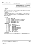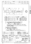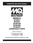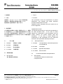
1
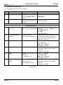
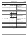
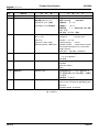
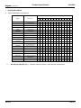
10808-5864
Product Specification
製品規格
16MAY08 Rev. A
マイクロ モータ コネクタ (Micro Motor Connector)
1. 適用範囲
1 Scope :
1.1 内容
1.1 Contents
本規格は、マイクロ・モータ・コネクタの製品性能、
This specification covers the requirements for product
試験方法、品質保証の必要条件を規定している。
performance,
適用製品名と型番は附表1の通りである。
provisions of Micro Motor connector.
test
methods
and
quality
assurance
Applicable product description and part numbers are as
shown in Appendix 1.
2. 参考規格類
Applicable Documents:
以下規格類は本規格中で規定する範囲内に於いて、本規格 The following documents form a part of this specification to
の一部を構成する。万一本規格と製品図面の間に不一致が the extent specified herein. In the event of conflict
生じた時は、製品図面を優先して適用すること。万一本規 between the requirements of this specification and the
格と参考規格類の間に不一致が生じた時は、本規格を優先 product drawing, the product drawing shall take
して適用すること。
precedence.
In the event of conflict between the
requirements of this specification and the referenced
documents, this specification shall take precedence.
2.1
AMP 規格
A. 109-5000
: 試験法の一般条件
B. 501-5502
: 試験報告書
C. 114-5335
: 取付適用規格
D. 411-78082 : 取扱説明書
2.1
A. 109-5000
Test Specification, General Requirements
for Test Methods
B. 501-5502
Test Report
C. 114-5335
Application Specification
D. 411-78082
Instructio Sheet
2.2 民間団体規格
2.2
A.
A.
MIL-STD-202
電子電気部品の試験方法
AMP Specifications :
Commercial Standards and Specifications :
MIL-STD-202
Test Methods for Electronic and Electrical
Component Parts.
タイコ エレクトロニクス アンプ株式会社 (〒213-8535 川崎市高津区久本 3-5-8)
1 of 11
Tyco Electronics Corporation (3-5-8 Hisamoto Takatsu-ku Kawasaki, 213-8535)
この文書の改版の確認は本社、支店へお問い合わせください。 This document is subject to change. Call local AMP for the latest revision.
© Copyright 2008 by Tyco Electronics Corporation All rights reserved.
* : 商標 Trademark
Released per EC FJD0-0346-03
Product Specification
108-5864
3.
一般必要条件
3. Requirements :
3.1
設計と構造
3.1
Design and Construction :
製品は該当製品図面に規定された設計、構造、物理的寸法 Product shall be of the design, construction and physical
をもって製造されていること。
dimensions specified on the applicable product drawing.
材 質
3.2
3.2
Materials :
A.コンタクト
(1) 材質 リン青銅
(2)表面処理
接触部:金めっき0.2μm以上
下 地:ニッケルめっき1.3μm以上
A. Contact
(1) Material Phos-Pho Bronze
(2) Finish
Contact area : Gold Plated 0.2μmMIN
Underplate : Nickel Plated 1.3μmMIN
B.プラグハウジング
(1)材質 熱可塑性ポリアミド
B. Plug Housing
(1) Material Polyamide of Thermoplasticity
(UL94V-0)
(UL94V-0)
C.コネクタケース
(1)材質 ガラス入り熱可塑性ポリエステル
(UL94V-0)
(1) Material Polyester containing glass of
Thermoplasticity
(UL94V-0)
D.パッキン
(1)材質 ニトリルゴム
E.グランドクリップ
(1)材質 冷間圧延鋼
(2) 表面処理
仕上げ:ニッケルめっき 2μm 以上
下地 :銅めっき 1.3μm 以上
定 格
3.3
C. Connector Case
D. Packing
(1)Material Nitorile Rubber
E. Ground Clip
(1) Material Cold-reduced carbon steel
(2) Finish
Finish plate:Nickel Plated 2μmMIN
Underplate : Copper Plated 1.3μmMIN
3.3
Ratings :
A.
定格電圧
10VAC rms
A. Voltage Rating :
B.
定格電流
1.0 A(8極)+ GROUND
C.
使用温度範囲
-30℃~105℃
B. Current Rating :
1.0 A (8POS.)+GROUND
C. Temperature Rating :-30 °C to 105 °C
(但し、温度の上限には
10VAC rms
(Including temperature
通電による温度上昇を
rising)
含む)
保護等級
D.
IP67
適用電線
3.4
仕上がり外径:φ6.8~φ7.4mm
2
導体断面積 :0.13~0.33 mm
被覆外径
:φ1.2mmMAX
3.5
性能必要条件と試験方法
製品は Fig. 1 に規定された電気的、機械的、及び耐環境的
D. DEGREES OF PROTECTION : IP67
3.4
Applicable Wire
Finish Diameter :φ6.8~φ7.4mm
2
Wire Size
: 0.13~0.33 mm
Wire insulation :φ1.2mmMAX
3.5 Performance Requirements and Test Descriptions :
The product shall be designed to meet the electrical,
性能必要条件に合致するよう設計されていること。試験は mechanical and environmental performance requirements
特別に規定されない限り室温下で行われること。
specified in Fig. 1. All tests shall be performed in the room
temperature, unless otherwise specified.
Rev. A
2 of 11
Product Specification
108-5864
3.6 性能必要条件と試験方法の要約
3.6 Test Requirements and Procedures Summary
項目
試験項目
Para.
Test Items
3.6.1
製品の確認
規
格
値
試
Requirements
験
方
法
Procedures
製品図面とAMP取付適用規格
目視により、コネクタの機能上支障をきたす
114-5303の必要条件に合致して
損傷を検査する。
いること。
3.6.1
Examination of Product
Meets requirements of product
Visual inspection
drawing and AMP Specification
No physical damage
114-5303
電 気 的 性 能
Electrical Requirements
3.6.2
総合抵抗
10 mΩ 以下 (初期)
ハウジングに組み込まれ嵌合したコンタクト
(ローレベル)
500 mΩ 以下 (GROUND初期)
を開路電圧 20 mV 以下、閉路電流 10 mA
以下の条件で測定する。
Fig. 3参照。
AMP 規格 109-5311-1
3.6.2
Termination Resistance
10 mΩ Max. (Initial)
Subject mated contacts assembled in housing
(Low Level)
500 mΩ Max. (Ground Initial)
to closed circuit current of 10 mA Max. at
open circuit voltage of 20mV Max. Fig. 3
AMP Spec. 109-5311-1
3.6.3
絶縁抵抗
500MΩ 以上
500 V DC 印加。
コネクタ嵌合あり
隣接コンタクト間で測定。
AMP 規格 109-5302-4
3.6.3
Insulation Resistance
500MΩ Min.
Impressed voltage 500 V DC.
Test between adjacent circuits of mated
connectors.
AMP Spec. 109-5302-4
3.6.4
耐電圧
沿面放電、フラッシュオーバー等 500VAC 1 分間印加
がないこと。
コネクタ嵌合 あり
リーク電流 5mA 以下
隣接コンタクト間で測定。
AMP 規格 109-5301
3.6.4
Dielectric withstanding
No creeping discharge nor
500VAC for 1 minute.
Voltage
flashover shall occur.
Test between adjacent circuits of mated
Current leakage :5mA Max.
connectors.
AMP Spec. 109-5301
Fig. 1 (続く)
Fig.1 (CONT.)
Rev. A
3 of 11
Product Specification
項目
試験項目
Para.
Test Items
3.6.5
温度上昇
規
格
値
108-5864
試
Requirements
験
方
法
Procedures
定格電流を通電して、温度上昇は 通電による温度上昇を測定すること。
30℃以下
Fig. 4参照
AMP 規格 109-5310-2
3.6.5
Temperature Rising
30℃ Max.Under loaded rating
Measure temperature rising by energized
current.
Current.
Fig. 4
AMP SPEC 109-5310-2
機 械 的 性 能
Mechanical Requirements
3.6.6
圧着部引張強度
電線サイズ
2
mm
3.6.6
3.6.7
Crimp Tensile Strength
リセコンタクト装着力
引張り強度
N(kgf)以上
AWG
0.13
#26
17.7(1.81)
0.20
#24
31.2(3.18)
0.33
#22
48.9(4.99)
Wire Size
Crimp Tensile
圧着したコンタクトを試験機に固定し、軸方
向引張力を電線に加える。操作速度は25mm/分
AMP規格 109-5205
Apply an axial pull-off load to crimped wire of
mm
2
AWG
0.13
#26
17.7(1.81)
Operation Speed : 25 mm/min.
0.20
#24
31.2(3.18)
AMP Spec. 109-5205
0.33
#22
48.9(4.99)
N(kgf)Min.
contact secured on the tester,
11.76N(1.2kgf) 以下
コンタクトをハウジングに装着するに要する
1コンタクト当り
力を測定すること。
操作速度 : 25 mm/分
3.6.7
Rec. Contact Insertion
11.76N(1.2kgf) Max.
Measure the force required to insert contact
Force
per contact
into housing.
Operation Speed : 25 mm/min.
3.6.8
3.6.8
3.6.9
3.6.9
リセコンタクト保持力
14.7N(1.5kgf) 以上
コンタクト引抜力を軸方向に加えると。
1コンタクト当り
操作速度 : 25 mm/分
Rec. Contact Retention
14.7N(1.5kgf) Min.
Apply an axial pull-off load to crimped wire.
Force
per contact
Operation Speed : 25 mm/min.
ポストコンタクト保持力
7.84N(0.8kgf) 以上
コンタクト引抜力を軸方向に加えると。
1コンタクト当り
操作速度 : 25 mm/分
Post Contact Retention
7.84N(0.8kgf) Min.
Apply an axial pull-off load to crimped wire.
Force
per contact
Operation Speed : 25 mm/min.
Fig. 1 (続く)
Fig. 1 (CONT.)
Rev. A
4 of 11
Product Specification
項目
試験項目
Para.
3.6.10
Test Items
コネクタ挿入力
規
格
108-5864
値
試
Requirements
初回:29.4N(3.0kgf)以下
験
方
法
Procedures
操作速度25 mm/分
挿入に要する力を測定
AMP 規格 109-5206
3.6.10
Connector Mating Force
Initial: 29.4 N (3.0 kgf)Max.
Operation Speed : 25 mm/min.
Measure the force required to mate
connectors.
AMP Spec. 109-5206
3.6.11
コネクタ引抜力
初回 :3.92 N(0.4 kgf)以上
操作速度25 mm/分
引抜に要する力を測定
AMP 規格 109-5206
3.6.11
Connector Unmating Force
Initial: 3.92 N( 0.4 kgf)Min.
Operation Speed : 25 mm/min.
Measure the force required to unmate
connectors.
AMP Spec. 109-5206
3.6.12
3.6.12
耐久性
⊿R=20 mΩ 以下 (終期)
挿抜回数 100 回
(繰り返し挿抜)
⊿R=500mΩ 以下(GRND終期)
AMP 規格 109-5213
Durability
⊿R=20 mΩ Max. (Final)
No. of Cycles : 100 cycles.
(Repeated Mating /
⊿R=500 mΩMax. (GRND Final)
AMP Spec. 109-5213
Unmating)
3.6.13
振動
振動中 1 μsec. をこえる不連続 嵌合したコネクタに 1.5 mm の振幅で、
(高周波)
導通を生じないこと。
10-500-10 Hz に15分毎 1 サイクルの割合で
⊿R=20 mΩ 以下 (終期)
変化する掃引振動を直交する三方向軸に 3 時
⊿R=500mΩ 以下(GRND終期)
間ずつ与えること。
100 mA を通電。
Fig.5参照
AMP 規格 109-5202 条件A
3.6.13
Vibration
No electrical discontinuity greater
Subject mated connectors to 10-500-10Hz
(High Frequency)
than 1 μsec. Shall occur.
traversed in 15 minute at 1.5 mm amplitude
⊿R=20 mΩ Max. (Final)
3 hours each of 3 mutually perpendicular
⊿R=500 mΩMax. (GRND Final)
planes.
100 mA applied.
Fig.5
AMP Spec. 109-5202 Condition A
Fig. 1 (続く)
Fig. 1 (CONT.)
Rev. A
5 of 11
Product Specification
項目
試験項目
Para.
3.6.14
Test Items
衝撃
規
格
値
108-5864
試
Requirements
験
方
法
Procedures
衝撃により1 μsec. をこえる不
加速度
: 490 m/s2 ( 50 G)
連続導通を生じないこと。
衝撃パルス波型
: 半波正弦波
⊿R=20 mΩ 以下 (終期)
接続時間 : 11 m sec.
⊿R=500mΩ 以下(GRND終期)
速度変化 : 3.4 m/s
衝撃回数 : X, Y, Z 軸正逆方向に各3 回宛、
合計 18 回
AMP 規格 109-5208 条件A
3.6.14
Physical Shock
2
No electrical discontinuity greater
Accelerated Velocity :490 m/s ( 50 G)
than 1 μsec.
Waveform
shall occur.
Duration : 11 m sec.
⊿R=20 mΩ Max. (Final)
Velocity Change
: 3.4 m/s
⊿R=500 mΩMax. (GRND Final)
Number of Drops
: 3 drops each to normal
: Half sine curve
and reversed directions of X, Y and Z axes,
totally 18 drops.
AMP Spec. 109-5208 Condition A
3.6.15
防水性
気泡が出ないこと
0.04Mpaで10分間、圧縮空気を加える。
(IP67を包含する。)
Fig.6参照
3.6.15
Water Resistance
No air hole shell be occurred
Apply compressed air for 10 minutes by
0.04Mpa
(IP67 is included.)
Fig.6
3.6.16
電線保持力
98N(10kgf)以上
適用電線を使用したコネクタを組み立てた
後、適切な治具にコネクタを固定し、電線を
引っ張る。
操作速度 : 25 mm/分
3.6.16
Wire Retention Force
98N(10kgf) Min.
After assembling connectors of applicable
wires, mount connectors to applicable jig and
pull wires
Operation Speed : 25 mm/min.
Fig. 1 (続く)
Fig. 1 (CONT.)
Rev. A
6 of 11
Product Specification
108-5864
環 境 的 性 能
Environmental Requirements
項目
試験項目
Para.
Test Items
3.6.17
熱衝撃
規
格
値
試
Requirements
験
方
法
Procedures
⊿R=20 mΩ 以下 (終期)
嵌合したコネクタ
⊿R=500mΩ 以下(GRND終期)
-40℃/ 30 分、105℃/ 30 分
移し換え時間 5分以内
これを 1サイクルとし100サイクル行う。
AMP 規格 109-5103
3.6.17
Thermal Shock
条件 H
⊿R= 20 mΩ Max. (Final)
Mated connector
⊿R=500 mΩMax. (GRND Final)
-40℃/30 min.,105℃/30min.
Shift time 5min MAX
Making this a cycle, repeat 100 cycles.
AMP spec.109-5103 Condition H
3.6.18
温湿度サイクリング
絶縁抵抗 500MΩ 以上(終期)
⊿R=20 mΩ 以下 (終期)
⊿R=500mΩ 以下(GRND終期)
嵌合したコネクタ 25~65°C,
90~95 % R. H. 10 サイクル
-10℃ 寒冷衝撃を実施する。
AMP 規格 109-5106
3.6.18
Humidity-Temperature
Cycling
3.6.19
工業ガス (SO2)
Insulation resistance
500MΩ Min. (final)
Mated connector, 25~65℃,
90~95 % R. H. 10 cycles
⊿R=20 mΩ Max. (Final)
Cold shock -10℃ performed
⊿R=500 mΩMax. (GRND Final)
AMP Spec. 109-5106
⊿R=20 mΩ 以下 (終期)
嵌合したコネクタ
⊿R=2000mΩ 以下(GRND終期)
SO2 ガス 10 ppm, 90~95 % R. H.
25°C, 96 時間
AMP 規格 109-5107
3.6.19
Industrial Gas (SO2)
⊿R=20 mΩ Max. (Final)
⊿R=2000mΩMax.(GRND Final)
条件 C
Mated connector
SO2 Gas : 10 ppm, 90~95 % R. H.
25°C, 96 hours
AMP Spec. 109-5107
3.6.20
温度寿命 (耐熱)
⊿R=20 mΩ 以下 (終期)
⊿R=500mΩ 以下(GRND終期)
Condition C
嵌合したコネクタ
105°C、期間 250時間
AMP 規格 109-5104-3 条件 C
3.6.20
Temperature Life
⊿R=20 mΩ Max. (Final)
Mated connector
(Heat Aging)
⊿R=500 mΩMax. (GRND Final)
105°C, Duration :250hours
AMP Spec. 109-5104-3 Condition C
Fig. 1 (終り)
Fig. 1 (End)
Rev. A
7 of 11
Product Specification
108-5864
4. 製品認定試験の試験順序
4. Product Qualification Test Sequence
試験グループ/Test Group
試験項目
Test Examination
1
2
3
4
5
6
7
8
9
10
11
12
13
試験順序/Test Sequence (a)
製品の確認検査
Examination of Product
総合抵抗 (ローレベル)
Termination Resistance
(Low Level)
絶縁抵抗
Insulation Resistance
2
耐電圧
Dielectric withstanding Voltage
3
温度上昇
Temperature Rising
1,4 1,3
1
1
1
1,7 1,7 1,5 1,8 1,5 1,5 1,3 1,3
2,6 2,4,6 2,4 2,5 2,4 2,4
3,6
7
2
圧着部引張強度
Crimp Tensile Strength
リセコンタクト装着力
Rec. Contact Insertion Force
2
リセコンタクト保持力
Rec. Contact Retention Force
3
ポストコンタクト保持力
Post Contact Retention Force
コネクタ挿入力
Connector Mating Force
3
コネクタ引抜力
Connector Unmating Force
4
耐久性 (繰り返し挿抜)
Durability
5
2
2
(Repeated Mate/Unmating)
振動 (高周波)
Vibration (High Frequency)
5
衝撃
Physical Shock
3
熱衝撃
Thermal shock
温湿度サイクリング
Temperature Humidity Cycling
工業ガス (SO2)
Industrial SO2 Gas
温度寿命 (耐熱)
Temperature Life (Heat Aging)
防水性
Water Resistance
電線保持力
Wire Retention Force
3
4
3
3
2
2
Fig. 2
(a)
欄内の数字は試験の順序を示す。/Numbers indicate sequence in which the tests are performed.
Rev. A
8 of 11
Product Specification
108-5864
Fig.3 ローレベル総合抵抗測定
Fig.3 Low Level Rent
Fig.4 温度上昇測定
Fig.4 Temperature Rising Measurement
Rev. A
9 of 11
Product Specification
108-5864
Fig.5 振動(高周波)試験
Fig.5 Vibration (High Frequency) Test
Fig.6 防水性測定
Fig.6 Water Resistance Measurement
Rev. A
10 of 11
Product Specification
108-5864
適用製品名と型番は附表 1 の通りである。
The applicable product descriptions and part numbers are as shown in Appendix. 1.
型番
Product Part No.
1674320-1
1674320-2
1674336-1
2040302-1
品
名
Description
エンコーダ ケーブル I/O キット マイクロ・モータ・コネクタ
ENCODER CABLE I/O KIT, MICRO MOTOR CONNECTOR
ポスト ベース ウィズ インサーション スクリュー マイクロ・モータ・コネクタ
POST BASE WITH INSETION SCREW, MICRO MOTOR CONNECTOR
ワイヤ ハーネス 1.5VP&1.0VP コネクタ
1674338-1
(1.0VPおよびモレックスコンタクトは適用外)
1871186-1
WIRE HARNESS,1.5VP&1.0VP CONNECTOR
1871186-2
(1.0VP and Molex Contact were INAPPLICABLE)
1674335-4
リセ コンタクト マイクロ・モータ・コネクタ
REC. CONTACT, MICRO MOTOR CONNECTOR
附表 1
Appendix 1
Rev. A
11 of 11