1
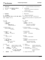
108-78417
Product Specification
製品規格
29JUL10
Rev. B
マルチプル エンクロージャ コネクタ D1000タイプ (Multiple Enclosure Connector D1000 Type)
1. 適用範囲
1
Scope :
1.1 内容
1.1 Contents
本規格は、マルチプル・エンクロージャ・コネクタ D1000 タ This specification covers the requirements for product
イプの製品性能、試験方法、品質保証の必要条件を規定し performance, test methods and quality assurance
ている。
provisions of Multiple Enclosure connector D1000
適用製品名と型番は附表1の通りである。
Type.
Applicable product description and part numbers are as
shown in Appendix 1.
2. 参考規格類
Applicable Documents:
以下規格類は本規格中で規定する範囲内に於いて、本規 The following documents form a part
格の一部を構成する。万一本規格と製品図面の間に不一 specification to the extent specified herein.
致が生じた時は、製品図面を優先して適用すること。万一 event of conflict between the requirements
本規格と参考規格類の間に不一致が生じた時は、本規格 specification and the product drawing, the
を優先して適用すること。
drawing shall take precedence.
of
this
In the
of this
product
In the event of conflict
between the requirements of this specification and the
referenced documents, this specification shall take
precedence.
2.1 AMP 規格
2.1
A.
109-5000
:
試験法の一般条件
B.
501-5913
:
試験報告書
C.
114-5377
:
D1コンタクト取付適用規格
D.
411-78262
:
取扱説明書
E.
411-78277
:
取扱説明書(R-Type)
ダイナミックコネクタ
F. 108-78268 :
D1000シリーズ製品規格
G.
114-5148
H. 108-5349
:
A. 109-5000
D3000シリーズ製品規格
I.
411-78287
:
取扱説明書(14+1Pos. Rec-Type)
J.
411-78288
:
取扱説明書(14+1Pos. Tab-Type)
Test Specification, General
Requirements for Test Methods
B. 501-5913
Test Report
C. 114-5377
D1 Contact Application Specification
D. 411-78262
Instructio Sheet
E. 411-78277
Instructio Sheet(R-Type)
F. 108-78268
Dynamic Connector
D1000 Series Product Spec.
D3コンタクト取付適用規格
ダイナミックコネクタ
:
AMP Specifications :
G. 114-5148
D3 Contact Application Specification
H. 108-5349
Dynamic Connector
D3000 Series Product Spec.
I. 411-78262
Instructio Sheet(14+1Pos. Rec-Type)
J. 411-78277
Instructio Sheet(14+1Pos. Tab-Type)
タイコ エレクトロニクス ジャパン合同会社 (〒213-8535 川崎市高津区久本 3-5-8)
Tyco Electronics Japan G.K. (3-5-8 Hisamoto Takatsu-ku Kawasaki, 213-8535)
この文書の改版の確認は本社、支店へお問い合わせください。 This document is subject to change. Call local TE for the latest revision.
© Copyright 2007-2010 by Tyco Electronics Japan G.K. All rights reserved.
* : 商標 Trademark
1 of 13
Product Specification
2.2 民間団体規格
2.2
A.
MIL-STD-202 :電子電気部品の試験方法
B
IEC.512
Commercial Standards and Specifications :
A.
MIL-STD-202
試験法規格
:
108-78417
Test Methods for Electronic and Electrical
Component Parts.
B.
3. 一般必要条件
3.1
IEC 512 Test Specification
3.
設計と構造
Requirements :
3.1
Design and Construction :
製品は該当製品図面に規定された設計、構造、物理的寸
Product shall be of the design, construction and
法をもって製造されていること。
physical dimensions specified on the applicable product
drawing.
3.2 材 質
3.2
A.コンタクト
(1)材質 銅合金
(2)表面処理
接触部:金めっき
下 地:ニッケルめっき
B.コネクタハウジング
(1)材質 熱可塑性ポリアミド
Materials :
A. Contact
(1) Material Copper alloy
(2) Finish
Contact area : Gold Plated
Underplate : Nickel Plated
B. Connector Housing
(1) Material
Polyamide of Thermoplasticity
(UL94V-0)
(UL94V-0)
C.コネクタケース
(1)材質
亜鉛
(2)表面処理 ニッケルめっき
C. Connector Case
D.パッキン
D. Packing
(1)材質 ニトリルゴム
Zinc
(2) Finish
Nickel Plated
(1) Material
E.シールドクリップ
(1)材質 冷間圧延鋼
(2)表面処理
仕上げ:ニッケルめっき
下地 :銅めっき
3.3 定 格
125VAC rms(2mm ピッチ品)
A.
250VAC rms(2.5mm ピッチ品)
B.
定格電流
Fig.1 参照
C.
使用温度範囲
-30℃~105℃
Rev. B
IP67
125VAC rms(2mm pitch)
B. Current Rating :
See Fig.1
C. Temperature Rating :-30 °C to 105 °C
(Including temperature
による温度上昇を含む)
保護等級
Ratings :
Voltage Rating :
250VAC rms(2.5mm pitch)
(但し、温度の上限には通電
D.
Nitorile Rubber
E. Shield Clip
(1) Material Cold-reduced carbon steel
(2) Finish
Finish plate:Nickel Plated
Underplate : Copper Plated
3.3
定格電圧
A.
(1) Material
rising)
D.
Degrees of Protection : IP67
2 of 13
Product Specification
3.4
3.4 適用ケーブル
108-78417
Applicable Cable
Finish Diameter : φ10~φ11mm
仕上がり外径:φ10~φ11mm
単位 Unit : A
コンタクト
Contact
タブ・コンタクト および リセ ・ コンタクト :
Tab Contact and Rec. Contact :
電線サイズ
Wire Size
AWG #18
AWG #20
AWG #22
AWG #24
AWG #26
AWG #28
AWG #30
24Pos.
-
-
2
1.5
1
0.8
0.5
15Pos.
3.5
2.7
2.5
2
1.5
1
0.8
極数
Pos.
Fig. 1
3.5
性能必要条件と試験方法
製品は Fig.2 に規定された電気的、機械的、及び耐環境的
性能必要条件に合致するよう設計されていること。試験は
特別に規定されない限り室温下で行われること。
Rev. B
3.5 Performance Requirements and Test Descriptions :
The product shall be designed to meet the electrical,
mechanical and environmental performance
requirements specified in Fig.2. All tests shall be
performed in the room temperature unless otherwise
specified.
3 of 13
Product Specification
108-78417
3.6 性能必要条件と試験方法の要約
3.6
Test Requirements and Procedures Summary
項目
試験項目
Para.
Test Items
3.6.1
製品の確認
規
格
値
試
Requirements
験
方
法
Procedures
製品図面とAMP取付適用規格
目視により、コネクタの機能上支障をきたす損
114-5337の必要条件に合致して
傷を検査する。
いること。
3.6.1
Examination of Product
Meets requirements of product
Visual inspection
drawing and AMP Specification
No physical damage
114-5337
電 気 的 性 能
Electrical Requirements
3.6.2
総合抵抗
10 mΩ 以下 (初期)
ハウジングに組み込まれ嵌合したコンタクトを
(ローレベル)
20 mΩ 以下 (終期)
開路電圧 20 mV 以下、閉路電流 10 mA
以下の条件で測定する。
Fig. 6参照。
EIA364-23
3.6.2
Termination Resistance
10 mΩ Max. (Initial)
Subject mated contacts assembled in
(Low Level)
20 mΩ Max. (Final)
housing to closed circuit current of 10 mA
Max. at open circuit voltage of 20mV Max.
Fig. 6
EIA-364-23
3.6.3
絶縁抵抗
1,000MΩ 以上(初期)
500 V DC 印加。
100MΩ 以上(終期)
コネクタ嵌合あり
隣接コンタクト間で測定。
EIA-364-21
3.6.3
Insulation Resistance
1,000MΩ Min. (Initial)
Impressed voltage 500 V DC.
100MΩ Min. (Final)
Test between adjacent circuits of mated
connectors.
EIA-364-21
3.6.4
耐電圧
沿面放電、フラッシュオーバー等
1,000VAC(2mmピッチ)、1,500VAC(2.5mm
がないこと。
ピッチ)、1 分間印加
リーク電流 0.5mA 以下
コネクタ嵌合 あり
隣接コンタクト間で測定。
EIA-364-20
3.6.4
Dielectric withstanding
No creeping discharge nor
1,000VAC(2mm pitch),1,500VAC(2.5mm
Voltage
flashover shall occur.
pitch) for 1 minute.
Current leakage :0.5mA Max.
Test between adjacent circuits of mated
connectors.
EIA-364-20
Fig. 2 (続く)
Fig.2 (CONT.)
Rev. B
4 of 13
Product Specification
項目
試験項目
Para.
Test Items
3.6.5
温度上昇
規
格
値
108-78417
試
Requirements
験
方
法
Procedures
定格電流を通電して、温度上昇
通電による温度上昇を測定すること。
は30℃以下
Fig. 1参照
EIA-364-70
3.6.5
Temperature Rising
30℃ Max. Under loaded rating
Measure temperature rising by energized
current.
current.
Fig. 1
EIA-364-70
機 械 的 性 能
Mechanical Requirements
3.6.6
コンタクト装着力
7.84N(0.8kgf) 以下
コンタクトをハウジングに装着するに要する力
1コンタクト当り
を測定すること。
操作速度 : 25 mm/分
3.6.6
Contact Insertion Force
7.84N(0.8kgf) Max.
Measure the force required to insert
per contact
contact into housing.
Operation Speed : 25 mm/min.
3.6.7
コンタクト保持力
14.7N(1.5kgf) 以上
コンタクト引抜力を軸方向に加えること。
1コンタクト当り
EIA-364-29
操作速度 : 25 mm/分
3.6.7
Contact Retention Force
14.7N(1.5kgf) Min.
Apply an axial pull-off load to crimped wire.
per contact
EIA-364-29
Operation Speed : 25 mm/min.
Fig. 2 (続く)
Fig. 2 (CONT.)
Rev. B
5 of 13
Product Specification
項目
試験項目
Para.
Test Items
3.6.8
コネクタ挿入力
規
格
108-78417
値
試
Requirements
39.2N(4.0kgf)以下
験
方
法
Procedures
操作速度25 mm/分
挿入に要する力を測定
EIA-364-13
3.6.8
Connector Mating Force
39.2 N (4.0 kgf) Max.
Operation Speed : 25 mm/min.
Measure the force required to mate
connectors.
EIA-364-13
3.6.9
コネクタ引抜力
4.9 N(0.5 kgf)以上
操作速度25 mm/分
引抜に要する力を測定
EIA-364-13
3.6.9
Connector Unmating
4.9 N( 0.5 kgf) Min.
Force
Operation Speed : 25 mm/min.
Measure the force required to unmate
connectors.
EIA-364-13
3.6.10
耐久性
(繰り返し挿抜)
コネクタ挿入力:
39.2N(4.0kgf)以下
コネクタ引き抜き力:
操作速度25 mm/分
挿抜回数 50 回
EIA-364-9
4.9 N(0.5 kgf)以上
3.6.10
Durability
(Repeated Mating /
Unmating)
Connector Mating Force:
39.2 N (4.0 kgf) Max.
Connector Unmating Force:
Operation Speed : 25 mm/min.
No. of Cycles : 50 cycles.
EIA-364-9
4.9 N( 0.5 kgf) Min.
3.6.11
振動
振動中 1 μsec. をこえる不連
嵌合したコネクタに 1.5 mm の振幅で、
(高周波)
続導通を生じないこと。
10-500-10 Hz に15分毎 1 サイクルの割合
で変化する掃引振動を直交する三方向軸に
3 時間ずつ与えること。
100 mA を通電。
EIA-364-28 試験条件2
3.6.11
Vibration
No electrical discontinuity
Subject mated connectors to 10-500-10Hz
(High Frequency)
greater than 1 μsec. Shall
traversed in 15 minute at 1.5 mm
occur.
amplitude
3 hours each of 3 mutually perpendicular
planes.
100 mA applied.
EIA-364-28 Test condition 2
Fig. 2 (続く)
Fig. 2 (CONT.)
Rev. B
6 of 13
Product Specification
項目
試験項目
Para.
3.6.12
Test Items
衝撃
規
格
値
108-78417
試
験
Requirements
方
法
Procedures
2
衝撃により1 μsec. をこえる不
加速度
:
連続導通を生じないこと。
衝撃パルス波型
: 半波正弦波
490 m/s ( 50 G)
接続時間 :
11 m sec.
速度変化 :
3.4 m/s
衝撃回数 :
X, Y, Z 軸正逆方向に各3 回
宛、合計 18 回
EIA-364-27 試験法A
3.6.12
Physical Shock
2
No electrical discontinuity
Accelerated Velocity :490 m/s ( 50 G)
greater than 1 μsec.
Waveform
shall occur.
Duration : 11 m sec.
Velocity Change
: Half sine curve
: 3.4 m/s
Number of Drops : 3 drops each to
normal and reversed directions of X, Y and
Z axes, totally 18 drops.
EIA-364-27 Method A
3.6.13
エンクロージャ・ロック強度
98N(10kgf)以上
エンクロージャのロック強度を測定
操作速度 : 25 mm/分
EIA-364-98
3.6.13
Enclosure Locking
98N(10kgf) Min.
Strength
Measure enclosure locking strength.
Operation Speed : 25 mm/min.
EIA-364-98
Fig. 2 (続く)
Fig. 2 (CONT.)
Rev. B
7 of 13
Product Specification
108-78417
環 境 的 性 能
Environmental Requirements
項目
試験項目
Para.
Test Items
3.6.14
熱衝撃
規
格
値
試
Requirements
験
方
法
Procedures
コネクタの機能上支障をきたす損
嵌合したコネクタ
傷なきこと。
-55℃/ 30 分、85℃/ 30 分
これを 1サイクルとし100サイクル行う。
EIA-364-32
3.6.14
Thermal Shock
There must not be damage that
Mated connector
interferes on the function of the
-55℃/30 min.,85℃/30min.
connector.
Making this a cycle, repeat 100 cycles.
EIA-364-32
3.6.15
温湿度サイクリング
コネクタの機能上支障をきたす損
嵌合したコネクタ 25~65°C,
傷なきこと。
90~95 % R. H. 10 サイクル
-10℃ 寒冷衝撃を実施する。
EIA-364-31
3.6.15
Humidity-Temperature
There must not be damage that
Mated connector, 25~65℃,
Cycling
interferes on the function of the
90~95 % R. H. 10 cycles
connector.
Cold shock -10℃ performed
EIA-364-31
3.6.16
工業ガス (SO2)
コネクタの機能上支障をきたす損
嵌合したコネクタ
傷なきこと。
SO2 ガス 10 ppm, 90~95 % R. H.
25°C,
3.6.16
3.6.17
Industrial Gas (SO2)
温度寿命 (耐熱)
96 時間
There must not be damage that
Mated connector
interferes on the function of the
SO2 Gas : 10 ppm, 90~95 % R. H.
connector.
25°C,
コネクタの機能上支障をきたす損
嵌合したコネクタ
傷なきこと。
96 hours
105°C、期間 96時間
EIA-364-17
3.6.17
3.6.18
Temperature Life
There must not be damage that
Mated connector
(Heat Aging)
interferes on the function of the
105°C, Duration :96hours
connector.
EIA-364-17
気泡が出ないこと
0.04Mpaで10分間、圧縮空気を加える。
防水性
(IP67を包含する。)
Fig.7参照
3.6.18
Water Resistance
No air hole shell be occurred
Apply compressed air for 10 minutes by
0.04Mpa
(IP67 is included.)
Fig.7
Fig. 2 (終り)
Fig. 2 (End)
Rev. B
8 of 13
Product Specification
108-78417
4. 製品認定試験の試験順序
4.
Product Qualification Test Sequence
試験項目
試験グループ/Test Group
Test Examination
1
2
3
4
5
6
7
8
9
10 11
試験順序/Test Sequence (a)
製品の確認検査
Examination of Product
総合抵抗 (ローレベル)
Termination Resistance
(Low Level)
絶縁抵抗
Insulation Resistance
耐電圧
Dielectric withstanding
Voltage
温度上昇
Temperature Rising
コンタクト装着力
Contact Insertion Force
コンタクト保持力
Contact Retention Force
コネクタ挿入力
Connector Mating Force
コネクタ引抜力
Connector Unmating Force
耐久性 (繰り返し挿抜)
Durability
(Repeated Mate/Unmating)
振動 (高周波)
Vibration (High Frequency)
衝撃
Physical Shock
エンクロージャ
ロック強度
Enclosure Locking Strength
熱衝撃
Thermal shock
温湿度サイクリング
Temperature Humidity
Cycling
工業ガス (SO2)
Industrial SO2 Gas
温度寿命 (耐熱)
Temperature Life
(Heat Aging)
防水性
Water Resistance
1,4 1,3
1
1,5 1,6 1,3 1,3 1,6 1,3 1,3 1,3
2,5
2
2,4
3
5
2
2
3
2
3
4
3
4
2
2
3
2
2
2
Fig. 3
(a)
欄内の数字は試験の順序を示す。/Numbers indicate sequence in which the tests are performed.
Rev. B
9 of 13
Product Specification
108-78417
4.
品質保証条件
4.1
試験条件
特に指定のない場合、下記に示す環境条件のもとで性能試
験を行うものとする。
4.
Quality Assurance Provisions :
4.1
Test Conditions :
Unless otherwise specified, all the test shall be
performed in any combination of the following test
conditions.
温 度
相対湿度
気 圧
Temperature :
Relative Humidity :
Atmospheric Pressure :
15~35℃
45~75 %
86.6~106.6 Kpa
15~35℃
45~75 %
86.6~106.6 Kpa
Fig. 4
4.2
試験
4.2.1
試料
性能試験に用いる試料は、該当製品図面上の規定事項に
合致したものであること。また圧着コンタクトは『ダイナミック
コネクタ D1000 シリーズ・コンタクトの圧着条件 114-5377』
に基づいて Fig. 5 に示す電線を圧着した正規の試料であ
ること。
4.2
Tests :
4.2.1
Test Specimens :
The test specimens to be employed for the tests shall
be conforming to the requirements specified in the
applicable product drawings. The crimped contacts
shall be prepared in accordance with the requirements
of applicable application Specification, 114-5377,
Crimping of DYNAMIC CONNECTOR D1000 Series.
on the wires specified in Fig. 5 of this specification.
4.2.2
Applicable Wires :
4.2.2
使用電線
The
wires
to be used for crimping the samples for
性能試験して用いる電線は、Fig. 5 に示す電線にて行うも
performance
testing shall be conforming to the
のとする。
requirements specified in Fig. 5.
2
計算断面積(mm )
Calculated
Cross-sectional
2
Area(mm )
0.05
0.08
0.14
0.22
0.34
0.52
0.86
AWG
素線径(mm)
Diameter of a
Conductor (mm)
素線数
Number of
Conductors
絶縁被覆外径(mm)
Insulation Outer
Diameter (mm)
30
28
26
24
22
20
18
0.102
0.12
0.16
0.16
0.16
0.16
0.16
7
7
7
11
17
26
43
0.8
1.08
1.3
1.4
1.6
1.8
2.2
Fig. 5
Rev. B
10 of 13
Product Specification
108-78417
Ω=V/A
Ω
Fig.6 ローレベル総合抵抗測定
Fig.6 Termination Resistance (Low Level) Measurement
Fig.7 防水性測定
Fig.7 Water Resistance Measurement
Rev. B
11 of 13
Product Specification
108-78417
適用製品名と型番は附表 1 の通りである。
The applicable product descriptions and part numbers are as shown in Appendix. 1.
型番
品
Product Part No.
名
備考
Description
1939847-1
プラグケース Ass’y
1981560-1
Plug Case Ass’y
1939840-1
ジャックケース Ass’y
Remarks
Jack Case Ass’y
1939850-1
1981551-1
リセハウジング
Rec. Housing
1981135-1
1981945-1
1939839-1
1981556-1
タブハウジング
Tab Housing
1981133-1
1981947-1
1939851-1
シールドクリップ
Shield Clip
2
1827569-2(Reel)
D-1000 リセ コンタクト Sタイプ
AWG #30~28(0.05~0.10mm )
1827586-2(L/P)
D-1000 Rec. Contact S-Type
INSULATION RANGE φ0.6~φ1.2mm
1827570-2(Reel)
D-1000 リセ コンタクト M タイプ
AWG #28~22(0.08~0.37mm )
1827587-2(L/P)
D-1000 Rec. Contact M-Type
INSULATION RANGE φ1.08~φ1.6mm
1827571-2(Reel)
D-1000 リセ コンタクト L タイプ
AWG #28~22(0.08~0.37mm )
1827588-2(L/P)
D-1000 Rec. Contact L-Type
INSULATION RANGE φ1.08~φ1.9mm
1827572-2(Reel)
D-1000 リセ コンタクト 2Lタイプ
AWG #22~18(0.34~0.87mm )
1827588-2(L/P)
D-1000 Rec. Contact 2L-Type
INSULATION RANGE φ1.4~φ2.2mm
1903111-2(Reel)
D-1000 タブ コンタクト Sタイプ
AWG #30~28(0.05~0.10mm )
1903115-2(L/P)
D-1000 Tab Contact S-Type
INSULATION RANGE φ0.6~φ1.2mm
1903112-2(Reel)
D-1000 タブ コンタクト M タイプ
AWG #28~22(0.08~0.37mm )
1903116-2(L/P)
D-1000 Tab Contact M-Type
INSULATION RANGE φ1.08~φ1.6mm
1903113-2(Reel)
D-1000 タブ コンタクト Lタイプ
AWG #28~22(0.08~0.37mm )
1903117-2(L/P)
D-1000 Tab Contact L-Type
INSULATION RANGE φ1.08~φ1.9mm
1903114-2(Reel)
D-1000 タブ コンタクト 2Lタイプ
AWG #22~18(0.34~0.87mm )
1903118-2(L/P)
D-1000 Tab Contact 2L-Type
INSULATION RANGE φ1.4~φ2.2mm
2
2
2
2
2
2
2
附表 1(続く)
Appendix 1(CONT.)
Rev. B
12 of 13
Product Specification
型番
Product Part No.
品
名
108-78417
備考
Description
Remarks
2
175194-2(Reel)
D-3000 リセ コンタクト Sタイプ
AWG #28~24(0.08~0.20mm )
175216-2(L/P)
D-3000 Rec. Contact S-Type
INSULATION RANGE φ1.04~φ1.43mm
175195-2(Reel)
D-3000 リセ コンタクト M タイプ
AWG #24~20(0.20~0.50mm )
175217-2(L/P)
D-3000 Rec. Contact M-Type
INSULATION RANGE φ1.27~φ2.56mm
175196-2(Reel)
D-3000 リセ コンタクト L タイプ
AWG #20~16(0.50~1.25mm )
175218-2(L/P)
D-3000 Rec. Contact L-Type
INSULATION RANGE φ1.80~φ2.80mm
175284-2(Reel)
D-3000 タブ コンタクト Sタイプ
AWG #28~24(0.08~0.20mm )
175287-2(L/P)
D-3000 Tab Contact S-Type
INSULATION RANGE φ1.04~φ1.43mm
175285-2(Reel)
D-3000 タブ コンタクト M タイプ
AWG #24~20(0.20~0.50mm )
175288-2(L/P)
D-3000 Tab Contact M-Type
INSULATION RANGE φ1.27~φ2.56mm
175286-2(Reel)
D-3000 タブ コンタクト Lタイプ
AWG #20~16(0.50~1.25mm )
175289-2(L/P)
D-3000 Tab Contact L-Type
INSULATION RANGE φ1.80~φ2.80mm
2
2
2
2
2
附表 1(終り)
Appendix 1(END.)
Rev. B
13 of 13