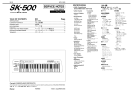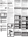
1
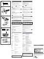
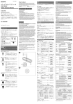
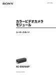
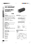
3-206-581-04 (1) カラービデオカメラモジュール CCD Color Video Camera Module Owner’s Record 日本語 The model and serial numbers are located on the outer surface. Record the serial number in the space provided below. Refer to these numbers whenever you call upon your Sony dealer regarding this product. カメラ設置上のご注意 Model No. _____________ Serial No. ______________ Operating Instructions お買い上げいただきありがとうございます。 電気製品は、安全のための注意事項を守らないと、けがをし たり周辺の物品に損害を与えることがあります。 この取扱説明書には、事故を防ぐための重要な注意事項と製品の取り扱い かたを示してあります。この取扱説明書をよくお読みのうえ、製品を安全 にお使いください。お読みになったあとは、いつでも見られるところに必 ず保管してください。 図A カメラ設置の際は、周辺機器を含めてカメラに接続されている各機器間で接 地電位の差が生じないようにしてください。接地電位差により故障の原因と なる場合があります。設置の都合により電位差を生ずる場合は、機器の内い ずれかひとつの機器だけを接地するようにしてください。 • Read these instructions. • Keep these instructions. • Heed all warnings. • Follow all instructions. • Do not use this apparatus near water. • Clean only with dry cloth. • Do not block any ventilation openings. Install in accordance with the manufacturer’s instructions. • Do not install near any heat sources such as radiators, heat registers, stoves, or other apparatus (including amplifiers) that produce heat. • Only use attachments/accessories specified by the manufacturer. • Unplug this apparatus during lightning storms or when unused for long periods of time. • Refer all servicing to qualified service personnel. Servicing is required when the apparatus has been damaged in any way, such as powersupply cord or plug is damaged, liquid has been spilled or objects have fallen into the apparatus, the apparatus has been exposed to rain or moisture, does not operate normally, or has been dropped. XC-555/555P 電源について DC+12 Vで動作します。リップル、ノイズのない安定した電源をお使いく ださい。 非常に明るい被写体(照明や太陽など)を長時間にわたって撮影しないでく ださい。CCD内のカメラフィルターが退色する原因となることがあります。 また、次のような場所での使用および保管は避けてください。 • 極端に暑い所や寒い所。適正使用温度は0∼40℃です。 • 激しい振動のある所。 • 強力な電波を発生するテレビ、ラジオの送信所の近く。 お手入れ レンズや光学フィルターの表面に付着したごみやほこりは、ブロアーで払っ てください。外装の汚れは、乾いた柔らかい布でふきとります。ひどい汚れ は、中性洗剤溶液を少し含ませた布でふきとった後、からぶきします。アル コール、ベンジンなどは、変質したり塗料がはげることがありますので、使 用しないでください。 うに充分注意してください。 Sony Corporation 2001 To reduce the risk of fire or electric shock, do not expose this apparatus to rain or moisture. Printed in Japan To avoid electrical shock, do not open the cabinet. Refer servicing to qualified personnel only. 安全のために ソニー製品は安全に充分に配慮して設計されています。しかし、まちがった 使いかたをすると、火災や感電などにより死亡や大けがなど人身事故につな がることがあり、危険です。 事故を防ぐために次のことを必ずお守りください。 • 安全のための注意事項を守る。 • 長期間、安全にお使いいただくために、定期点検をすることをおすすめ します。点検の内容や費用については、お買い上げ店にご相談ください。 • 故障したら使わずに、お買い上げ店にご連絡ください。 警告表示の意味 行為を禁止する記号 この取扱説明書および製品では、 次のよ うな表示をしています。表示の内容をよ く理解してから本文をお読みください。 行為を指示する記号 この表示の注意事項を守らないと、 火災 やその他の事故によりけがをしたり周 辺の物品に損害を与えたりすることが あります。 For the customers in the USA This device complies with Part 15 of the FCC Rules. Operation is subject to the following two conditions: (1) This device may not cause harmful interference, and (2) this device must accept any interference received, including interference that may cause undesired operation. - Reorient or relocate the receiving antenna. - Increase the separation between the equipment and receiver. - Connect the equipment into an outlet on a circuit different from that to which the receiver is connected. - Consult the dealer or an experienced radio/TV technician for help. You are cautioned that any changes or modifications not expressly approved in this manual could void your authority to operate this equipment. 下記の注意事項を守らないと、 けがをしたり周辺の物品に損害 を与えることがあります。 内部に水や異物を入れない 水や異物が入ると、火災の原因となります。 万一、水や異物が入ったときは、すぐに本機が接続され ている電源供給機器の電源を切り、D C 電源ケーブルや 接続ケーブルを抜いて、お買い上げ店にご相談くださ い。 分解しない、 改造しない 分解や改造をすると、火災やけがの原因となります。 点検および修理は、お買い上げ店にご依頼ください。 カメラケーブルを傷つけない カメラケーブルを傷つけると、火災の原因となることが あります。次の項目をお守りください。 • 設置時に、製品と壁やラック、棚などの間に、はさみ込 まない。 • カメラケーブルを加工したり、傷つけたりしない。 • 重いものをのせたり、引っ張ったりしない。 • 熱器具に近づけたり、加熱したりしない。 • カメラケーブルを抜くときは、必ずプラグを持って抜 く。 芯線の露出や断線などでカメラケーブルが傷んだら、お 買い上げ店に交換をご依頼ください。そのまま使用する と、火災の原因となります。 主な特長 XC-555は、1/2型のCCD(Charge Coupled Device)を採用した超小 型カラーカメラモジュールです。 超小型・軽量 従来のカメラよりさらに小型・軽量化されたため、今まではカメラを取り付 けられなかった場所にも設置できます。 高感度 Super HAD(Hole Accumulated Diode)センサーを搭載し、高感度、 低スミアを実現。照明条件の悪い場所でも撮影できます。 高解像度 All interface cables used to connect peripherals must be shielded in order to comply with the limits for a digital device pursuant to Subpart B of Part 15 of FCC Rules. ホワイトバランス用DIPスイッチで、3200K/5600K/ATW/MANの4種 類のホワイトバランスモードの中から、撮影条件に合った設定を選べるの で、適切な色調が得られます。 3段階の電子シャッタースピード 電子シャッター用DIPスイッチで、OFF/1/1000/FLICKERLESSの3段 階のシャッタースピードの中から、撮影条件に合った速度が選べます。 DIPスイッチをCCD IRIS機能の設定にすると、入射光量に応じて自動的に シャッタースピード調整を行い、映像信号を適正なレベルに保ちます。 各部の名称と働き 5600K (固定モード) 撮影条件(光源) DIPスイッチの設定 室内の白熱灯下での撮影に適してい ます。 (工場出荷時の設定) 1 · · · · 6 晴天の屋外での撮影に適していま す。 1 · · · · 6 ATW For the customers in Canada This Class B digital apparatus complies with Canadian ICES-003. (オートトレー シングホワイト バランス) 色温度の推移にともなってホワイト バランスが自動調整されます。撮影 の光源が朝の光から夕方の光に変化 する場合などに適しています。 Pour les utilisateurs au Canada Cet appareil numérique de la classe B est conforme à la norme NMB-003 du Canada. MAN R(赤)調整ボリュームとB(青) (マニュアル) 調整ボリュームで、赤系と青系の色 合いを調整するときにこの位置にし ます。 For the customers in Europe The manufacturer of this product is Sony Corporation, 1-7-1 Konan, Minato-ku, Tokyo, Japan. The Authorized Representative for EMC and product safety is Sony Deutschland GmbH, Hedelfinger Strasse 61, 70327 Stuttgart, Germany. Pour les clients en Europe Le fabricant de ce produit est Sony Corporation, 1-7-1 Konan, Minato-ku, Tokyo, Japon. Le représentant autorisé pour EMC et la sécurité des produits est Sony Deutschland GmbH, Hedelfinger Strasse 61, 70327 Stuttgart, Allemagne. 1 · · · · 6 1 · · · · 6 2 シャッタースピード設定 撮影条件に応じたシャッタースピードに設定します。CCD IRIS機能を使用 する場合は、CCD IRISモードに設定します。 シャッタースピード OFF DIPスイッチの設定 1/60秒 Be careful not to spill liquids, or drop any flammable or metal objects in the camera body. Locations for operation and storage Do not keep the camera aimed at very bright sources (electric lights, the sun, and so on). Doing so may cause discoloring of the CCD color filter. Also, avoid operating or storing the camera under the following conditions. • Extremely hot or cold locations. Recommended temperature range is 0°C to 40°C (32°F to 104°F). • Locations subject to strong vibration • Near generators of strong electromagnetic radiation such as TV or radio transmitters. Care Use a blower to remove dust from the surface of the lens or optical filter. Clean the exterior with a soft, dry cloth. If the camera is very grimy, apply a cloth soaked in a mild detergent then wipe with a dry cloth. Do not apply organic solvents such as alcohol or benzine which may damage the finish. Note on laser beams Features The XC-555/555P is an ultra-small color camera module that utilizes a 1/2type Charge Coupled Device. Ultra-small size and lightweight The camera is so small and light that you can install it anywhere: even in locations where conventional video cameras cannot be installed. High resolution A built-in Super HAD (Hole Accumulated Diode) sensor, allows high sensitivity, low smear images. You can shoot, even under poor lighting conditions. With a CCD offering 380,000 effective pixels, high-resolution images can be obtained. Four white balance adjustment modes Using the white balance DIP switches, you can choose from among four white balance modes (3200K/5600K/ATW/MAN) to choose the best settings for shooting conditions, and the most appropriate color compensation. Electronic shutter with a wide range of operating speeds Using the electronic shutter DIP switches, these levels of shutter speed (OFF, 1/1000, and FLICKERLESS) are available to allow you to match the shutter speed to the shooting conditions. When you set the DIP switches for the CCD IRIS function, the shutter speed is adjusted automatically, based on the amount of light allowed to enter, ensuring the most appropriate level of image signal. Location and Function of Parts 1/1000 Lighting condition For indoor shooting under incandescent light (factory setting). 3200K (fixed) ATW (auto tracing white balance) The white balance is adjusted according to the color temperature transition of the subject. This mode is suitable for shooting with variable lighting. MAN (manual) Select this position when you want to adjust the red color with the R control and the blue color with the B control. Shutter speed 1/60 sec. (factory setting) (XC-555) 1/50 sec. (factory setting) (XC-555P) 1/1000 1/1000 sec. CCD IRIS Set the CCD IRIS mode. ゲイン ON DIPスイッチの設定 オートゲインコントロール (工場出荷時の設定) 1 · · · · 6 3 AGC (auto gain control) ON/OFF 0 dB Gain GND2 設置については、必ずお買い上げ店にご相談ください。 壁面や天井などへの設置は、本機と取り付け金具を含む 重量に充分耐えられる強度があることをお確かめくだ さい。充分な強度がないと、落下して、大けがの原因とな ります。 また、1年に1度は、取り付けがゆるんでいないことを点 検してください。 Abnormal electricity GND1 4 出力信号(Y/C/VBS)切り換え カメラ出力信号を選択します。 出力信号 Y/C (接地電位差)/ Y(輝度信号)/C(色信号)分離信 VBS B この取扱説明書に記されている電源供給機器(カメラア ダプターなど)でお使いください。規定外の電源でのご 使用は、火災の原因となることがあります。 4 DC IN/SYNC/VIDEO端子(12ピン)( 図C 参照) カメラケーブルCCXC-12P02N/12P05N/12P10N/12P25Nを接続し、 DC+12Vの電源の供給を受けるとともにカメラモジュールからの映像信号を 出力します。 また、同期信号発生器を接続して外部同期信号(VS、HD/VD)を入力する と、カラーカメラモジュールを外部同期で動作させることができます。 この取扱説明書に記されているカメラケーブル、接続 ケーブルを使わないと、火災の原因となることがありま す。 信号 ピン番号 5 4 C 3 1 9 2 10 8 11 12 4 5 6 7 1 2 3 4 5 6 7 8 9 10 11 12 同期信号の種類 外部同期信号 HD,VD VS入力 GND(アース) GND(アース) 内部同期信号 GND(アース) +12V +12V +12V VBS/Y出力(アース) VBS/Y出力(アース) VBS/Y出力(アース) VBS/Y出力(信号) VBS/Y出力(信号) VBS/Y出力(信号) HD入力(アース) HD入力(信号) VS入力(信号) VD入力(信号) GND(−/C) GND(−/C) GND(−/C) −/C出力(信号) −/C出力(信号) −/C出力(信号) RS-232C(TXD)* RS-232C(RXD)* VS入力(アース) GND VD入力(アース) * RS-232Cスイッチは出荷時OFF 設定変更の詳細についてはユーザーズガイドをご覧ください。 5 レンズマウント(専用マウント) 1 · · · · 6 4 Y/C/VBS Select the camera output signal. DIP switch setting Y/C Select this position to output the Y/C separated signal from the DC IN/VIDEO connector. 1 · · · · 6 VBS Select this position to output the VBS signal from the DC IN/ VIDEO (factory setting). 1 · · · · 6 1 · · · · 6 3 B調整ボリューム 青色系調整ボリュームです。ホワイトバランス調整モードがMANに設定され ているとき動作します。 指定されたカメラケーブル、接続ケーブルを使う 0 dB Output signal 2 R調整ボリューム 赤色系調整ボリュームです。ホワイトバランス調整モードがMANに設定され ているとき動作します。 1 2 3 OFF 1 · · · · 6 VBS信号を出力するときは、この位 置にします。 (工場出荷時の設定) 指定された電源を使う Auto gain control (factory setting) DIP switch setting 1 · · · · 6 DIPスイッチの設定 号を出力するときは、この位置にし ます。 (Ground electric potential difference) ON 1 · · · · 6 カメラ / Camera 異常電流/ 1 · · · · 6 FLICKERLESS 1/100 sec. (XC-555) 1/120 sec. (XC-555P) 電源/ Power supply unit 設置は確実に DIP switch setting 1 · · · · 6 1 · · · · 6 OFF 1 · · · · 6 1 · · · · 6 1 · · · · 6 モニター/ Monitor 1 · · · · 6 2 Shutter speed Set the shutter speed switches to select the desired shutter speed. Using the CCD IRIS function, set the CCD IRIS mode. 1 · · · · 6 FLICKERLESS 1/100秒 1 · · · · 6 1 · · · · 6 1 · · · · 6 CCD IRISモードに設定します。 DIP switch setting For outdoor shooting on sunny days. 5600K (fixed) OFF 1/1000秒 Fig. B 1 Dip switches for setting functions 1 WHITE BALANCE Select the white balance setting according to the lighting conditions. 1 · · · · 6 3 AGC(オートゲインコントロール)ON/OFF A The camera operates on +12 V DC. Use a stable power source free from ripple or noise. (工場出荷時の設定) CCD IRIS Für Kunden in Europa Der Hersteller dieses Produkts ist Sony Corporation, 1-7-1 Konan, Minato-ku, Tokyo, Japan. Der autorisierte Repräsentant für EMV und Produktsicherheit ist Sony Deutschland GmbH, Hedelfinger Strasse 61, 70327 Stuttgart, Deutschland. 図B 1 各種機能設定用DIPスイッチ 1 ホワイトバランス調整 撮影条件(光源)に合わせて、次の4種類のモードに設定できます。 (固定モード) Power supply High sensitivity 4種類のホワイトバランスモード 3200K When you install the camera with various peripheral devices and if the devices have different ground electric potential, ground only one device. In case there is a ground electric potential difference, the camera may be damaged. Laser beams may damage a CCD. You are cautioned that the surface of a CCD should not be exposed to laser beam radiation in an environment where a laser beam device is used. 有効画素数が約38万画素のCCDにより、きめ細かな画像を再現します。 This equipment has been tested and found to comply with the limits for a Class B digital device, pursuant to Part 15 of the FCC Rules. These limits are designed to provide reasonable protection against harmful interference in a residential installation. This equipment generates, uses and can radiate radio frequency energy and, if not installed and used in accordance with the instructions, may cause harmful interference to radio communications. However, there is no guarantee that interference will not occur in a particular installation. If this equipment does cause harmful interference to radio or television reception, which can be determined by turning the equipment off and on, the user is encouraged to try to correct the interference by one or more of the following measures: Fig. A Foreign bodies 使用・保管場所 レーザービームについてのご注意 レーザービームはCCDに損傷を与えることがあります。レーザービーム を使用した撮影環境では、CCD 表面にレーザービームが照射されないよ WARNING When installing the camera Notes on Operation 使用上のご注意 Important Safety Instructions 取扱説明書 English 2 R control for manual white balance adjustment This control is effective when the white balance switches are set to MAN. Adjust the red color by turning the control. 3 B control for manual white balance adjustment This control is effective when the white balance switches are set to MAN. Adjust the blue color by turning the control. 4 DC IN/SYNC/VIDEO connector (multi 12-pin) (See Fig. C ) This connector inputs DC 12V power and outputs the video signal when the CCXC-12P02N/12P05N/12P10N/12P25N camera cable is connected. If the unit is connected to devices that originate a synchronized signal, the external synchronous signal (VS, HD/VD) can be used to move the color camera module. Signal Pin No. 1 2 3 4 5 6 7 8 9 10 11 12 Sync signal types External Sync signal VS Input HD,VD GND (Earth) GND (Earth) +12V +12V VBS/Y Output (Earth) VBS/Y Output (Earth) VBS/Y Output (signal) VBS/Y Output (signal) HD Input (Earth) HD Input (signal) VS Input (signal) VD Input (signal) GND (−/C) GND (−/C) −/C Output (signal) −/C Output (signal) RS-232C (TXD) * RS-232C (RXD) * VS Input (Earth) VD Input (Earth) Internal Sync signal GND (Earth) +12V VBS/Y Output (Earth) VBS/Y Output (signal) GND (−/C) −/C Output (signal) GND * The RS-232C switch is set to OFF at the factory For details on how to change this setting, please refer to the Technical Manual. 5 Lens mount (special mount) D レンズマウント面 4.1mm以下 4.1 mm or less Lens mount shoulder E • • • • • 日本語 English 設置 Installation 適応レンズ Usable Lenses スペシャルマウントレンズVCL-12S12XM(f=12mm) スペシャルマウントレンズVCL-06S12XM(f=6mm) スペシャルマウントレンズVCL-03S12XM(f=3.5mm) スペシャルマウントレンズVCL-12SXM(f=12mm) Cマウント式レンズ 1/2インチ用Cマウントレンズ(ただし、レンズマウント面からの飛び出 し量が4.1mm以下のもの)( 図D 参照)。Cマウント式レンズを取り付 ける場合は、CマウントアダプターLO-999CMTが必要です。 ご注意 • 2/3インチ用Cマウント式レンズをご使用になると、画角が変わります。 • 重いレンズをつけたときは、レンズのささえが必要です。 • 重いレンズをつけた状態で、震動や衝撃を加えないでください。 3 2 図E レンズの取り付け 1 レンズマウントキャップを回して外す。 2 Cマウント式レンズを使う場合は、Cマウントアダプターを回して取り付 ける。 • VCL-12S12XM special mount lens (f=12mm) • VCL-06S12XM special mount lens (f=6mm) • VCL-03S12XM special mount lens (f=3.5mm) • VCL-12SXM special mount lens (f=12mm) • C-mount lens Half-inch C-mount lens (It should stand out less than 4.1 mm from the lens mount shoulder) (See Fig. D ). When a C-mount type lens is attached, a C-mount adaptor (LO-999CMT) is required. Notes • This camera uses a 1/2-inch CCD. So the lens should be used with this size of CCD. If used with a lens intended for 2/3-inch CCD, the angle of view will be different. • When connecting a heavy lens, make sure that it is supported properly. • When connecting heavy lens, make sure that it is not subject to shocks or vibration. Attaching the Lens Fig. E 1 Remove the lens mount cap by turning it counterclockwise. 2 Screw the C-mount adaptor into the lens mount of the camera. (only when using a C-mount lens) 3 レンズを回して取り付ける。 3 Screw the lens. 図F 三脚への取り付け Installing the Camera on a Tripod Fig. F When mounting the camera on a tripod, use the supplied tripod adaptor. 本機を三脚に取り付けるときは、三脚用アダプター(付属)を使用します。 1 Assemble the tripod adaptor parts. 2 Mount the video camera module on the tripod adaptor. 1 三脚用アダプター(1対)を組み立てる。 2 本機を三脚用アダプターに取り付ける。 1 Note ご注意 カメラを付属の三脚用アダプターでご使用の際には振動、衝撃のある所で は使わないでください。故障の原因になります。 F 接続 図G カメラアダプターDC-700と組み合わせる場合の例です。 • 接続する機器の電源を切ってください。電源を入れたまま接続すると内 部の部品が破損するおそれがあります。 • コネクターを抜くときは、必ずプラグ部分を持って抜いてください。 ケーブルを引っ張ると断線などの原因になります。 本機は内部同期と外部同期が自動的に切り換わるようになっています。外部よ り下表に示す同期信号を入力すると、自動的に外部同期に切り換わります。 外部同期信号 HD/VD カメラ−DC-700の 接続の場合 VS ゲンロック可 VBS ゲンロック不可 CCD特有の現象 CCDカメラの場合、次のような現象が起こることがありますが、故障ではあ りません。 When you have finished installation, tighten the screws to secure the module. G Fig. G An example of the assembly of the DC-700/DC-700CE Camera Adaptor. • Make sure to turn off the power to the units you are connecting or their components may be damaged. • When disconnecting the cord, pull it out by the plug. Never pull the cord itself. • Connect the power cord after completing all other connections. Genlock ゲンロック 向きを決めてから、ネジ2本で固定します。 Connections Notes ご注意 接続例 When the camera is attached to the supplied tripod adaptor, avoid using it in locations subject to vibration or shock. 白点 CCD撮像素子は非常に精密な技術で作られていますが、宇宙線などの影響に より、まれに画面上に微小な白点が発生する場合があります。 これはCCD撮像素子の原理に起因するもので故障ではありません。 また、下記の場合、白点が見えやすくなります。 • 高温の環境で使用するとき • ゲイン(感度)を上げたとき The color video camera module is designed so that internal sync and external sync are switched automatically. When the color video camera module receives the following external sync signal, the camera is synchronized to that external sync signal. Connection example HD/VD Connection of the camera and the DC-700/DC-700CE External sync signal VS Genlock VBS No genlock CCD Characteristics The following conditions that may be observed during the use of a CCD video camera are not associated with any fault of the camera. White flecks Although the CCD image sensors are produced with high-precision technologies, fine white flecks may be generated on the screen in rare cases, caused by cosmic rays, etc. This is related to the principle of CCD image sensors and is not a malfunction. カラービデオカメラモジュール スミア Color video camera module The white flecks especially tend to be seen in the following cases: • when operating at a high environmental temperature • when you have raised the gain (sensitivity) 高輝度の被写体を写したときに、明るい帯状の縦線(垂直スミア)がモニ ター画面に見えます( 図H 参照)。 Smearing DC IN/SYNC/VIDEO端子へ to DC/IN/SYNC/VIDEO connector CCXC-12P02N/12P05N/ 12P10N/12P25N 梨地状の模様 高温の場所でカメラを動作させたとき、一定のパターンをもつ模様(ノイ ズ)が、モニター画面全体に見えます。 WEN HD 1 VIDEO 1 CAMERA AC IN 2 2 TRIG VD/SYNC Jagged picture When stripes, straight lines, or the like are shot, the image monitored on the screen may appear jagged. Specifications 撮影部 撮像素子 1/2型 色フィルター 有効画素数 インターライン転送方式CCD 補色モザイクフィルター 約38万画素(水平768×垂直494) レンズマウント 信号方式 走査方式 縦に薄く尾を引いたよ うな画像になる。 Pale stripe (smear) 同期方式 外部同期入力 水平解像度 最低被写体照度 感度 映像出力 モニター画面 Video monitor screen 高輝度の被写体 (電灯、蛍光灯、太 陽、強い反射光など) Very bright object (such as an electric lamp, florescent lamp, sunlight, or strong reflected light) This may appear over the entire monitor screen when the camera is operated at a high temperature. 縞模様、線などを写したとき、ギザギザのちらつきが見えます。 映像S/N シャッタースピード ホワイトバランス ゲインコントロール 出力端子 専用マウント(NFマウント) EIAJ標準NTSCカラー方式 走査線数525本、 2:1インターレース 毎秒30枚 内部/外部(自動切り換え) HD/VD 、VS 470TV本 3 lux(F1.2、AGC : ON) 2000 lux(F8、AGC : OFF(0 dB)) VBS/Y/C(スイッチ切り換え) VBS : 1 Vp-p、75 Ω、同期負 Y : 1 Vp-p、75 Ω C : コンポジットビデオ出力に準ずる 48 dB(標準)AGC : OFF(0 dB) 4モード : 1/60(OFF)、1/1000、CCD IRIS、フ リッカーレス 4モード : ATW、3200K、5600K、MAN 2モード : AGC、固定(0 dB) DC IN/SYNC/VIDEO端子 : 12ピン 一般 電源電圧 消費電力 使用温度 保存温度 使用湿度 保存湿度 耐振動性 耐衝撃性 DC10.5 – 15 V 2.4 W 0∼40 ℃ −30∼+60 ℃ 20∼80% (結露状態は不可) 20∼90% (結露状態は不可) 10 G(20 Hz∼200 Hz) 70 G 本体 質量 外形寸法 Pickup device Pickup device Interline transfer 1/2-type CCD Color filter Complementary color mosaic Total picture elements XC-555: 768(H) × 494(V) XC-555P: 752(H) × 582(V) Optical and others 光学系、機能 H Patterned noise 折り返しひずみ 主な仕様 DC-700 The picture may be smeared when a very bright object is shot. (See Fig. H ) 約60 g 幅22×高さ22×奥行き75 mm(突起部含まず) 付属品 レンズマウントキャップ(1) 三脚用アダプター(1対) 取扱説明書(1) Lens mount Signal system Special mount (NF mount) XC-555: NTSC standard XC-555P: PAL standard Scanning system XC-555: 525 lines, 2:1 interlace, 30 frames/sec. XC-555P: 625 lines, 2:1 interlace, 25 frames/sec. Sync system Internal/External (automatic switching) External synchronous input HD/VD, VS Horizontal resolution XC-555: 470 TV lines XC-555P: 460 TV lines Minimum illumination 3 lux at F1.2 AGC: ON Sensitivity 2000 lux at F8 AGC: OFF (0 dB) Video output VBS/Y/C (selected with the switch) VBS: 1 Vp-p, 75 ohms, sync negative Y: 1 Vp-p, 75 ohms C: C level depends on the composite video out signal Video signal to noise ratio XC-555: 48 dB (standard) AGC: OFF (0 dB) XC-555P: 46 dB (standard) AGC: OFF (0 dB) Shutter speed 4 speeds selectable: 1/60 sec. (OFF) (NTSC)/ 1/50 sec. (OFF) (PAL), 1/1000 sec., CCD IRIS, and FLICKERLESS White Balance 4 modes selectable: ATW (auto white tracing balance), 3200K, 5600K, and MAN (manual) Gain control 2 modes selectable: AGC and fixed (0 dB) Output connect DC IN/SYNC/VIDEO: multi 12-pin Power requirement 10.5 to 15 V DC Power consumption 2.4 W Operating temperature 0°C to 40°C (32°F to 104°F) Storage temperature –30°C to 60°C (–22°F to 140°F) Operating humidity 20 to 80% (no condensation permissible) Storage humidity 20 to 90% (no condensation permissible) Vibration resistance 10 G (20 Hz – 200 Hz) Shock resistance 70G Dimensions 22 × 22 × 75 (mm) (w/h/d)(7/8 × 7/8 × 2 15/16 inches) Mass 60g (2 oz) Accessories supplied Lens mount cap (1) Tripod adaptor (1 set) Operating Instructions (1) VCL-12S12XM(f=12 mm) VCL-06S12XM(f=6 mm) VCL-03S12XM(f=3.5 mm) VCL-12SXM(f=12 mm) Cマウントアダプター LO-999CMT 接写リングキット LO-999ERK ケーブル CCXC-12P02N/12P05N/12P10N/12P25N (12ピン) 仕様および外観は改良のため予告なく変更することがありますが、ご了承くださ い。 お使いになる前に、必ず動作確認を行ってください。故障その他に伴う営 業上の機会損失等は保証期間中および保証期間経過後にかかわらず、補償 はいたしかねますのでご了承ください。 この取扱説明書は本機の基本的な機能と使用方法について記載しており ます。 より詳しい情報をお知りになりたい方は「ユーザーズガイド」をご覧くだ さい。 「ユーザーズガイド」については営業担当者にお問い合わせください。 Accessories not supplied Camera adaptor Special mount lens 別売りアクセサリー カメラアダプター DC-700 スペシャルマウントレンズ ユーザーズガイドについて C-mount Adaptor Extension ring kit 12-pin camera cable DC-700/DC-700CE VCL-12S12XM (f=12 mm) VCL-06S12XM (f=6 mm) VCL-03S12XM (f=3.5 mm) VCL-12SXM (f=12 mm) LO-999CMT LO-999ERK CCXC-12P02N/12P05N/12P10N/12P25N Design and specifications are subject to change without notice. Note Always verify that the unit is operating properly before use. SONY WILL NOT BE LIABLE FOR DAMAGES OF ANY KIND INCLUDING, BUT NOT LIMITED TO, COMPENSATION OR REIMBURSEMENT ON ACCOUNT OF THE LOSS OF PRESENT OR PROSPECTIVE PROFITS DUE TO FAILURE OF THIS UNIT, EITHER DURING THE WARRANTY PERIOD OR AFTER EXPIRATION OF THE WARRANTY, OR FOR ANY OTHER REASON WHATSOEVER. About the Technical Manual The Operating Instructions describe the functions and use of this product. For more details, refer to the Technical Manual. Please ask your sales representative about the Technical Manual.