1
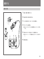
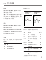
3-861-033-01 (2) CCD Color Video Camera Module J 取扱説明書 2 ペ−ジ Operating Instructions Page 46 お買い上げいただきありがとうございます。 警告 電気製品は、安全のための注意事項を守らないと、 火災や人身事故になることがあります。 この取扱説明書には、事故を防ぐための重要な注意事項と製品の取り扱いかたを示し てあります。この取扱説明書をよくお読みのうえ、製品を安全にお使いください。 お読みになったあとは、いつでも見られるところに必ず保管してください。 XC-333/333P 1997 by Sony Corporation EN 日本語 安全のために ソニー製品は安全に充分配慮して設計され ています。しかし、電気製品は、まちがった 使いかたをすると、火災や感電などにより 死亡や大けがなど人身事故につながること があり、危険です。 事故を防ぐために次のことを必ずお守りくだ さい。 安全のための注意事項を守る 4∼6 ページの注意事項をよくお読みくださ 故障したら使わない すぐに、お買い上げ店にご連絡ください。 万一、異常が起きたら 39 ページの「本機の性能を保持するために (使用上のご注意)」もあわせてお読みくだ さい。 この表示の注意事項を 警告 • 内部に水、異物が入ったら 守らないと、火災や感電などにより • 製品を落としたりキャビネットを 死亡や大けがなど人身事故につなが 破損したときは . 1 本機が接続されている専用接続機器の 電源を切る。 2 接続ケーブルを抜く。 3 お買い上げ店に連絡する。 く第一種情報技術装置です。この装置を 家庭環境で使用すると電波妨害を引き の内容や費用については、お買い上げ店 起こすことがあります。この場合には使 用者が適切な対策を講ずるよう要求され ることがあります。 2 ることがあります。 この表示の注意事項を 注意 守らないと、感電やその他の事故に よりけがをしたり周辺の物品に損害 を与えたりすることがあります。 注意を促す 記号 この装置は、情報処理装置等電波障害 期点検をすることをおすすめします。点検 にご相談ください。 内容をよく理解してから本文をお読 • 異常な音、においがしたら 自主規制協議会(VCCI)の基準に基づ 長期間、安全にお使いいただくために、定 のような表示をしています。表示の • 煙が出たら 注意 定期点検をする この取扱説明書および製品では、次 みください。 い。製品全般および設置の注意事項が記 されています。 警告表示の意味 行為を禁止 する記号 注意 火災 禁止 分解禁止 行為を指示 する記号 強制 目次 警告 ............................................................................... 4 メニューで行う調整と設定 ............................................. 22 注意 ............................................................................... 5 メニューの構成 .................................................................... 22 本機の特長 ........................................................................... 8 メニューの操作方法 ............................................................ 24 メニューの内容 .................................................................... 26 各部の名称と働き ............................................................... 9 カメラヘッドユニット................................................................ 9 カメラコントロールユニット (前面) ....................................... 10 カメラコントロールユニット (後面) ....................................... 12 メニューの初期設定一覧 .................................................... 35 カメラを2台以上使う ...................................................... 36 カメラを2 台以上使う場合の接続 ....................................... 36 カメラ間の画調を合わせる .................................................. 37 基本システムの接続と設置 ............................................. 14 コンポジット入力端子を持つ機器との接続 ........................ 15 コンピューターとの接続 ............................................... 38 接続の手順 .......................................................................... 16 本機の性能を保持するために(使用上のご注意)......... 39 レンズを取り付ける .............................................................. 17 CCD特有の現象 .............................................................. 40 三脚に取り付ける................................................................. 18 主な仕様 ............................................................................ 41 撮影する ............................................................................ 19 別売り専用アクセサリー ................................................ 43 撮影の手順 .......................................................................... 19 保証規定とアフターサービス ......................................... 44 ホワイ トバランスを自動調整する.......................................... 20 3 J 日 本 語 下記の注意を守らないと、 警告 火災 火災などにより死亡や大けがにつながることがあります。 内部に水や異物を入れない 水や異物が入ると、火災の原因となります。 禁止 万一、水や異物が入ったときは、すぐに本機が接続され ている電源供給機器の電源を切り、DC電源ケーブルや 接続ケーブルを抜いて、お買い上げ店にご相談くださ い。 分解や改造をしない 分解や改造をすると、火災やけがの原因となります。 分解禁止 内部の調整や設定、点検や修理は、お買い上げ店にご 依頼ください。 設置は確実に 設置については、必ずお買い上げ店にご相談ください。 強制 壁面や天井などへの設置は、本機および取り付け金具 を含む重量に充分耐えられる強度があることをお確かめ ください。充分な強度がないと、落下して、大けがの原 因となります。 また、1 年に1度は、取り付けがゆるんでないことを点検 してください。 4 下記の注意を守らないと、 注意 けがをしたり周辺の物品に損害を与えることがあります。 芯線の露出や断線などでDC電源ケーブルが傷んだら、 指定された電源を使う お買い上げ店に交換をご依頼ください。そのまま使用す この取扱説明書に記されている電源供給機器 (カメラア 強制 ると、火災の原因となります。 ダプターなど)でお使いください。規定外の電源でのご 使用は、火災の原因となることがあります。 指定されたDC電源ケーブル、接続ケー ブルを使う 強制 油煙、湯気、湿気、ほこりの多い場所 では設置・使用しない 禁止 上記のような場所に設置すると、火災の原因となること があります。 この取扱説明書に記されているDC電源ケーブル、接続 この取扱説明書に記されている仕様条件以外の環境で ケーブルを使わないと、火災や故障の原因となることが の使用は、火災の原因となることがあります。 あります。 不安定な場所に設置しない DC電源ケーブルを傷つけない DC電源ケーブルを傷つけると、火災や故障の原因とな 禁止 ることがあります。次の項目をお守りください。 • 設置時に、製品と壁やラック、棚などの間に、はさみ 込まない。 次のような場所に設置すると、倒れたり落ちたりして、け 強制 がの原因となることがあります。 • ぐらついた台の上 • 傾いたところ • 振動や衝撃のかかるところ • DC 電源ケーブルを加工したり、傷つけたりしない。 また、設置・取り付け場所の強度を充分にお確かめくだ • 重いものをのせたり、引っ張ったりしない。 さい。 • 熱器具に近づけたり、加熱したりしない。 • DC電源ケーブルを抜くときは、必ずプラグを持って抜 く。 5 下記の注意を守らないと、 注意 けがをしたり周辺の物品に損害を与えることがあります。 レンズの取り付けは確実に 専用レンズをご使用の場合、カメラヘッドとレンズをしっ 強制 かり締めて取り付けてください。また、専用レンズ以外の レンズをご使用の場合はカメラヘッド部分の破損、ゆる み等を防止するため、レンズ側で荷重を受けるように取 り付けてください。 取り付けかたがゆるいと、レンズがはずれて、けがの原 因となることがあります。 また、1 年に1 度は、取り付けがゆるんでいないことを点 検してください。 移動させるときは、DC電源ケーブル、 接続ケーブルを抜く 注意 接続したまま移動させると、DC電源ケーブルや接続ケー ブルが傷つき、火災の原因となることがあります。 また、ケーブルに引っかかって転倒するなど、けがの原 因となることがあります。 6 7 本機の特長 XC-333/333Pは 1/4インチの CCD (Charge-Coupled Device) を採 用したカメラヘッド分離型の超小型カラービデオカメラです。 DSP (Digital Signal Processor) を搭載したことによって、カラーマト カラーマトリクス調整 R、G、B、それぞれの色相を可変することができ、ホワイトバランスを くずすことなく好みの色再現が可能になります。 リクス調整等、豊富な機能を持ち、色再現のあざやかな画像を得る ことができます。 RS-232Cインターフェース装備 測光エリアと測光機能 RS-232Cインターフェースを装備していますので、コンピューターから 本機を制御できます。 AE、AGC、CCDアイリスの各モードに対し、5 種類の測光エリアの選 択とピーク/平均の切り換えが可能です。 また逆光補正機能により、逆光時も適正な光量で見やすい画像を得 られます。 広範囲な光量調整が可能 低照度撮影時に自動的に感度をアップするAGC(オートゲインコント ロール)機能に加え、過大な光量が入射したときシャッタースピード を調整するCCDアイリス機能を備えています。AGCとCCDアイリス を併用した AEコントロールにより、広範囲な入射光量に対応できま す。 8 各部の名称と働き カメラヘッドユニット 3M2ネジ穴 (深さ2.5 mm) 1レンズマウント(専用マウント) 別売りの専用レンズや Cマウントアダプター(LO-999CMT)などを取 り付けます。 2カメラ端子 別売りの専用ケーブルを接続します。 2カメラ端子 3M2ネジ穴(深さ2.5 mm) カメラヘッド設置時にご使用ください。寸法は下図を参照してくださ 3M2ネジ穴 (深さ2.5 mm) い。 1レンズマウント (専用マウント) M2ネジ穴寸法図(単位:mm) 底面 22 上面 5 (2個) M2ネジ穴(深さ2.5 mm) 12 12 5 (4個) M2ネジ穴(深さ2.5 mm) 9 各部の名称と働き カメラコントロールユニット(前面) 1POWER(電源)スイッチ 1POWERスイッチ このスイッチを押すと、カメラコントロールユニット、カメラヘッドユニッ トなどに電源が供給されます。 2MENUボタン 2MENU(メニュー)ボタン 3選択ボタン(◊/√/ı/∫ボタン) 4AUTO WHITEボタン 押すと、条件設定用のメニューがモニター画面に表示されます。もう 1 度押すと、メニューが消えます。 ◆ メニュー操作については「メニューで行う調整と設定」の「メニューの 操作方法」 (24 ページ)をご覧ください。 3選択ボタン(◊/√/ı/∫ボタン) ◊ボタン:押すと、メニュー表示の点滅する位置が上に動きます。 √ボタン:押すと、メニュー表示の点滅する位置が下に動きます。 ıボタン:押すと、メニュー表示の点滅する位置が左に動くか、数値 が下がります。またメニューページを切り換えます。 6DISPボタン 5CAMERA端子 10 ∫ボタン:押すと、メニュー表示の点滅する位置が右に動くか、数値 が上がります。またメニューページを切り換えます。 4AUTO WHITE(オートホワイトバランス)ボタン 6DISPボタン メニューが表示されていない場合に、このスイッチを約 1 秒間押しつ メニューが表示されていないときに、記憶されている2 種類(A、B) づけると、ホワイ トバランスが自動的に調整されます。 の設定を選ぶのに押します。ボタンを押すごとに A n B n LIVEn PAGE 2メニューが表示されていて、 「W. B.」が「AWB」に設定さ A n B n LIVEn....と切り換わります。このとき、画面右上に「A」 れ、 「AWB」が点滅している場合、このボタンを押すと同じように機 または「B」の文字を表示します (LIVE の場合は何も表示しない) 。 能します。 メニュー表示中に押すと、選ばれている項目が 1 項目表示となり、 ◆ 詳しくは、 「メニューで行う調整と設定」の「PAGE 2メニュー」 (29ペー ジ)をご覧ください。 ご注意 画面上部に表示されます。 (メニュー表示中、ページが選ばれているときは、ボタンを押すごと に A n B n LIVE...と切り換わります。) 画面が記憶されているA、あるいは B の設定になっている場合で、メ ニューが表示されていない場合でも、AUTO WHITEボタンを押すと設定 は「AWB」に切り換わりますが、PAGE 5メニューの「SAVE」で設定値 を保存しない限り、記憶はされません。 5CAMERA(カメラ)端子 カメラヘッドに接続したケーブルの反対側をここにつなぎます。 11 各部の名称と働き カメラコントロールユニット(後面) 1GEN LOCK (ゲンロック入力)端子(BNC型) 1GEN LOCK端子 複数のカメラを同期させるときに、基準となる外部同期信号を入力し ます。VBS で同期がかかります。 2Y/C端子 3VIDEO OUT端子 4DC IN/VBS端子 2Y/C端子(S端子) カメラの映像をY(輝度)信号とC(色)信号に分離して出力しま す。DIN4ピンコネクター付きケーブル(別売り)で、モニターや VTR のY/C 入力端子に接続できます。 3VIDEO OUT(映像出力)端子(BNC型) カメラからの映像をコンポジット信号として出力します。 4DC IN(直流電源入力)/VBS(映像出力)端子(12ピン) カメラアダプターDC-777/777CE(別売り)などを接続します。 6RS-232C端子 5WE OUT端子 12 カメラアダプターから本機に電源が供給され、本機からビデオ信号を 出力します。 5WE OUT出力端子 長時間露光(蓄積)のタイミングに合わせ、信号が出力されます(タ イミングパルス出力) 。ビデオキャプチャーボード等への画像の記録 にご利用ください。 ◆ 詳しくは「メニューで行う調整と設定」の「PAGE 1メニュー」 (26 ペー ジ)をご覧ください。 6RS-232C端子(8ピン) パーソナルコンピューターを接続します。RS-232Cシリアルインター フェイスにより各種機能のコントロールが可能です。 (詳しくは、お買 い上げ店までお問い合わせください。) 13 基本システムの接続と設置 本機へ電源を供給するには、カメラアダプターDC-777/777CE(別 接続するときのご注意 売り)などを使用します。 • 接続するすべての機器の電源を切ってください。特に、電源を入れ CCXCケーブルを使用してください。 • 接続ケーブルは、 それぞれの端子の形状に合った正しいものを選ん たままカメラケーブルを着脱すると、本機が破損する場合があります。 電源を供給し、VBS、Y/C 信号を出力します。 ◆ 接続図については、 「コンポジット入力端子を持つ機器との接続」 (15 ページ)をご覧ください。 でください。 • プラグはしっかり差し込んでください。不完全な接続は雑音、ノイズ の原因になります。 また抜くときは、必ずプラグを持って抜いてくださ い。 • カメラヘッドとカメラコントロールユニットは、 シリアルNo.が同じになっ ています。良質な画像を保持するため異なったシリアルでのご使用 はご遠慮ください。 14 コンポジット入力端子を持つ機器との接続 ビデオモニター、VTRなど カメラヘッドユニット 75Ω同軸ケーブル コンポジットビデオ入力端子 (VIDEO IN) レンズ カメラケーブル VIDEO OUT クランプ フィルター (付属) カメラアダプターDC-777/777CE カメラコントロール ユニット 電源コード CAMERA (前面) a) DC IN/VBS VBS出力 Y/C出力a) CCXC-12P02S/05S/10S/25Sケーブル CAMERA a) DC-777/777CE のVBS 出力、および Y/C 出力は 同時には使用できません。 CCXCケーブルを使って接続するシステム 15 基本システムの接続と設置 接続の手順 1 カメラケーブルをカメラコントロールユニットにつなぐ。 溝 ご注意 • レンズを取り扱うときはゴミや指紋がレンズ表面につかないように ご注意ください。 • カメラケーブルのプラグはどちらをカメラコントロールユニット側に つないでもかまいません。 クランプフィルターの取り付けかた ヨーロッパにてご使用の際は付属のクランプフィルターを取り付けてく 上の溝に合わせて深く差し込んでからネジを締める。 2 カメラヘッドをケーブルに取り付ける。 ださい。クランプフィルターは閉じていますので、マイナスドライバー などで開いてから下図のように取り付けてください。 溝を合わせる 3 カメラヘッドに専用レンズをゆっくり回しながら取り付ける。 4 カメラアダプターDC-777/777CEなどとモニターを接続する。 5 電源コードを接続する。 接続が終わったら: まずモニターの電源を入れ、最後にカメラコントロールユニットの電 源を入れてください。 16 カメラコントロールユニッ ト側に取り付けます。 レンズを取り付ける 専用レンズ(別売り) Cマウント式レンズ(別売り) 1 レンズマウントキャップを回して外す。 1 2 レンズを回して取り付ける。 レンズマウント 1 キャップを回して外す。 2 1 Cマウントアダプターを 回して取り付ける 3 取り付ける。 2 2 レンズを回して 3 Cマウントレンズを取り付ける場合はCマウントアダプターLO-999CMT (別売り)が必要です。C マウントレンズはレンズマウント面からの飛び 使用できるレンズは次の通りです。 出し量が 4.1mm 以下のものを使用してください。 スペシャル (NF) マウントレンズ(別売り) ・ VCL-12S12XM(f=12 mm) レンズマウント面 4.1mm以下 ・ VCL-06S12XM(f=6 mm) ・ VCL-03S12XM(f=3.5 mm) ・ VCL-12SXM(f=12 mm) ご注意 VCL-7S12XEA(オートアイリスレンズ)は、取り付けることができませ ん。 ご注意 ・ Cマウントアダプターをご使用時のカメラ設置については、 カメラヘッ ドを固定せず、C マウントレンズを固定して、無理な力がカメラヘッド にかからないようにご注意ください。 ・ 振動や衝撃の多いところでのCマウントアダプターご使用は破損、ゆ るみなどの原因になります。 17 基本システムの接続と設置 三脚に取り付ける 三脚に取り付けるときは、三脚アダプターVCT-333I(別売り)をご使 用ください。また三脚取り付け部のネジは、4∼5mm のものをご使用 ください。 4∼5mm 三脚アダプター(VCT-333I)を 付属のネジで取り付ける 18 撮影する 撮影の手順 2 1 接続した機器の電源を入れる。 2 適度な照明光で被写体を照明する。 3 レンズを被写体に向け、絞り・ピントなどを調整する。 4 ホワイトバランスを調整する。 ◆ 詳しくは、 「ホワイ トバランスを自動調整する」 (23ページ)をご覧く ださい。 3 1 5 5 必要ならばシステムや用途に応じて、機能設定をする。 ◆ 詳しくは、 「メニューで行う調整と設定」 (22 ページ)をご覧くださ い。 4 6 撮影を開始する。 19 撮影する ホワイトバランスを自動調整する 照明条件が変わったときは、自然な色調の画像を得るために、必ず 操作手順 ホワイトバランスを調整してください。 1 被写体と同じ照明条件のところに、白いもの(白紙や白布)を 置き、画面全体に白を映す。ただし、極端な高輝度部分が入ら ないようにしてください。 被写体の近くの白い物(白壁など)でも代用できます。 ご注意 • 高輝度の被写体を画面に入れないでください。 • 適度な明るさの照明下で撮影してください。 2 AUTO WHITE カメラコントロールユニットの前面パネルにあるAUTO WHITE ボタンを1 秒以上押す。 (メニューが表示されていない場合) 調整が終了すると、モニター画面に「OK」と 表示されます。 調整値は、電源を切っても記憶されます。次回も同じ条件で撮影 するときは、PAGE 2メニューの「W. B.」で「AWB」を選ぶと、記憶 されているホワイ トバランスが再現されます。 ご注意 画面が記憶されているA、あるいは B の設定になっている場合で、メ ニューが表示されていない場合でも、AUTO WHITEボタンを押すと設定 は「AWB」に切り換わりますが、PAGE 5メニューの「SAVE」で設定値 を保存しない限り、記憶はされません。 20 調整できなかったときは ホワイ トバランスが自動調整できなかったときは、 「NG」がモニター 画面に表示されます。絞りを調整するか周辺の明るさを調整してから もう一度操作手順を行ってください。 21 メニューで行う調整と設定 本機では、撮影や出力などの設定値をモニター画面に表示されるメ ニューを見ながら、ボタン操作で変更することができます。 より良質な画像や目的に合う画像効果を得ることができ、カメラの利 用範囲が広がります。 PAGE 1メニュー PAGE 2メニュー PAGE1 PAGE 2 AE MODE AUTO OFF AREA BL FUL C1 C2 S 1 S2 PEAK AVE AE L EVE L + 1 F L I CKER AUTO OF F W. E. A TW AWB 5 6 0 0 3 2 0 0 PUSH R+ 0 B+ 0 PEDES T AL + 1 GAMMA + 3 H ENH – 2 V ENH – 1 ZOOM ON OF F X 1.4 5 メニューの構成 メニューは全部で 5 ページあります。 PAGE 5 PAGE 3 メニュー メニュー PAGE5 MEMORY SAVE RESET PAGE3 YES YES BAR F U L L H I LOW OFF MEGA ON OFF OUT PU T VBS Y / C BAUD RA T E 4 80 0 9 600 1 9 200 NO NO メニューを表示するには カメラコントロールユニットの前面パネルにあるMENUボタンを押しま す。 PAGE 4メニュー PAGE4 COLOR MAT R I X R G B COLOR ON OFF ON OFF +1 0 – 6 + 0 メニューページが点滅しているときは、選択ボタ ン (ıまたは∫ボタン) を押すごとにメニューペー ジが切り換わる。 22 3設定値 メニュー画面の読みかた 実際の操作を始める前にメニュー画面の読みかたを説明します。 現在選択されている設定値を表示します。 選択ボタン (ıまたは ∫ボタン) で変更します。 1 PAGE1 2 AE MODE AUTO OFF AREA BL FUL C1 C2 S 1 S2 PEAK AVE F L I CKER AUTO OFF SHU T TER AUTO MANUAL OFF 5 1 2 F LD ODD E VEN GA I N AGC MANUA L 12dB A 3 1メニューページ 選択されているメニューページを表示します。 メニューページを変えるには、メニューページが緑色で点滅している ときに、選択ボタン (ıまたは ∫ボタン) を押します。 2設定項目 各ページで設定できる項目が表示されます。 選択ボタン (◊または √ボタン) で変更します。 23 メニューで行う調整と設定 メニューの操作方法 下表にボタンの働きを示します。 メニュー操作ボタン メニューはカメラコントロールユニットにあるメニュー操作ボタンを使っ ボタン 働き て操作します。 MENU 押すとメニューが表示される。 もう一度押すとメニューが消える。 ◊ 点滅する位置を上げる。 √ 点滅する位置を下げる。 ı 点滅する位置を左に動かす。メニューページを切り換える。 調整・設定値を下げる。 ∫ 点滅する位置を右に動かす。メニューページを切り換える。 調整・設定値を上げる。 DISP メニューページが点滅しているときとメニューが出ていない とき:A、Bを表示する。 設定項目が選択されているとき:1 項目を表示する。 ıボタン MENU ◊ボタン ∫ボタン ボタン √ボタン DISP ボタン 24 3 操作手順 点滅させる。 メニューで設定を変更するには、次のように操作します。 1 選択ボタン (◊または√ボタン) を押して、変更したい設定項目を PAGE 2 MENUボタンを押す。 設定項目 前回選択したメニューページが表示されます。 W. B. PEDES T AL GAMMA H ENH V ENH ZOOM PAGE1 AE MODE AUTO OFF AREA BL FUL C1 C2 S 1 S2 PEAK AVE AE L EVE L + 1 F L I CKER AUTO OF F 4 2 A TW AWB 5 6 0 0 3 2 0 0 設定したい項目のあるメニューページを選ぶ。 メニューページが点滅している状態で選択ボタン(ıまたは∫ボタ ン) を押して、メニューページを選ぶ。 PAGE1 PAGE 2 AE MODE AUTO OFF AREA BL FUL C1 C2 S 1 S2 PEAK AVE AE L EVE L + 1 F L I CKER AUTO OF F W. B. A TW AWB 5 6 0 0 3 2 0 0 0 PUSH R+ B+ 0 PEDES T AL + 1 GAMMA + 3 H ENH – 2 V ENH – 1 ZOOM ON OF F X 1.4 5 + 1 + 3 – 2 – 1 ON OF F X 1.4 5 選択ボタン (ıまたは ∫ボタン) を押して、設定値を変更する。 PAGE 2 W. B. A TW AWB 5 6 0 0 3 2 0 0 PEDES T AL GAMMA H ENH V ENH ZOOM + 1 + 3 2 – – 1 ON OF F X 1.4 5 設定値 通常画面に戻るには MENUボタンを押します。LIVE の画面でこのとき設定した値は MENUボタンを押してメニューを閉じることにより記憶されます(次 回電源を入れるとき、その設定になっている) 。 25 メニューの内容 AE MODE PAGE 1メニュー 自動露光の設定をオン/オフします。 AE MODEでAUTOを選ぶと AE MODEでOFFを選ぶと PAGE1 PAGE1 AE MODE AUTO OFF AREA BL FUL C1 C2 S 1 S2 PEAK AVE AE L EVE L + 1 F L I CKER AUTO OF F AE MODE AUTO OFF AREA BL FUL C1 C2 S 1 S2 PEAK AVE F L I CKER AUTO OFF SHU T TER AUTO MANUAL OFF 5 1 2 F LD ODD E VEN GA I N AGC MANUA L 12dB 機能 露光を自動調整します。 (SHUTTER のAUTOとGAIN AGCが連続的に動作します。) SHUTTERとGAIN の項目が消えて、標準値を0として、 − 60∼+ 60 の間で AE LEVELが設定できます。 ご注意 被写体が明るすぎたり、暗すぎると、 「AUTO」を選択した とき、AE LEVELを正しく設定することができない場合があ ります。 PAGE 1メニューで設定できる項目について説明します。 OFF 項目 設定内容 AE MODE 自動露光のオン/オフ。 26 AREA 測光枠の設定。 27 FLICKER 蛍光灯等のフリッカーをキャンセルする機能。 27 SHUTTER 電子シャッターの各種設定。 27 GAIN ゲイン(映像利得)の調整。 29 26 設定項目 AUTO 参照ページ SHUTTERとGAIN の項目を希望する値に設定できます。 メニューで行う調整と設定 AREA DISPスイッチを押して 1 項目表示にすると、測光枠が画面に表示さ 撮影条件により、測光枠を選ぶことができます。 れます。 • 測光枠は、逆光補正(BL) 、全画面(FUL) 、センター1(C1) 、セン ター2(C2) 、スリット1(S1) 、スリット2(S2) の中から選択できます。 FLICKER 逆光補正は、順光の被写体以外に、逆光の被写体も適正な露光に 蛍光灯下で撮影するとき、映像のちらつきをなくして撮影することが なるよう動作します。 できます。 設定項目 AUTO 機能 ちらつきを消します。シャッタースピードが 1/60 (XC-333) または 1/50 (XC-333P)∼1/200 程度の範囲で機能します。 ご注意 全画面(FUL) センター1(C1) • 測光方式が「PEAK」に選択されていると、フリッカー キャンセル機能は働きません。 センター2(C2) • 複数の蛍光灯の下では効果が薄れることがあります。 OFF スリット1(S1) スリット2(S2) 測光枠 • FUL、C1、C2、S1、S2を選択した場合は、更にピーク測光(PEAK) と平均測光(AVE)を選択できます。 ピーク測光(PEAK):測光枠中の画像の最大輝度を基準に露光を 決めます。 平均測光(AVE): 通常はこの位置にしておきます。 SHUTTER 電子シャッターのスピードを設定します。AE MODEが OFF の場合に 設定できます。 動きの早い被写体を、ブレを少なくして撮影したいときや暗い被写 体を明るい静止画として撮影したいときは、この電子シャッター機能 を使用すると便利です。 測光枠中の画像の平均輝度を基準に露光を 決めます。 27 設定項目 機能 AUTO 被写体の明るさが過大なとき、映像レベルが最適になる ように電子シャッターが働き、光量を自動的に調整します。 標準値を0として、−60∼+ 60 の間で AE LEVELが設 定できます。 で設定できます。 蓄積範囲:2∼512フィールド 長時間蓄積モードでシャッタースピードを設定するには選 ı または ∫ボタン) で希望の設定値を表示しま 択ボタン (ı す。ボタンを押すごとに、2∼512フィールドまで 1フィール ドずつシャッタースピードが変わります。ボタンを押し続け ると切り替わるスピードが速くなります。ı ボタンと∫ボタン を同時に押すと、1/60 (XC-333) または 1/50 (XC-333P) に戻ります。フィールド数が偶数の場合、ODD(奇数)と EVEN(偶数)が選べます。 ご注意 「AUTO」に設定したときは、 「GAIN」を0dBにしてくださ い。 MANUAL シャッタースピードを1/60 (XC-333) または 1/50 (XC333P)、1/100、1/125、1/250、1/500、1/1000、1/2000、1/ 4000、1/8000、1/10000、1/20000、1/40000 の12 段階に 変えられます。 ı または ∫ シャッタースピードを設定するには選択ボタン (ı ボタン) を押します。ボタンを押し続けると切り替わるス ピードが速くなります。ı ボタンと∫ボタンを同時に押すと、 1/60 (XC-333) または 1/50 (XC-333P) に戻ります。 長時間蓄積モードではシャッタースピードをフィールド単位 ご注意 蓄積時間が増す程、CCD のもっているノイズも蓄積される ので、画面に出るノイズも大きくなります。 WE (タイミングパルス)a) 信号をカメラコントロールユニッ トの裏面の WE OUT 端子から出力します。 OFF a) 電子シャッターは働きません。 長時間蓄積モードで映像信号を出力するためのタイミングパルスです。 電子シャッターの長時間蓄積モード時におけるタイミングチャート Highレベル 4.5∼5.0V WEパルス Lowレベル 0∼0.5V パルス幅 1.5∼7 msec 映像信号 0.5∼5 msec 28 メニューで行う調整と設定 GAIN PAGE 2メニュー ゲイン(映像利得)を調整します。 設定項目 機能 AGC ゲインを自動調整します。 (オートゲインコントロール) 被写体の明るさに応じて、ゲインが自動調整されます。被 写体の照度が暗い場合の明るさの自動調整に適していま す。標準値を0として、−60∼+ 60 の間で AE LEVELが 設定できます。 PAGE 2 W. B. A TW AWB 5 6 0 0 3 2 0 0 0 PUSH R+ B+ 0 PEDES T AL + 1 GAMMA + 3 2 H ENH – V ENH – 1 ZOOM ON OF F X 1.4 5 MANUAL ゲインを希望する値に設定できます。0∼12 dBまで 1 dB 刻 みで設定できます。ゲインを設定するには選択ボタン(ı ıま たは ∫ ボタン)を押します。ボタンを押し続けると切り換わ るスピードが速くなり、両ボタンを同時に押すと0に戻りま す。 暗い場所で撮影する場合など、絞りを開放にしても画像が 暗いときに使います。 PAGE 2メニューで設定できる項目は次のとおりです。 項目 設定内容 参照ページ W.B. ホワイトバランスの設定。 30 PEDESTAL ペデスタルレベルの設定。 30 GAMMA ガンマ補正の設定。 30 H ENH 水平エンハンスの設定。 31 V ENH 垂直エンハンスの設定。 31 ZOOM ズームの設定。 31 29 W. B. PEDESTAL ホワイトバランスの設定を選びます。 通常は 0 の設定にしておきます。 設定項目 機能 画像の黒い部分がつぶれている場合など、必要により黒い部分の ATW オートトレーシングホワイトバランスが作動します。 この設定は光源が変化する撮影に適しています。色温度 の推移にともなってホワイ トバランスが自動調整されます。 この設定にしておくと、ホワイ トバランスの自動調整ができ ます。 (オートホワイ トバランス) ◆「ホワイトバランスを自動調整する」 (20 ページ)を参考 にしてください。 この項目を選ぶと、 「R」と「B」がメニュー上に表示されま す。ホワイトバランスの微調整を更に行いたいときに使いま す。それぞれモニター画面を見ながら調整してください。 R : 赤のゲインを調整します。−128∼+ 127まで設定でき ます。 B : 青のゲインを調整します。−128∼+ 127まで設定でき ます。 選択ボタン (ı ı ボタンと∫ボタン) を同時に押すと、0に戻り ます。 屋外で撮影するときに適しています。 「R」と「B」がメ ニュー上に表示されます。設定の方法は「AWB」の場合 と同じです。 室内で撮影するときに適しています。 「R」と「B」がメ ニュー上に表示されます。設定の方法は「AWB」の場合 と同じです。 再現性を調整できます。頭髪など画面内の黒い部分の細部がはっき AWB 5600 3200 30 り見えるように調整してください。波形モニターを使うと調整が容易に なります。 出力信号のペデスタルレベルを− 10∼+ 40 の範囲で設定できす。 ı または ∫ボタン) で希望の設定値を表示 設定するには選択ボタン (ı させます。ı ボタンと∫ボタンを同時に押すと、0に戻ります。 GAMMA ガンマを補正します。 通常は 0 の設定にしておきます。モニターのブラウン管の受像特性を 補正した自然な階調が得られます。 ガンマレベルを− 16∼+ 15 の範囲で設定できます。設定するには ı または ∫ボタン) で希望の設定値を表示させます。ı 選択ボタン (ı ボタンと∫ボタンを同時に押すと、0に戻ります。 ハイライ ト部分の階調のコントラストを強め、見やすくしたい場合は、 −方向にします。この場合、暗い部分のコントラストは弱まります。逆 に暗い部分の階調のコントラストを強めたい場合は+方向にします。 この場合、ハイライト部分のコントラストは弱まります。 メニューで行う調整と設定 H ENH PAGE 3メニュー 画面の水平方向に輪郭を強調します。 (縦の線がはっきりします。) 外部同期信号が入力さ れていない場合 通常は 0 の設定にしておきます。 外部同期信号が入力さ れている場合 必要により− 16∼+ 15 の範囲で設定できます。設定するには選択 ı または ∫ボタン) で希望の設定値を表示させます。ı ボタン ボタン (ı PAGE3 PAGE3 と∫ボタンを同時に押すと、0に戻ります。 BAR F UL L H I L OW OFF NEGA ON OF F OUTP UT VBS Y / C BAUD R AT E 4 800 9 600 1 9 200 BAR F U L L H I LOW OFF NEGA ON OFF OUT PU T VBS Y / C BAUD RA T E 4 80 0 9 600 1 9 200 SC PH ASE 3 SC O / 1 8 0 0 180 H PHASE 6 V ENH 画面の垂直方向に輪郭を強調します。 (横の線がはっきりします。) 通常は 0 の設定にしておきます。 必要により− 16∼+ 15 の範囲で設定できます。設定するには選択 ı または ∫ボタン) で希望の設定値を表示させます。ı ボタン ボタン (ı と∫ボタンを同時に押すと、0に戻ります。 ZOOM PAGE 3メニューで設定できる項目は次のとおりです。 項目 設定内容 BAR カラーバーの画面表示位置。 32 NEGA 画面のネガ/ポジ表示の切り換え。 32 OUTPUT 12ピンコネクターの映像出力信号の 選択。 32 ボーレートの設定。 32 SC PHASE 外部同期時のSC(サブキャリア)の 位相差の調整。 32 SC 0/180a) SC(サブキャリア)の位相の反転角度の 選択。 32 H.PHASEa) 外部同期時のH(水平)同期の位相差の 調整。 32 電子ズームのオン/オフをします。ズームオン時には約 1∼3 倍まで 設定できます。 設定項目 機能 ON 電子ズームを起動します。 OFF 電子ズームを起動しません。 BAUD RATE a) a) 外部同期信号が入力されたときにのみ表示されます。 参照ページ 31 BAR BAUD RATE カラーバーを画面のどの位置に表示するか選びます。 RS-232Cインターフェイスのボーレート(19200/9600/4800)を切り換 えます。 設定項目 機能 FULL カラーバーを画面一杯に表示します。 HI カラーバーを画面の下側に大きく表示します。 SC PHASE LOW カラーバーを画面の下側に小さく表示します。 本機にゲンロック(Generator Lock、外部同期)をかけたときのSC OFF カラーバーを画面に表示しません。 (サブキャリア)位相を合わせるときに使います。0/180 で大まかに調 ıま 整し、0∼255 の範囲で微調整します。設定するには選択ボタン(ı NEGA たは ∫ボタン)で希望の設定値を表示させます。ı ボタンと∫ボタン 普通の画面をネガ画面に切り換えます。写真のネガフィルムなどを撮 を同時に押すと、0に戻ります。 影するときに使います。 設定項目 機能 SC 0/180 ON 画面をネガ表示にします。 本機にゲンロック(外部同期)をかけたときの SC(サブキャリア)位 OFF 画面をネガ表示にしません。 相を大まかに調整をします。 OUTPUT H.PHASE カメラアダプターDC-777/777CE(別売り)を使った場合、カメラコン 本機にゲンロック(外部同期)をかけ、H 位相を合わせるときに使い トロールユニットの裏面にある12ピンコネクターの映像出力信号を選 ます。 択します。 ı または 0∼255 の範囲で調整できます。設定するには選択ボタン(ı 設定項目 機能 ∫ボタン)で希望の設定値を表示させます。ı ボタンと∫ボタンを同 VBS VBS 出力信号を選びます。 時に押すと、0に戻ります。 Y/C Y/C 出力信号を選びます。 32 メニューで行う調整と設定 COLOR MATRIX PAGE 4メニュー 設定項目 ON PAGE4 COLOR MAT R I X R G B COLOR ON OFF ON OFF +1 0 – 6 + 0 機能 画面の色相の調整をします。 「R(赤っぽい色) 」 、 「G (緑っぽい色)」 、 「B(青っぽい色)」を別個に調整でき ます。0を標準値として、− 60∼+ 60 の範囲で設定でき ます。設定するには選択ボタン (ı ı または ∫ボタン) で希 望の設定値を表示させます。ı ボタンと∫ボタンを同時 に押すと、0に戻ります。 ご注意 AE MODE の設定が AUTO の場合、あるいは W.B. の 設定が ATW の場合 , 多少他の色へも影響する場合があ ります。 PAGE 4メニューで設定できる項目は次のとおりです。 項目 設定内容 参照ページ COLOR MATRIX 画面の色相の調整。 33 COLOR カラー画面か白黒画面かの選択。 33 OFF 画面の色相を標準状態に戻します。 COLOR 設定項目 機能 ON カラー画面になります。 OFF 白黒画面になります。 33 ご注意 PAGE 5メニュー • LIVE の状態で SAVEを選ぶとLIVE の設定が保存されます。 (メ ニューを閉じたとき、保存される動作と同じです。) PAGE5 MEMORY SAVE RESET •「A」 、または「B」で設定を変更し、PAGE 5を出さずにMENUスイッ YES YES NO NO チによりメニューを閉じようとしたとき、保存忘れを防止するため、一 度、PAGE 5メニューが表示されます。 RESET 各メニューで調整、設定した値を工場出荷時の設定に戻すかもどさ ないかを選択します。 PAGE 5メニューで設定できる項目は次のとおりです。 項目 設定内容 参照ページ SAVE ユーザー設定値の保存。 34 RESET 工場出荷時の設定に戻る。 34 SAVE A、B 2 つのユーザー設定を保存する/しないの切り換えを行いま す。 ユーザー設定を保存するには 1 DISPを押して登録したいユーザー設定「A」 、または「B」を選ぶ。 2 メニューPAGE 1∼PAGE 4 上で、必要な調整/設定を行う。 3 「SAVE」で「YES」を選ぶ。 34 設定項目 YES 設定内容 工場出荷時の設定に戻す。 (すべての設定が工場出荷時 に戻されます。) NO 工場出荷時の設定に戻さない。 メニューで行う調整と設定 メニューの初期設定一覧 メニューページ 設定項目 初期設定値 メニューページ 設定項目 PAGE 1 AE MODE AUTO PAGE 3 AREA FUL AVE AE LEVEL FLICKER OFF SHUTTERa) OFF 1/60 (XC-333) または 1/50 (XC333P) GAINa) PAGE 2 +0 MANUAL 0 dB W. B. Rb) Bb) ATW 0 0 PEDESTAL +0 GAMMA +0 H ENH +0 V ENH +0 ZOOM OFF ×1.00c) OFF NEGA OFF OUTPUT VBS BAUD RATE 19200 SC PHASEd) 0 SC 0/180 PAGE 4 PAGE 5 初期設定値 BAR d) 0 H PHASEd) 0 COLOR MATRIX Re) Ge) Be) OFF 0 0 0 COLOR ON SAVE NO RESET NO a) 「AE MODE」が「MANUAL」に設定されている内容 「W. B.」の設定が「AWB」 、 「5600」 、 「3200」のときに設定されている 内容 c) 「ZOOM」の設定が「ON」のときに設定されている内容 d) 外部同期信号が入力しているときに設定されている内容 e) 「COLOR MATRIX」が「ON」のときに設定されている内容 b) 35 カメラを2台以上使う カメラを2台以上使う場合の接続 カメラを2台以上使うときのご注意 スイッチャーなどを使って、数台のカメラの画像を切り換えてモニター するときは、カメラ間の画調合わせのために、次のことを行ってくださ • SC(サブキャリア)位相とH(水平)位相を調整する。 ◆ 詳しくは「カメラ間の画調を合わせる」 (次ページ)をご覧ください。 い。 同期信号発生器または カメラ DC IN/VBS カメラコントロール ユニット GEN LOCK 同期信号出力端子 (VBS) CAMERA 75Ω同軸ケーブル VBS OUT CCXC-12P02S/05S/10S/25Sケーブル DC IN/VBS 75Ω同軸ケーブル 36 カメラアダプターDC-777/777CE VBS OUT GEN LOCK ビデオモニター、 VTRなど 電源コード カメラコントロール ユニット VBS IN スイッチャーなど VBS IN カメラアダプターDC-777/777CE VIDEO OUT CAMERA CCXC-12P02S/05S/10S/25S-ケーブル 電源コード カメラ間の画調を合わせる カメラを数台使うときは、各カメラで撮影した画像の色調が同じになる ように、各カメラ間の画調を合わせてください。 すべてのカメラに同じ同期信号を供給しておきます。 ◆ 接続については、 「カメラを2台以上使う場合の接続」 (前ページ)をご 覧ください。 位相チェック表示機能を持たない機器を使う場合 基準にするカメラを決めて、そのカメラの画調に、他のカメラの画調を 合わせます。 1 PAGE 3メニューの「H.PHASE」で「H」 (水平)位相を調整する。 位相チェック表示機能を持つ機器が使える場合 「H. PHASE」で、基準信号の水平同期信号と、出力信号の水平 位相チェック表示機能を持つ特殊効果装置やクロマキーヤーなどにカ 同期信号の位相が同じになるように調整します。波形モニターや メラを接続している場合は、以下のように調整します。 オシロスコープを使って調整してください。 1 特殊効果装置かクロマキーヤーの PHASE INDICATIONスイッ チをONにする。 2 3 2 PAGE 3メニューの「SC PHASE」で SC 位相を調整する。 PAGE 3メニューの「H.PHASE」で H(水平)位相を調整する。 「SC 0/180」で、0° または180° の調整を行います。ベクトルスコー ◆詳しくは、 「メニューで行う調整と設定」の「PAGE 3メニュー」 (31 ページ)をご覧ください。 プを使うか、 または特殊効果装置のワイプ機能で、2台のカメラの 画像を上下または左右に半分ずつ映して、調整してください。 PAGE 3メニューの「SC PHASE」で SC(サブキャリア)位相を 調整する。 「SC 0/180」で 0° または 180° の調整を行ってください。 ◆詳しくは、特殊効果装置やクロマキーヤーの説明書をご覧ください。 37 コンピューターとの接続 コンピューターのRS-232Cインターフェイスで本機をコントロールするシ ステムを下図に示します。 75Ω同軸ケーブル カメラヘッドユニット ビデオモニター、 VTRなど 映像入力端子 レンズ カメラケーブル カメラコント ロールユニット VIDEO OUT DC IN/VBS CAMERA (前面) RC-232C 接続ケーブルa) カメラアダプターDC-777/777CE VBS 出力 接続ケーブルa) b) 電源コード CAMERA Y/C出力b) CCXC-12P02S/05S/10S/25Sケーブル コンピューター シリアルインター フェース端子 38 a) 本機とコンピューターの接続には、特定のシールド タイプの接続ケーブルを使用してください。 b) DC-777/777CE のVBS 出力、および Y/C 出力 は同時には使用できません。 ◆ 本機とコンピューターを接続する接続ケーブル、 RS-232C 通信仕様については、お買い上げ店ま でお問い合わせください。 本機の性能を保持するために(使用上のご注意) 使用・保管場所 輸送 次のような場所での使用および保管は避けてください。 輸送するときは、付属のカートンとクッション、または同等品で梱包し、 • 極端に暑い所や寒い所(動作温度は 0℃∼40℃) 強い衝撃を与えないようにしてください。 • 直射日光が長時間あたる場所や暖房器具の近く • 強い磁気を発するものの近く • 強力な電波を発するテレビやラジオの送信所の近く お手入れ • レンズや光学フィルターの表面に付着したごみやほこりは、ブロアー で払ってください。 放熱 • 外装の汚れは、乾いたやわらかい布で軽く拭き取ってください。汚れ 動作中は布などで包まないでください。内部の温度が上がり、故障や がひどいときは、中性洗剤溶液を少し含ませた布で汚れを拭き取っ 事故の原因となります。 た後、からぶきしてください。 • アルコール、ベンジン、シンナー、殺虫剤など揮発性のものをかける と、表面の仕上げをいためたり、表示が消えたりすることがあります。 39 CCD特有の現象 CCDカメラの場合、次のような現象が起きることがありますが、故障で はありません。 折り返しひずみ 縞模様、線などを写したとき、ギザギザのちらつきが見えることがありま す。 スミア 高輝度の被写体を写したときに、明るい帯状の縦線(垂直スミア) がモ ニター画面に見える現象です。 (下図参照) 傷 CCDはフォトセンサー(素子)が縦横に並んでできており、フォトセン サーのいずれかに欠陥があると、その部分だけ画像が写らず、モニ ター画面に傷となって見えます(実用上支障がない程度) 。 縦に薄く尾を引いたよ うな画像になる。 (垂直スミア) 微小白点 モニター 画面 高温時に暗い被写体を写している場合、画面全体に多数の白点が現 高輝度の被写体 (電灯、蛍光灯、太 陽、強い反射光など) この現象は、CCDがインターライン転送方式を採用しているため、フォ トセンサーの深いところに入った赤外線などにより誘起された電荷が、 レジスターに転送されるために起こるものです。 40 れることがあります。 主な仕様 撮像部・光学系 撮像素子 有効画素数 感度 インターライン型 1/4インチ CCD スペシャル (NF) マウント XC-333 : 46 dB 以上 XC-333P : 44 dB 以上 XC-333 : 768 (H) ×494 (V) XC-333P : 752 (H) ×582 (V) レンズマウント SN 比 2000 lx(F5.6、3200K) ゲイン切り換え AGC、および 0∼12 dB(1 dBステップ) ホワイ トバランス ATW、AWB(R、B 微調整可能) 、5600 (R、B 微調整可能) 、3200(R、B 微調整 可能) 映像方式 同期方式 電子シャッター CCDアイリス マニュアルモード: 内部同期/外部同期(VBS)自動切り換え XC-333 : 1/60∼1/40000 信号方式 XC-333P : 1/50∼1/40000 XC-333 : NTSC 方式 走査方式 525本、2 : 1インターレース 走査周波数 水平:15.734 kHz 垂直:59.94 Hz XC-333P : PAL 方式 走査方式 625本、2 : 1インターレース 走査周波数 水平:15.625 kHz 垂直:50 Hz 長時間蓄積モード:2∼512フィールド ガンマ補正 可変 ペデスタル調整 可変 電子ズーム 1 倍∼約 3 倍 エンハンス H.(水平)V.(垂直) カラーバー 高さ選択可能 カラーマトリクス R、G、B、各可変 ネガ/ポジ 反転可能 機能・性能 解像度 XC-333 : 水平:470TV 本 XC-333P : 水平:460TV 本 41 主な仕様 入出力 映像出力レベル 質量 カメラヘッド 約 40 g 付属品 クランプフィルター(1) カメラコントロールユニット 約 665 g VIDEO : 1 Vp-p(75 Ω) Y/C : 1 Vp-p/VBSのクロマレベルと同様 (75 Ω) レンズマウントキャップ(1) 取扱説明書(1) WE : 5Vp-p(ハイインピーダンス) 外部同期入力 VBS (VBS 1 Vp-p) (75 Ω) 入/出力端子 VIDEO OUT端子:BNC型、75Ω、不平衡 DC IN/VBS 端子:12ピン RS-232C 端子:ミニ DIN8ピン その他 電源電圧 DC 10.5∼15 V 消費電力 5W 使用温度 0℃∼+ 40℃ 保存温度 − 20℃∼+ 60℃ 使用湿度 20%∼80%(結露状態は不可) 保存湿度 20%∼90%(結露状態は不可) 外形寸法(幅 / 高さ/ 奥行き) カメラヘッド 22 × 22 × 30 mm (突起部 含まず) カメラコントロールユニット 110 × 50 × 160 mm(突起部含まず) 42 本機の仕様および外観は、改良のため予告なく変更することがありま すが、ご了承ください。 別売り専用アクセサリー 本機と組み合わせてシステムを構成する別売りアクセサリーは次のとお りです。 別売り専用アクセサリー 各アクセサリーの機能を簡単に説明します。 カメラケーブル CCXC-T20P02/05/10 カメラアダプターDC-777/777CE ビデオカメラモジュールに電源を供給し、同時にカメラからの映像信号 をモニターに出力します。 カメラアダプターDC-77RR マニュアルアイリスレンズ スペシャル (NF) マウントレンズ VCL-12S12XM(f=12mm) CマウントアダプターLO-999CMT 本機に従来のCマウント式レンズ(レンズマウント面からの飛び出し量 が4.1mm以下のもの) を取り付けるためのレンズマウントアダプターで す。 接写リングキットLO-999ERK スペシャル (NF) マウントレンズ専用の接写リングです。 ケーブルCCXC-12P02S/05S/10S/25S(12ピン−12ピ ン) XC-333/333PをはじめXCカメラで使用可能なケーブルです。 三脚アダプターVCT-333I XC-333/333Pのカメラヘッドユニットを三脚に取り付けるためのアダプ ターです。 スペシャル (NF) マウントレンズ VCL-06S12XM(f=6mm) スペシャル (NF) マウントレンズ VCL-03S12XM(f=3.5mm) スペシャル (NF) マウントレンズ VCL-12SXM(f=12mm) 43 保証規定とアフターサービス 本機の保証期間および保証条件に関しましては、各販売地域 (国内、 海外) により若干異なることがありますので、お手数ですが、お買い上 げ店にお問い合わせ、ご確認いただきますようにお願い申し上げま す。 XCカメラにおける保証規定が用意されています。ご購入の際、お買 い上げ店にお申しつけください。 44 45 Owner’s Record For the customers in the U.S.A. The model and serial numbers are located at the bottom. Record these numbers in the spaces provided below. Refer to these numbers whenever you call upon your Sony dealer regarding this product. This equipment has been tested and found to comply with the limits for a Class A digital device, pursuant to Part 15 of the FCC Rules. These limits are designed to provide reasonable protection against harmful interference when the equipment is operated in a commercial environment. This equipment generates, uses, and can radiate radio frequency energy and, if not installed and used in accordance with the instruction manual, may cause harmful interference to radio communications. Operation of this equipment in a residential area is likely to cause harmful interference in which case the user will be required to correct the interference at his own expense. Model No. XC-333/333P Serial No. WARNING To prevent fire or shock hazard, do not expose the unit to rain or moisture. This symbol is intended to alert the user to the presence of important operating and maintenance (servicing) instructions in the literature accompanying the appliance. You are cautioned that any changes or modifications not expressly approved in this manual could void your authority to operate this equipment. This device requires shielded interface cables to comply with FCC emission limits. Table of Contents IMPORTANT The nameplate is located on the bottom. 46 Table of Contents Connecting Two or More Cameras — Multi-Camera System .............................................................. 77 Connection ..................................................... 77 Adjusting the Picture Tone in a Multi-Camera System ......................................................... 78 Connecting to a Computer .................................... 79 Precautions ............................................................. 80 Safety Precautions .......................................... 81 Operating Precautions .................................... 82 Typical CCD Phenomena ....................................... 83 Specifications ......................................................... 84 Special Accessories (not supplied) ...................... 86 Warranty and Maintenance ................................... 87 47 EN English Features .................................................................. 48 Location and Functions of Parts and Controls ... 49 Camera Head Unit .......................................... 49 Camera Control Unit (Front Panel) ................ 50 Camera Control Unit (Rear Panel) ................. 52 Basic System Connection ..................................... 54 Connecting to Video Equipment with Composite Video Input Connectors ............ 55 Connection Procedure .................................... 56 Attaching the Lens ......................................... 57 Mounting on a Tripod .................................... 58 Shooting .................................................................. 59 Basic Shooting Procedure .............................. 59 Adjusting the White Balance ......................... 60 Adjusting and Setting with Menus ....................... 62 Menu Configuration ....................................... 62 Operation through Menus .............................. 64 Function of Menus ......................................... 66 Initial Setting List ........................................... 76 Features The XC-333/333P is a subminiature color video camera with an 1/4-inch CCD (Charge-Coupled Device) whose camera head is detachable. With the DSP (Digital Signal Processor), the unit obtains many features including adjustment of color-matrix, which ensures high picture quality in bright color. Exposure areas You can select among five different exposure areas for each mode of AE (Automatic Exposure), AGC (Automatic Gain Control) and CCD iris and you can select the peak/average lighting for each area. With backlight adjustment function you can shoot a subject with proper lighting and obtain fine pictures even with the light source behind the subject or a subject with a light background. Broad exposure control Thanks to the AGC (Automatic Gain Control) and CCD iris control functions, the camera can handle a broad range of subject lighting conditions. When shooting in poor lighting conditions, the AGC feature automatically increases the sensitivity. When the amount of light is excessive, the CCD iris control function automatically increases the shutter speed to cut exposure. Combined use of AGC and CCD iris control (AE control) allows for shooting in a broad range of lighting conditions. Adjustment of color-matrix You can change the hue for each color, R (red), G (green) and B (blue), as desired without losing white balance. RS-232C interface The unit can be controlled from a computer via an RS-232C interface. 48 Location and Functions of Parts and Controls Camera Head Unit 3 M2-screw holes (2.5 mm deep) 1 Lens Mount (Special Mount) Attach one of the lenses (not supplied) designed exclusively for this camera head unit or the LO-999CMT C mount adaptor (not supplied). 2 Camera connector Connect the appropriate camera cable (not supplied). 2 Camera connector 3 M2-screw holes (2.5 mm deep) Use these holes when attaching the camera head unit. Location of holes is shown below. 3 M2-screw holes (2.5 mm deep) 1 Lens Mount (Special Mount) Location of M2-screw holes (unit:mm) 5 22 Top 5 2 × M2-screw (2.5 mm deep) 12 12 Bottom 44 ×× M2-screw M2-screw (2.5 (2.5 mm mm deep) deep) 49 Location and Functions of Parts and Controls Camera Control Unit (Front Panel) 1 POWER switch Press to turn on the power of the camera control unit and the camera head unit. 1 POWER switch 2 MENU (menu recall) button 3 Select buttons ( /ˆ/ı/”) 4 AUTO WHITE button 2 MENU (menu recall) button Pressing this button brings up the operational settings menu on the monitor connected to the camera. Press again to hide the menu. For menu operation, see “Operation through Menus” in “Adjusting and Setting with Menus” on page 62. 3 Select buttons ( /ˆ/ı/”) button: Moves the flashing position upward. ˆ button: Moves the flashing position downward. ı button: Moves the flashing position to the left or decreases the setting value. It also changes the menu page. ” button: Moves the flashing position to the right or increases the setting value. It also changes the menu page. 6 DISP button 5 CAMERA connector 50 4 AUTO WHITE (automatic white balance adjustment) button When the menu is not displayed, the automatic white balance adjustment function activates if you press the button for more than one second. When “W.B”.(white balance) on the PAGE 2 menu is set to “AWB” (Automatic White Balance) and “AWB” is flashing, press the button to activate this function. For details, see “PAGE 2 menu” in “Adjusting and Setting with Menus” on page 69. Note 6 DISP button When the menu is not displayed, press to select A or B settings stored in the camera. Each pressing of the button changes the display as A n B n LIVE n A n B n .... “A” or “B” appears at the right top of the screen, while in case of LIVE no indicator appears. When the menu is displayed, pressing of the button shows one item selected on the top of the screen. (While the menu is displayed, each pressing of the button changes the display as A n B n LIVE…if the menu page has been already selected.) Even when the display shows A or B settings memorized and the menu is not displayed, the white balance is set to “AWB” if you press the AUTO WHITE button; however, the setting is not stored unless you select “YES” for “SAVE” on the PAGE 5 menu. 5 CAMERA connector Connect the other end of the camera cable connected to the camera head unit. 51 Location and Functions of Parts and Controls Camera Control Unit (Rear Panel) 1 GEN LOCK (reference sync signal input) connector (BNC-type) Use this connector to make two or more cameras operate in synchronization with a reference sync signal. An external reference sync signal is input to this connector and is synchronized with the VBS signal. 1 GEN LOCK connector 2 Y/C connector 3 VIDEO OUT (output) connector 4 DC IN/VBS connector 2 Y/C connector (S connector) An image picked up by the camera is output as the Y/C signal (luminance signal/chrominance signal). Connect to the Y/C signal input on a monitor or VCR using a connecting cable with a 4-pin DIN connector (not supplied). 3 VIDEO OUT (output) connector (BNC-type) Outputs composite video signals. 6 RS-232C connector 5 WE OUT connector 52 4 DC IN (DC power input)/VBS (video output) connector (12-pin) Connect the DC-777/777CE camera adaptor (not supplied), etc. The power is supplied from the camera adaptor to this unit and the video signal is output from this unit. 5 WE OUT connector WE OUT (timing) video signal is output timed to the long exposure mode. Connect this connector to a video capture board, etc., to store pictures. For details, see “PAGE 1 menu” in “Adjusting and Setting with Menus” on page 66. 6 RS-232C connector Connect a personal computer. You can control this video camera via RS-232C interface (for details consult the store where you purchased the product). 53 Basic System Connection To supply power to the unit, use the DC-777/777CE camera adaptor (not supplied), etc. Use a CCXC cable which supplies power to the unit and outputs the VBS and Y/C signals. For connection, see “Connecting to Video Equipment With Composite Video Input Connectors” on page 55. 54 Notes on connections • Be sure to turn off the power supply for all equipment before making any connections. If you connect/disconnect the camera cable with the power on, the camera may be damaged. • Use proper connecting cables that match the connectors. • Connect the plugs firmly. When disconnecting the connecting cable, pull it out by the plug. Never pull the cable itself. • The camera head unit and camera control unit that are packaged together have matching serial numbers. This ensures that the picture will be of high quality. Be sure to use only the units having matching serial numbers. Connecting to Video Equipment With Composite Video Input Connectors Video monitor, VCR, etc. Camera head unit 75Ω coaxial cable Lens Composite video input Camera cable VIDEO OUT Cramp filter (supplied) CAMERA (on the front panel) DC-777/777CE camera adaptor AC IN Camera control unit Power cord DC IN/VBS VBS outputa) Y/C outputa) CAMERA a) CCXC-12P02S/05S/10S/25S cable You cannot use the VBS output and Y/C output of the DC-777/777CE at the same time. Setup using a CCXC cable 55 Basic System Connection Connection Procedure 1 Connect the camera cable to the camera control unit. Align here. When connection is completed Turn on the monitor first and the camera control unit last. Notes • When handling the lens, make sure to keep the lens free of dust and fingerprints. • Both plugs of the camera cable are same. It does not matter which plug is connected to the camera head unit. Insert deeply and tighten the screw. 2 Connect the camera head unit to the camera cable. Align here. 3 Attach the special mount lens (not supplied) to the camera head unit by turning slowly. 4 Connect a camera adaptor DC-777/777CE, etc., and a monitor to the camera control unit. 5 Connect an AC power cord. 56 Attaching the supplied clamp filter When you use the XC-333/333P in European countries, attach the supplied clamp filter as shown. The clamp filter as supplied is closed; to open it, use a screwdriver. Attach the clamp filter to the camera cable near the camera control unit. Attaching the Lens Special Mount Lens (not supplied) C-mount lens (not supplied) 1 1 2 Remove the lens mount cap by turning it 1 counterclockwise. Screw in the lens. 2 3 Remove the lens mount cap by turning it counterclockwise. Screw the C-mount adaptor into the lens 1 mount of the camera. Screw in the lens. 2 2 You can use the following special mount lenses (not supplied) with the camera: • VCL-12S12XM special (NF) mount lens (f=12mm) • VCL-06S12XM special (NF) mount lens (f=6mm) • VCL-03S12XM special (NF) mount lens (f=3.5mm) • VCL-12SXM special (NF) mount lens (f=12mm) Note The VCL-7S12XEA special mount lens (auto-iris lens) cannot be attached. 3 By using the LO-999CMT C-mount lens adaptor (not supplied), you can mount any C-mount lens that does not project more than 4.1 mm. Lens mount 4.1 mm or less Notes • If a C-mount lens is connected to the camera head, be sure to secure the lens as well as the camera head when mounting the unit. • Using the C-mount adaptor where the unit is subject to vibration and shock may cause damage or looseness. 57 Basic System Connection Mounting on a Tripod When mounting the camera on a tripod, attach the VCT333I tripod adaptor (not supplied) to the camera. Use 4 - 5 mm screw to mount the camera on the tripod. 4 - 5 mm Attach the VCT-333I tripod adaptor to the camera using the screws supplied with the tripod adaptor. 58 Shooting Basic Shooting Procedure 2 1 Turn on the power of the camera and all the connected euipment. 2 Illuminate the subject with proper lighting. 3 Aim the camera and adjust the iris and focus. 4 Adjust the white balance. For more details, see “Adjusting the White Balance” on page 60. 5 3 1 Adjust the settings as needed. For more ditails, see “Adjusting and Setting with Menus” on page 62. 5 4 6 Start shooting. 59 Shooting Adjusting the White Balance Each time the lighting conditions change, adjust the white balance so that optimal color reproduction is obtained. Operation procedure 1 Place a white object in the same light as that falling on the subject to be shot, then shoot in on the whilte object on the full screen. Avoid very bright highlights within the area. The white object can be a piece of white paper or cloth, a white wall, or the like. Notes • Don’t include highly reflective items in the picture. • Always shoot the image under suitable lighting conditions. AUTO WHITE 60 2 Press the AUTO WHITE button on the front panel of the camera control unit for more than one second. (This procedure is for when the menu is not displayed.) The message “OK” appears on the screen when the adjustment is done. The adjusted white level is automatically stored in memory and remains, even if the camera’s power is turned off. To shoot under the same condition, the stored white balance is reproduced with the “W. B.” on the PAGE 2 menu set to “AWB”. Note Even when the display shows “A” or “B” settings memorized and the menu is not displayed, the white balance is set to “AWB” if you press the AUTO WHITE button; however, the setting is not stored unless you select “YES” for “SAVE” on the PAGE 5 menu. White balance adjustment errors If the white balance adjustment is not successful, the error message “NG” appears on the screen. If this happens, adjust the iris or lighting conditions and do steps 1 through 2 again. 61 Adjusting and Setting with Menus Camera operational settings can be changed through simple adjustment of the settings on the on-screen menus. Settings can be adjusted to get the best possible results for the given shooting conditions or to enhance the image with special effects. PAGE 1 menu PAGE 2 menu PAGE1 PAGE 2 AE MODE AUTO OFF AREA BL FUL C1 C2 S 1 S2 PEAK AVE AE L EVE L + 1 F L I CKER AUTO OF F W. E. A TW AWB 5 6 0 0 3 2 0 0 PUSH R+ 0 B+ 0 + 1 + 3 – 2 – 1 ON OF F X 1.4 5 PEDES T AL GAMMA H ENH V ENH ZOOM Menu Configuration There are five pages of menus. To display the menu PAGE5 MEMORY SAVE RESET PAGE3 YES YES BAR F U L L H I LOW OFF MEGA ON OFF OUT PU T VBS Y / C BAUD RA T E 4 80 0 9 600 1 9 200 NO NO Press the MENU button on the front panel of the camera control unit. The menu is displayed on the monitor. PAGE 5 menu PAGE 3 menu PAGE4 COLOR MAT R I X R G B COLOR ON OFF ON OFF +1 0 – 6 + 0 PAGE 4 menu The menu page changes each time you press the select button (ı or ”) while the menu page is flashing. 62 Adjusting and Setting with Menus About the on-screen menu This section explains how to read the on-screen menu before starting menu operation. 1 PAGE1 2 AE MODE AUTO OFF AREA BL FUL C1 C2 S 1 S2 PEAK AVE F L I CKER AUTO OFF SHU T TER AUTO MANUAL OFF 5 1 2 F LD ODD E VEN GA I N AGC MANUA L 12dB 3 Set values Indicates the currently set value. Change the values using the select button ı or ” . A 3 1 Menu page Displays the currently selected menu page. Select the menu page using the select button ı or ” when the menu page is flashing in green. 2 Setting items The items which you can select on each menu page are displayed. Scroll through the items to be set with the select button ˆ. or 63 Operation through Menus The following table shows the functions of the menu operation buttons. Menu operation buttons There are six buttons for menu operations on the front panel of the camera control unit. ı button MENU button DISP button 64 Button Function MENU Displays the menu when pressed this button. To hide the menu, press the button again. ˆ Moves the flashing position downward. ı Moves the flashing position to the left. Decreases the value. Changes the menu page. ” Moves the flashing position to the right. Increases the value. Changes the menu page. DISP When the menu is not displayed: displays A or B. When the setting item is selected: displays one item. Moves the flashing position upward. button ” button ˆ button Adjusting and Setting with Menus Menu operation procedure 3 Press the select button or ˆ to flash the item to be set. PAGE 2 To change the settings on the menu, proceed as follows. 1 Setting item W. B. A TW AWB 5 6 0 0 3 2 0 0 PEDES T AL GAMMA H ENH V ENH ZOOM Press the MENU button. The menu page that was selected last is displayed on the monitor screen. + 1 + 3 2 – – 1 ON OF F X 1.4 5 PAGE1 4 AE MODE AUTO OFF AREA BL FUL C1 C2 S 1 S2 PEAK AVE AE L EVE L + 1 F L I CKER AUTO OF F Change the value by pressing the select button ı or ”. PAGE 2 W. B. 2 Select the desired page. While the menu page is flashing, select the desired menu page by pressing the select button ı or ”. PAGE1 PAGE 2 AE MODE AUTO OFF AREA BL FUL C1 C2 S 1 S2 PEAK AVE AE L EVE L + 1 F L I CKER AUTO OF F W. B. A TW AWB 5 6 0 0 3 2 0 0 0 PUSH R+ B+ 0 PEDES T AL + 1 GAMMA + 3 H ENH – 2 V ENH – 1 ZOOM ON OF F X 1.4 5 A TW AWB 5 6 0 0 3 2 0 0 PEDES T AL GAMMA H ENH V ENH ZOOM + 1 + 3 2 – – 1 ON OF F X 1.4 5 Set value To return to the regular monitor screen Press the MENU button. The current settings are stored in memory as a LIVE setting by pressing the MENU button to close the menu screen (the settings are stored until the power is turned on next time). 65 Function of Menus AE MODE Sets the AE (auto exposure) to on or off. PAGE 1 menu This section describes in detail items on the PAGE 1 menu. “OFF” is selected in “AE MODE.” “AUTO” is selected in “AE MODE.” PAGE1 PAGE1 AE MODE AUTO OFF AREA BL FUL C1 C2 S 1 S2 PEAK AVE AE L EVE L + 1 F L I CKER AUTO OF F AE MODE AUTO OFF AREA BL FUL C1 C2 S 1 S2 PEAK AVE F L I CKER AUTO OFF SHU T TER AUTO MANUAL OFF 5 1 2 F LD ODD E VEN GA I N AGC MANUA L 12dB Selection Function AUTO The items of “SHUTTER” and “GAIN” disappear. The standard value of “AE LEVEL” is set to +0 and “AE LEVEL” can be adjusted from –60 to +60. Note If the subject is too bright or too dark and “AUTO” is selected, “AE LEVEL” may not be adjusted properly. OFF The following table shows the PAGE 1 menu items, their contents and reference pages in this manual. Item Contents of setting Ref. page AE MODE Turns the automatic exposure on or off. 66 AREA Sets the exposure area. 67 FLICKER Cancels flickering of fluorescent light. 67 SHUTTER Sets the electronic shutter. 67 GAIN Adjusts video gain. 69 66 Adjusts the auto exposure. (“AUTO” of “SHUTTER” and “GAIN” continuously operate.) “SHUTTER” and “GAIN” can be adjusted as desired. Adjusting and Setting with Menus AREA You can select the exposure area depending on the shooting condition. • The area can be selected from “BL” (adjusting the backlighting), “FUL” (whole the screen), “C1” (for a spot), “C2” (for a bigger spot), “S1” (for a slit) and “S2” (for a wider slit). “Adjusting the backlightling” means that not only backlighting but also ordinary lighting is adjusted properly. • When you select “FUL”, “C1”, “C2”, “S1” or “S2”, you can also select the amount of the lighting “PEAK” or “AVE” (average). PEAK: The exposure is set depending on the brightest point in the exposure area. AVE (average): The exposure is set depending on the average brightness in the exposure area. When you press DISP to display only one item on the screen, the area indicator selected is displayed. FLICKER Gives you flickerless images even under fluorescent light. Selection Function AUTO FUL C1 Erases the flicker. Functions when the shutter speed is between 1/60 (XC-333) or 1/50 (XC-333P), and 1/200. C2 Notes • If “PEAK” is selected as the amount of the lighting, this function does not work. • Under many fluorescent lights, this function may not be effective. OFF Normally select this setting. S2 S1 Exposure areas SHUTTER Sets the electronic shutter when “OFF” is selected in “AE MODE”. The electronic shutter allows for blur-free images of fastmoving subjects and produces good still images of subjects shot in poor lighting conditions. 67 Selection Function AUTO Selection To set the shutter speed in long-exposure mode, press the select button ı or ” until the desired set value is displayed. Each pressing of the button changes the shutter speed by 1 field from 2 to 512 fields. Keep pressing to change the value faster. Display 1/60 (XC-333) or 1/50 (XC333P) by pressing both ı and ” buttons together. When the number of the field is even, you can select “ODD” or “EVEN”. Note The longer the exposure becomes, the bigger the noise on the screen becomes since the noise is accumulated as well for the long exposure. The WE (tyming pulse)a) signal is output from the WE OUT connector on the rear panel of the camera control unit. When the subject is too bright,, this function increases shutter speed to adjust the amount of light to optimum. The “AE LEVEL” can be adjusted within the range from –60 to +60, setting 0 as the standard value. Note When SHUTTER is set to AUTO, be sure to adjust GAIN to 0dB. MANUAL Sets the shutter speed to any of 12 steps as 1/60 (XC333) or 1/50 (XC-333P), 1/100, 1/125, 1/250, 1/500, 1/ 1000, 1/2000, 1/4000, 1/8000, 1/10000, 1/20000, 1/ 40000. To set the shutter speed, press the select button ı or ”. Keep pressing the button to change the value faster. Display 1/60 (XC-333) or 1/50 (XC-333P) by pressing both buttons together. In long-exposure mode you can set the shutter speed in units of 1 field. Fields that can be stored in long-exposure mode: 2 – 512 fields Function OFF a) Deactivates the electronic shutter. Tyming pulse to output a video signal in long-exposure mode High level 4.5 to 5.0 V WEN pulse Low level 0 to 0.5 V Pulse width 1.5 to 7 msec Video signal 0.5 to 5 msec 68 Timing chart in long exposure mode of the electronic shutter Adjusting and Setting with Menus GAIN Adjusts the video gain. Selection Function AGC PAGE 2 menu This section describes in detail items on the PAGE 2 menu. Automatic gain control. Automatically adjusts the gain of the video signal to match the brightness of the subject. This function is useful for shooting subjects under dark lighting conditions. The AE LEVEL can be adjusted within the range from –60 to +60, setting 0 as the standard value. MANUAL Sets the video gain to manual control. The gain level can be set in the range of 0 to 12 dB in units of 1 dB. To set the gain, press the select button ı or ”. Keep pressing to change the value faster. Display 0 by pressing both buttons together. Use this function for shooting in extremely dark places where even fully opening the lens iris still does not produce an acceptably bright image. PAGE 2 W. B. A TW AWB 5 6 0 0 3 2 0 0 PUSH R+ 0 B+ 0 PEDES T AL + 1 GAMMA + 3 2 H ENH – V ENH – 1 ZOOM ON OF F X 1.4 5 The following table shows the PAGE 2 menu items, their contents and reference pages in this manual. Item Contents of setting Ref. page W. B. Selects the white balance settings. 70 PEDESTAL Sets the pedestal level of the output signal. 70 GAMMA Gamma compensation (on/off). 70 H ENH Sets the horizontal enhancement. 71 V ENH Sets the vertical enhancement. 71 ZOOM Sets the zoom. 71 69 W. B. Selects the white balance settings. Selection ATW AWB Function Activates auto-tracing white balance. This mode is suitable for when the light source changes. The white balance is automatically adjusted as the color temperature changes. Use for automatic adjustment of the white balance. For details, see “Adjusting the White Balance” on page 60. When “AWB” is selected, “R” and “B” values are displayed on the menu. Use these for fine adjustment of white balance. Adjust these while looking at the screen. Both red gain (R) and blue gain (B) are adjustable. R: Adjusts the red gain (–128 to +127) B: Adjusts the blue gain (–128 to +127) Press the select buttons ı and ” together to reset the values to 0. 5600 Use for outdoor shooting. “R” and “B” values are displayed on the menu. Adjust them in the same way as above. 3200 Use for indoor shooting. “R” and “B” values are displayed on the menu. Adjust them in the same way as above. 70 PEDESTAL Normally set to 0. Adjusts the darkness level of the black part of the image. Use this function to bring out details in heavily shaded areas. Use of a waveform monitor will make the adjustment easier. The pedestal levels of the output signals can be adjusted within the range from –10 to +40. Press the select button ı or ” to display the desired value. Press the select buttons ı and ” together to reset the values to 0. GAMMA Gamma compensation. Set 0 for normal camera use. Compensates the reproduction characteristics of the screen to produce natural-tone images. The gamma levels can be adjusted within the range from –16 to +15. Press the select button ı or ” to display the desired value. Press the select buttons ı and ” together, to reset the values to 0. Decrease the value from 0 to produce stronger contrast on a highlighted part and increase the value from 0 to produce stronger contrast on a dark part. If you increase the value, the contrast on a highlighted part becomes softer and if you decrease the value, the contrast on a dark part becomes softer. Adjusting and Setting with Menus H ENH Adjusts the sharpness of the image horizontally (a vertical line becomes clearer). Normally set to 0. You can adjust from –16 to +15 as needed. Press the select button ı or ” to display the desired value. Press the select buttons ı and ” together to reset the values to 0. V ENH Adjusts the sharpness of the image vertically (a horizontal line becomes clearer). Normally set to 0. You can adjust from –16 to +15 as needed. Press the select button ı or ” to display the desired value. Press the select buttons ı and ” together to reset the values to 0. PAGE 3 menu This section describes in detail items on the PAGE 3 menu. When an external video signal When an external video signal is not input is input PAGE3 PAGE3 BAR F UL L H I L OW OFF NEGA ON OF F OUTP UT VBS Y / C BAUD R AT E 4 800 9 600 1 9 200 BAR F U L L H I LOW OFF NEGA ON OFF OUT PU T VBS Y / C BAUD RA T E 4 80 0 9 600 1 9 200 SC PH ASE 3 SC O / 1 8 0 0 180 H PHASE 6 ZOOM Activates or deactivates the electronic zooming. When set to “ON”, you can adjust the zoom from 1 to 3 times. Selection Function ON Activates the electronic zoom. OFF Deactivates the electronic zoom. 71 The following table shows the PAGE 3 menu items, their contents and reference pages in this manual. BAR Selects where on the screen the color bar is displayed. Item Contents of setting Ref. page Selection Function BAR Selects the position to display the color bar. 72 FULL The color bar is displayed on the whole screen. HI NEGA Negative/positive display of the images. 72 The color bar is displayed on bottom of the screen in bigger size. OUTPUT Selects video output signal for the 12-pin connector. 73 LOW The color bar is displayed on bottom of the screen in smaller size. BAUD RATE Selects the baud rate. 73 OFF The color bar is not displayed on the screen. SC PHASEa) Adjusts the difference in phase of the subcarrier during external synchronization. 73 SC 0/180a) Adjusts the angle in phase of the subcarrier. 73 H. PHASEa) Adjusts the difference in phase of the horizontal synchronization during external synchronization. 73 a) Only displayed when an external video signal is input. 72 NEGA Changes the normal image to a negative one. It is useful to shoot a negative film. Selection Function ON The image is displayed as a negative. OFF The image is not displayed as a negative. Adjusting and Setting with Menus OUTPUT Selects a video output signal of the 12-pin connector on the rear panel of the camera control unit when the DC-777/ 777CE camera adaptor (not supplied) is used. Selection Function VBS Selects the VBS output signal. Y/C Selects the Y/C output signal. H.PHASE When locking the camera sync generator, you can use the “H. PHASE” function to perfectly synchronize the camera operation with the reference signal to the level of the horizontal phase. You can adjust the level within the range from 0 to 255. Press the select button ı or ” to display desired value. Press both buttons together to reset the values to 0. BAUD RATE Changes the baud rate of the RS-232C interface to any of 19200, 9600 or 4800. SC PHASE When locking the camera sync generator, use the “SC PHASE” function to adjust the subcarrier phase. Adjust roughly by setting to 0° or 180° and make fine adjustment by adjusting the level within the range from 0 to 255. Press the select button ı or ” to display desired value. Press both buttons together to reset the values to 0. SC 0/180 When locking the camera sync generator, use the “SC 0/ 180” function to adjust the subcarrier phase roughly. 73 COLOR MATRIX PAGE 4 menu This section describes in detail items on the PAGE 4 menu. Selection Function ON PAGE4 COLOR MAT R I X R G B COLOR ON OFF ON OFF +1 0 – 6 + 0 Adjust the hue of the image. You can adjust “R (redlike)”, “G (green-like)” and “B (blue-like)” separately within the range from –60 to +60. 0 is the standard level. Press the select button ı or ” to display desired value. Press both buttons together to reset the values to 0. Note When “AE MODE” is set to “AUTO”, or when “W. B.” is set to “ATW”, some colors may be affected. OFF The following table shows the PAGE 4 menu items, their contents and reference pages in this manual. Item Contents of setting Ref. page COLOR MATRIX Adjustment of the hue of the screen. 74 COLOR Selects either color or monochrome. 74 74 Sets the hue of the image to the standard level. COLOR Selection Function ON The image is displayed in color. OFF The image is displayed in monochrome. Adjusting and Setting with Menus PAGE 5 menu This section describes in detail items on the PAGE 5 menu. To save user settings 1 Select user preset “A” or “B” as desired by pressing DISP. 2 Make any settings or adjustments using the PAGE 1 to PAGE 4 menus. 3 Set “SAVE” to “YES.” PAGE5 MEMORY SAVE RESET YES YES NO NO Notes The following table shows the PAGE 5 menu items, their contents and reference pages in this manual. Item Contents of setting Ref. page SAVE Stores the user preset value. 75 RESET Returns to the factory-set value. 75 SAVE You can save the current user settings by setting “SAVE” to “YES.” • If “SAVE” is selected for the LIVE display, the settings of LIVE will be stored (same as that the settings are stored when the menu display is closed). • If you change the settings for “A” or “B” display and try to close the menu display without returning to the PAGE 5 menu, the PAGE 5 menu will appear so that you won’t miss storing. RESET You can select whether the settings for the camera you have adjusted and set in the menus to return to the factory-set values or not. Selection Function YES Returns to the factory-set values. (All the settings will return to the factory-set values.) NO Does not return to the factory-set values. 75 Initial Setting List MENU PAGE Item Initial setting MENU PAGE Item PAGE 1 AE MODE AUTO PAGE 3 BAR OFF AREA FUL AVE AE LEVEL NEGA OFF FLICKER a) SHUTTER a) GAIN PAGE 2 OUTPUT VBS OFF BAUD RATE 19200 OFF 1/60 (XC-333) or 1/50 (XC-333P) SC PHASEd) 0 SC 1/180d) 0 MANUAL 0 dB W. B. b) R Bb) +0 H PHASE PAGE 4 ATW 0 0 PEDESTAL +0 GAMMA +0 H ENH +0 V ENH +0 ZOOM OFF ×1.00c) PAGE 5 a) b) c) d) e) 76 Initial setting d) 0 COLOR MATRIX Re) Ge) Be) OFF 0 0 0 COLOR ON SAVE NO RESET NO when “AE MODE” is set to “MANUAL” when “W. B.” is set to “AWB”, “5600” or “3200” when “ZOOM” is set to “ON” when an external video signal is input when “COLOR MATRIX” is set to “ON” Connecting Two or More Cameras — Multi-Camera System Connection Notes on multi-camera systems Take the following step to prevent flicker when switching between two or more cameras connected to a video switcher. • Adjust the subcarrier and horizontal synchronization phases for all cameras. For more details, see “Adjusting the Picture Tone in a MultiCamera System” on the next page. Camera control unit DC IN/VBS Sync signal generator or camera Sync (VBS) output GEN LOCK VIDEO OUT 75Ω coaxial cable VBS OUT VBS IN CAMERA CCXC-12P02S/05S/10S/25S cable AC IN Power cord Camera control unit DC IN/VBS Video switcher, etc. VBS IN DC-777/777CE camera adaptor DC-777/777CE camera adaptor VBS OUT GEN LOCK 75Ω coaxial cable VIDEO OUT CAMERA CCXC-12P02S/05S/10S/25S cable AC IN Power cord Video monitor, VCR, etc. 77 Connecting Two or More Cameras — Multi-Camera System Adjusting the Picture Tone in a Multi-Camera System When configuring a multi-camera system, adjust all cameras to prevent camera-to-camera variations in picture tone. Before making the adjustments described below, supply the same sync signal to all cameras. For connection, see “Connection” on page 77. Connecting the cameras to video equipment with phase indication capability When connecting to a special-effects generator, a chormakey unit, or other video equipment with phase indication capability, the basic adjustment procedure is as follows. 1 Turn on the phase indication capability of the connected video equipment. 2 Adjust the horizontal phase using the “H.PHASE” function on the PAGE 3 menu. For more details, see “Page 3 menu” in “Adjusting and Setting with Menus” on page 71. 3 78 Adjust the SC (subcarrier) phase using the “SC PHASE” function on the PAGE 3 menu. First set to 0° or 180° for rough adjustment using the “SC 0/180” function. For more details, refer to the instruction manual of the connected video equipment with phase indication capability. Connecting the cameras to video equipment without phase indication capability Use one of the cameras as a reference camera and adjust the other cameras to the reference camera one by one. 1 Adjust the horizontal phase using the “H.PHASE” function on the PAGE 3 menu. Using the “H.PHASE” function, adjust so that the reference video signal and the output signal have the same horizontal sync phase. Use the waveform monitor or an oscilloscope to check the phase. 2 Adjust the SC phase using the “SC PHASE” function on the PAGE 3 menu. First set to 0° or 180° for rough adjustment using the “SC 0/180” function. Use a vectorscope or the wiping function of a special-effects generator so that images of both the reference camera and the camera to be adjusted appear next to each other on the screen. Connecting to a Computer The figure below shows the system for controlling the unit via the RS-232C interface. Video monitor, VCR, etc. 75Ω coaxial cable Camera head unit Video input connector Lens Camera cable Camera control unit VIDEO OUT DC IN/VBS DC-777/777CE camera adaptor Power cord CAMERA (on the front panel) RC-232C AC IN VBS outputb) Y/C outputb) Connecting cablea) CAMERA CCXC-12P02S/05S/10S/25S cable Connecting cablea) Computer a) b) Serial interface connector Use the shielded connecting cable for connecting to a computer. You cannot use the VBS output and Y/C output of the DC-777/777CE at the same time. For more details on RS-232C protocol and cables for connection to a computer, contact the store where you purchased the product. 79 Precautions This Sony product has been designed with safety in mind. However, if not used properly electrical products can cause fires which may lead to serious body injury. To avoid such accidents, be sure to heed the following. Heed the safety precautions Be sure to follow the general safety precautions on pages 80, 81, and 82, and in the “Operating Precautions” section on page 82. Safety Precautions Note To ensure the safe operation of this unit, be sure to heed the following precautions. Do not allow foreign matter to enter the unit In case of system breakdown, discontinue use and contact the store where you purchased the product. Allowing water or other foreign matter to enter the cabinet may lead to fire and/or injury. If water or other foreign objects happen to enter the cabinet, switch off the power supplied to the unit, disconnect the DC power cord or connections cables and contact the store where you purchased the product. In case of abnormal operation Do not dismantle or modify the unit • If the unit emits smoke, unusual or smells, • If water or other foreign objects enter the cabinet, or • If you drop the unit or damage the cabinet: Disassembly or modification of the unit may lead to fire and/or injury. Leave all adjustments, inspections and repairs of internal components to the store where you purchased the product. In case of a breakdown 1 Cut the power supplied to the unit. 2 Disconnect the DC power cord. Be sure to install the unit properly 3 Contact the store where you purchased the product. For queries on installation, contact the store where you purchased the product. 80 When attaching the unit to a wall or ceiling, make sure the point of attachment has sufficient strength to support the weight of the unit and mounting bracket. If the point of attachment lacks sufficient strength, the unit may fall, resulting in severe injury. Check the mounting brackets once a year to see that it remains tight. Use recommended power supplies Be sure to use the power supply (camera adaptor or AC power adaptor) specified in this manual. An unspecified power supply used with this unit may become a fire hazard. Use recommended DC cables and connection cables • Do not place heavy objects on the cables or pull them with excessive force. • Do not place the cables near heating devices or other heat sources. • When disconnecting a cable, always pull from the plug; not the cable itself. • If the DC cables become damaged, discontinue use and contact the store where you purchased the product for replacement. Continued use of damaged cables may lead to fire. Do not install or operate in environments subject to high levels of smoke, steam, humidity or oil Use of DC cables and connection cables other than those specified in this manual may lead to fire. Operation in any of the above environment may lead to fire. Use of this product in environments other than those specified in this manual may lead to fire. Take care not to damage cables Do not place the unit on an unstable base Use of damaged DC cables can lead to fires. Take special note of the following. • Take care not to wedge cables between equipment and racks, walls, etc., during installation. • Do not modify the DC cables and take care not to damage them. The unit may fall, causing physical injury if used in any of the following places: • On top of shaky, unstable table. • On inclined surfaces • In places subject to vibration or shock Check that the place of attachment is strong enough to support the weight of this unit, and that the unit and attachment device are secure. 81 Precautions Be sure that the lens is screwed on properly • Close to sources of powerful electromagnetic radiation, such as radios or TV transmitters Always be sure that the lens is mounted securely. A loosely attached lens may come loose and fall, resulting in personal injury. Check to see that the lens remains attached firmly once every year. Ventilation Disconnect the DC cable and connection cables before moving the unit Transportation If the unit is moved with the DC power cable and connection cables still attached, the cables may be damaged, resulting in fire. To prevent internal heat buildup, do not block air circulation around the camera. When transporting the camera, repack it as originally packed at the factory or in materials equal in quality. Cleaning Operating Precautions Operating or storage location Avoid operating or storing the camera in the following locations: • Extremely hot or cold places (Operation temperature: 0°C to +40°C [32°F to 104°F]) • In direct sunlight for long periods, or close to heating equipment (e.g., near heaters) • Close to sources of strong magnetism • Close to sources of powerful electromagnetism 82 • Use a blower to remove dust from the lens or optical filter. • Use a soft, dry cloth to clean the external surfaces of the camera. If it is very dirty, use a soft cloth dampened with a small quantity of neutral detergent, then wipe dry. • Do not use volatile solvents such as alcohol, benzene or thinners as they may damage the surface finishes. Typical CCD Phenomena The following phenomena may appear on the monitor screen while you are using the XC-333/333P color video camera. These phenomena stem from the high sensitivity of the CCD image sensors, and do not indicate a fault within the camera. This phenomenon is common to CCD imaging elements using an interline transfer system, and is caused when an electric charge induced by infrared radiation deep within the photosensor is transferred to the resistors. Aliasing Vertical smear A “smear” may appear to extend vertically from very bright subjects, as shown below. Pale vertical smear When shooting fine stripes, straight lines or similar patterns, the lines may become slightly jagged. Blemishes A CCD image sensor consists of an array of individual picture elements (pixels). A malfunctioning sensor element will show up as a single pixel blemish in the image. This is generally not a problem. Video monitor screen Very bright subject (such as an electric lamp, fluorescent lamp, sunlight, or strong reflected light) White speckles When you shoot a poorly illuminated object at a high temperature, small white dots may appear all over the entire screen image. 83 Specifications Image system/optical system Functions/performance Pickup device1/4-inch CCD, interline transfer type Effective picture elements XC-333:768 (horizontal) × 494 (vertical) XC-333P:752 (horizontal) × 582 (vertical) Lens mount Special (NF) mount Horizontal resolution XC-333:Horizontal: 470 TV lines XC-333P:Horizontal: 460 TV lines Video system Synchronization Internal/external (VBS) synchronization, automatic switching Signal format XC-333:NTSC standard format Scanning 525 lines, 2:1 interlace Scanning frequency Horizontal: 15.734 kHz Vertical: 59.94 Hz XC-333P:PAL standard format Scanning 625 lines, 2:1 interlace Scanning frequency Horizontal: 15.625 kHz Vertical: 50 Hz 84 Sensitivity 2,000 lux (F5.6, 3200K) Signal-to-noise ratio XC-333:46 dB or more XC-333P:44 dB or more Gain control AGC and 0 to 12 dB in units of 1 dB White balancing ATW, AWB (R, B fine adjustable), 5600 (R, B fine adjustable) 3200 (R, B fine adjustable) Electronic shutter speed CCD IRIS Manual mode: XC-333:Adjustable in range of 1/60 to 1/40000 XC-333P:Adjustable in range of 1/50 to 1/40000 Long-exposure mode: Adjustable range of 2 to 512 fields Gamma compensation Switchable Pedestal adjustment Switchable Electronic zoom 1× to 3× Enhance setting Horizontal/vertical Color bar Hight is selectable. Color matrix R, G, B, adjustable Nega/posi Switchable Inputs/outputs Video output signals VIDEO: 1.0 Vp-p, 75 ohms Y/C: 1 Vp-p, same level as VBS chroma, 75 ohms WE: 5 Vp-p, high impedance External sync input VBS (1.0 Vp-p), 75 ohms Input/output connectors VIDEO OUT: BNC type, 75 ohms, unbalanced DC IN/VBS: 12-pin RS-232C: Mini D 8-pin Operating temperature 0°C to +40°C (32°F to 104°F) Transport/storage temperature –20°C to +60°C (–4 °F to +140°F) Operating humidity 20 % to 80 % (no condensation allowed) Transport/storage humidity 20 % to 90 % (no condensation allowed) Dimensions (w/h/d) Camera head unit: 22 × 22 × 30 mm (7/8 × 7/8 × 13/16 inches) Camera control unit: 110 × 50 × 160 mm (43⁄8 × 2 × 63⁄8 inches) not incl. projecting parts Mass Camera head unit: Approx. 40 g (1.4 oz) Camera control unit: Approx. 665 g (1 lb 7 oz) Supplied accessories Clamp filter (1) Lens Mount Cap (1) Operating Instructions (1) Design and specifications are subject to change without notice. Miscellaneous Power supply 10.5 - 15 V DC Power consumption 5W 85 Special Accessories (not supplied) You can build a high-performance system by using the following XC-333/333P accessories. LO-999ERK extension ring kit Extension ring designed for special (NF) mount lens. This section briefly explains the functions for these accessories. CCXC-12P02S/ 05S/10S/25S cables (12-pin to 12-pin) Cables designed for the XC-333/333P or other XC camera modules. CCXC-T20P02/05/10 camera cables DC-777/777CE Camera adaptor When power is supplied to the camera module, the video output signal output can be routed through the camera using this adaptor. DC-77RR Camera adaptor Manual-iris lenses for use with the XC-333/333P VCL-12S12XM special (NF) mount lens (f=12mm) VCL-06S12XM special (NF) mount lens (f=6mm) VCL-03S12XM special (NF) mount lens (f=3.5mm) VCL-12SXM special (NF) mount lens (f=12mm) LO-999CMT C-mount Adaptor Lens mount adaptor designed for mounting conventional Cmount lenses that do not project more than 4.1 mm onto the XC-333/333P. 86 VCT-333I Tripod adaptor Tripod adaptor designed to mount the camera head unit on a tripod. Warranty and Maintenance For queries on a period and terms of the warranty, contact the store where you purchased the product. 87 お問い合わせ ソニー株式会社 ブロードキャスト&プロフェッショナルシステムカンパニー マーケティング部門 イメージセンシングプロダクツ営業部 セールス課 ISP 神奈川県厚木市岡田4-16-1 〒 243-0021 Tel. 0462-27-2345 Fax. 0462-27-2347 ソニー株式会社 〒141-0001 東京都品川区北品川6-7-35 Printed in Japan