1
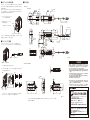
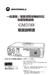
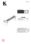
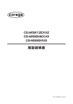
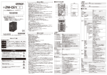
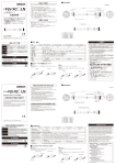
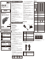
安全上の要点
形
ZW-SR□□
ファイバ同軸変位センサ センサヘッド
取扱説明書
このたびは、本製品をお買い上げいただきまして、まことにありがとうございます。
ご使用に際しては、次の内容をお守りください。
・ 電気の知識を有する専門家がお取り扱いください。
・この取扱説明書をよくお読みになり、十分にご理解のうえ、正しくご使用ください。
・この取扱説明書はいつでも参照できるように大切に保管してください。
以下に示すような項目は安全を確保する上で必要なことですので必ず守ってください。
1.設置環境について
・引火性、爆発性ガスの環境では使用しないでください。
・操作や保守の安全を確保するため、高電圧機器や動力機器から離して設置してください。
2.電源および配線について
電源および配線については専用コントローラ
(形ZW-CE1□□/形ZW-C1□□□)
の取扱
説明書の安全上の要点に従ってください。
・取付ネジは、本書にて記載している規定トルクで確実に締め付けてください。
・次のことを行うときは、必ず本体の電源をOFFにしてください。故障の原因となります。
・ケーブルの接続、配線
・コネクタの取り付け/取り外し
・キャリブレーションROMの取り付け/取り外し
3.その他
・原子力や、人命に関わる安全回路には使用しないでください。
・本製品を分解、
修理、改造、加圧変形、焼却したりしないでください。
・廃棄するときは、産業廃棄物として処理してください。
・専用のコントローラ(形ZW-CE1□□/形ZW-C1□□□)と接続してください。専用品以外
を使用すると発火や破裂、
誤動作や故障の原因になります。
・異臭がする、本体が非常に熱くなる、煙が出るなどの異常が起こった場合、
すぐに使用を中
止し、電源を切った状態で当社支店・営業所までご相談ください。
・落下や強い衝撃を与えないでください。
・ロック機構のあるものは、必ずロックしていることを確認してからご使用ください。
・ファイバケーブルを切断しないでください。切断部のガラスで怪我をするおそれがあります。
ま
た切断すると正常に動作しません。
4.法規と規格
本センサは、以下のEMC指令とEN規格に従っています。
・EMC指令 : No.2004/108/EC
・EN規格 : EN61326
© OMRON Corporation 2014 All Rights Reserved.
安全上のご注意
●警告表示の意味
警告
注意
正しい取扱いをしなければ、
この危険のために、軽傷・中程
度の傷害を負ったり、万一の場合には重症や死亡にいたる
おそれがあります。
また、同様に重大な物的損害を受けるお
それがあります。
正しい取扱いをしなければ、
この危険のために、時に軽傷・
中程度の傷害を負ったり、
あるいは物的損害を受けるおそ
れがあります。
●警告表示
警告
安全を確保する目的で直接的または間接的に人体を
検出する用途に本製品は使用できません。
人体保護用の検出装置として本製品を使用しないで
ください。
注意
LED光を見続けるとごくまれに視力障害を起こすこと
があります。
LED光を直視しないでください。
製品が動作不能、
誤動作、
または性能・機器への悪影響を防ぐため、
以下のことを守ってください。
1.設置場所について
次のような場所には設置しないでください。
・周囲温度が定格の範囲を超える場所
・温度変化が急激な場所
(結露する場所)
・相対湿度が35∼85%RHの範囲を超える場所
・腐食性ガス、可燃性ガスがある場所
・塵埃、塩分、鉄粉がある場所
・振動や衝撃が直接加わる場所
・強い外乱光
(レーザ光、
アーク溶接光、紫外光など)
があたる場所
・直射日光があたる場所や暖房器具のそば
・水・油・化学薬品の飛沫やミスト雰囲気がある場所
・強磁界、強電界がある場所
2.電源および接続、配線について
フレームグランド端子を接地してください。
・市販のスイッチングレギュレータをご使用の際は、
・電源ラインにサージがある場合、
使用環境に応じてサージアブソーバを接続してご使用ください。
・配線後は電源を投入する前に、電源の正誤、負荷短絡などの誤接続の有無、負荷電流の
適否について確認を行ってください。誤配線などで故障するおそれがあります。
・指定された電圧でご使用ください。定格を超える電圧や交流電圧を印加すると、回路部品
が焼損・破裂するおそれがあります。
・センサヘッドとコントローラ間のファイバケーブルの延長には、
オプション品の延長用ファイバケ
ーブル( 形ZW-XF□□R )
を使用してください。延長用ファイバケーブルには、全長
2m/5m/10m/20m/30mの5種類があります。標準ファイバケーブルと延長用ファイバケーブ
ルを合わせた長さは最大32m以下にしてください。
ファイバケーブルの延長は1本のみです。
・ファイバケーブルの取り扱いについて
以下の事項を守ってご使用ください。
・ファイバケーブルの曲げ半径は、20mm以上で使用してください。
・ファイバコネクタの根元部分に、曲げによるストレスがかからないようにしてください。
・ファイバケーブルを強く引っ張らないでください。
・ファイバケーブルを踏んだり、重いものを載せないでください。
・センサヘッドとキャリブレーションROMは、必ず同一のシリアルNo.の組み合わせで使用してく
ださい。異なるシリアルNo.同士では正しく動作しません。
・ファイバケーブルを外している場合は、付属の保護キャップをコントローラ側、
ファイバケーブル
側両方のコネクタに必ず装着してください。保護キャップを外したまま放置すると、異物付着
により誤動作のおそれがあります。
3.ウォームアップについて
電源投入後、30分以上経過してからご使用ください。電源投入直後は回路が安定してい
ませんので、測定値が徐々に変化することがあります。
4.保守点検について
・センサヘッドやファイバケーブル、
コントローラの清掃には、
シンナー、
ベンジン、
アセトン、灯油類
は使用しないでください。
センサヘッド、
ファイバケーブル、
コントローラの投受光部に大きなゴミ
やホコリが付いた場合は、
ブロアブラシ
(カメラレンズ用)
で吹き飛ばしてください。呼気で吹き
飛ばすことは避けてください。小さなゴミやホコリ、油脂よごれは柔らかい布
(レンズクリーナな
ど)
で、
ていねいにふき取ってください。強くふくことは避けてください。投受光部に傷がつくと、
誤動作や測定誤差の原因になります。
・ファイバケーブルの端面には触れないでください。性能劣化の原因となります。触れたり、汚
れたりした場合は、市販の専用ファイバコネクタクリーナまたは乾いた柔らかい布で汚れを拭
き取ってください。
なお、
アルコールをしみこませた布は使用しないでください。汚れが再付着
する恐れがあります。
なお、
ファイバコネクタクリーナは、下記の製品を推奨します。
部位
センサヘッド側
ファイバコネクタ
品目
型番
OPTIPOP R1
ATC-RE-01
メーカ
エヌ・ティ
・ティ
・アドバンス
テクノロジ株式会社
■定格/性能
仕様
項目
形ZW-SR07
形ZW-SR20
形ZW-SR40
測定中心距離
7mm
20mm
40mm
測定範囲
±0.3mm
±1mm
±6mm
静止分解能 *1
0.01μm
0.02μm
0.08μm
±1.1μm
±1.6μm
±9.3μm
スポット径
Near
φ20μm
φ45μm
φ90μm
*3
Center
φ18μm
φ40μm
φ80μm
Far
φ20μm
φ45μm
φ90μm
リニアリティ *2
測定周期
500μs∼10ms
使用周囲照度
物体面照度10,000Lx以下:白熱ランプ
周囲温度範囲
周囲湿度範囲
保護構造
IP40(IEC60529)
振動
(耐久)
10∼150Hz
(片振幅0.35mm)X/Y/Z各方向 80分
衝撃
(耐久)
150m/s2 6方向、各3回
(上下・左右・前後)
温度特性 *4
ストレート部分
3
2
4
キャリブレーションROM:PC
ファイバケーブル長
0.3m、2m(耐屈曲ケーブル)
ファイバケーブル最小曲げ半径
20mm
1分間
耐電圧(キャリブレーションROM) ケースと端子一括間:AC1000V、50/60Hz、
5
約130g
(筐体、
ファイバケーブル合計)
質量
光を投光・受光します。
2
シリアルNo.
シリアルNo.です。
同一シリアルNo.のキャリブレーションROMとの組み合わ
せのみ使用できます。
センサヘッドとファイバケーブルとの接合部です。
(取り外しはできません)
4
ファイバケーブル
コントローラと光信号をやりとりするファイバです。
5
ファイバコネクタ
コントローラとファイバケーブルとの接続コネクタです。
●キャリブレーションROM
センサヘッドと1
:
1で対応する専用のROMで、
センサヘッドに同梱されています。
コントローラに接続して使用します。
1
1
シリアルNo.
機能
シリアルNo.です。
同一シリアルNo.のセンサヘッドとの組み合わせのみ使用
できます。
取扱説明書、
キャリブレーションROM固定用ネジ
(M2)
、
ご使用上の注意
機能
投受光部
番号 名称
4.8μm/℃
(3.8μm/℃)
(250Vメガにて)
絶縁抵抗(キャリブレーションROM) ケースと端子一括間:20MΩ
1
ファイバ接合部
1.5μm/℃
ファイバケーブル被覆部:PVC
付属品
3
0.6μm/℃
筐体:アルミダイカスト
材質
ライトアングル部分
番号 名称
動作時/保存時:35∼85%
(だだし、結露しないこと)
●センサヘッド
1
動作時:0∼+50℃ 保存時:-15∼+60℃
(ただし、氷結・結露しないこと)
(0.45μm/℃) (1.0μm/℃)
■各部の名称と機能
使用上の注意
* 8 9 0 0 1 8 3 - 2 A *
・コントローラ側ファイバコネクタの清掃にはオプション品形ZW-XCLをご使用ください。
・ファイバケーブルおよびファイバコネクタは、短時間であっても保護キャップを外した状態で放
置しないでください。端面に汚れが付着し、性能劣化の原因になります。
・ファイバケーブルの抜き差しを行った場合は、
センサヘッドの校正を行ってください。
センサヘッ
ドの校正の方法は、
ユーザーズマニュアルをご参照ください。
5.対象物について
対象物の材質・形状によって、測定できない場合や精度がでない場合があります。
(透明な
部材、反射率の極端に低い材質、
スポット径よりも小さな対象物、曲率の大きな対象物、大
きく傾斜した対象物、表面に薄膜のついた対象物など)
6.周囲の照明の影響
センサヘッドの投受光部に強い照明があたる設置は避けてください。
また、
ワークに光沢がある場合、照明光が映り、誤動作することがあります。
その場合には照
明を覆うなどして映り込みを防いでください。
7.
空気のゆらぎの影響
センサヘッド周辺のゆっくりとした空気のゆらぎの影響で測定値がばらつくことがあります。
こ
のような場合には、センサヘッド周辺をカバーでおおってください。
8.計測範囲外の動作について
本センサは高感度化しているため、計測範囲外
(近距離側)
で誤動作が発生する場合があ
ります。
このような場合は、露光時間を短くすることで解消される場合があります。
9.修理対応範囲について
ファイバ折れ、
レンズや筐体損傷などによるその他の部品交換は、
修理対応不可となります。
10.コントローラとセンサヘッド・延長用ファイバケーブルとの接続について
銘鈑に「AR」
と記載してあるコントローラに、銘鈑に「AR」
と記載されていないセンサヘッド
および延長用ファイバケーブルを接続される場合は接続エラーとなります。接続エラーが発
生した場合は、
当社支店・営業所までご相談ください。
11.ライ
トアングル部分について
「各部の名称と機能」に記載の投受光部分含む先端のライ
トアングル部分に大きな力や
衝撃を加えないでください。加えた場合、接続しているストレート部分(「各部の名称と機能」
に記載のシリアルNo.を明記している部品全体)との接続がずれて、計測性能が劣化する
恐れがあります。
*1 当社標準の鏡面対象物を測定中心距離にて平均回数 4096 回で測定した場合の実力値
輸出管理貿易令対応コントローラ(形 ZW-CE1□T/ 形 ZW-C1□□T)と接続した場合は、
センサヘッド、平均回数に関わらず、最小分解能は 0.25μm となります。
*2 当社標準の鏡面対象物を測定した場合の理想直線に対する誤差
上記以外の対象物を測定した場合のリニアリティの参考値は下表のとおりです。
形ZW-SR07
ガラス
±1.1μm
SUS BA
±1.2μm
白色セラミック ±1.6μm
形ZW-SR20
±1.6μm
±1.8μm
±1.9μm
形ZW-SR40
±9.3μm
±9.3μm
±11.0μm
*3 測定エリア内の中心光強度の 1/e2
(13.5%)
で定義した実力値
*4 センサヘッドと対象物の間をアルミ治具で固定し、センサヘッドとコントローラを同一温度環境に
設置した場合の測定中心距離における温度特性。
( ) 内はアルミ治具自体の膨張収縮の影響を差し引いた換算値。
■外形寸法図
センサヘッド
24
24
12
M2ネジ
4- 3.5 (取付穴)
基準面
43±0.1
43
16±0.1
16
16
ファイバケーブル (
2.0)
締付けトルク:0.54N・m以下
締め付けトルク:0.15N・m 以下
24
64
ファイバコネクタ
40
10
24
24
(2)付属の M2 ネジで、キャリブレーション
ROM を固定します。
64
23.6
(1)コントローラの ROM コネクタに、キャリ
ブレーション ROM を接続します。
4-M3
取付基準面
4
取付穴加工寸法
4 ±0.1
コントローラに、キャリブレーション ROM を接続します。キャリブレーション ROM の挿抜
は、必ずコントローラの電源を切った状態で行ってください。電源 ON のまま行うと故
障の原因となります。
キャリブレーションROMとセンサヘッドは、各々1
:
1で対応しています。接続時には、
キャリ
ブレーションROMとセンサヘッドのシリアルNo.を必ず合わせてください。異なるシリアル
No.同士で動作させると、正常な測定を行いません。
16±0.1
■キャリブレーションROMの接続
■ファイバケーブルの接続
23.6
コントローラのファイバコネクタに、センサヘッドのファイバケーブルを接続します。
(1)コントローラのファイバコネクタ、
およびファイバケーブルの保護キャップを外します。
8.5
投受光軸
測定端
NEAR
測定中心
CENTER
測定端
FAR
24
ファイバコネクタ
注:保護キャップは捨てずに保管してください。
23.6
12
12
測定中心
CENTER
ファイバコネクタ
ご承諾事項
キャリブレーションROM
(図2)
2.5 取付穴
1
3
ファイバ
コネクタ
図 2、図 3 の「×」の状態では、光信号の伝達が行えず、正しい測定がで
きません。必ず「○」の状態になっていることを確認してください。
14
6.9
7
ファイバ
ケーブル
突起部
16.5
ネジ部
5
(図3)
19
溝部
当社商品は、一般工業製品向けの汎用品として設計製造されています。従いまして、次に
掲げる用途での使用を意図しておらず、
お客様が当社商品をこれらの用途に使用される際
には、当社は当社商品に対して一切保証をいたしません。
ただし、次に掲げる用途であって
も当社の意図した商品用途の場合や特別の合意がある場合は除きます。
(a) 高い安全性が必要とされる用途
(例:原子力制御設備、燃焼設備、航空・宇宙設備、鉄
道設備、昇降設備、娯楽設備、医用機器、安全装置、
その他生命・身体に危険が及び
うる用途)
(b) 高い信頼性が必要な用途
(例:ガス・水道・電気等の供給システム、24時間連続運転
システム、決済システムほか権利・財産を取扱う用途など)
(c) 厳しい条件または環境での用途
(例:屋外に設置する設備、化学的汚染を被る設備、
電磁的妨害を被る設備、振動・衝撃を受ける設備など)
(d) カタログ等に記載のない条件や環境での用途
2.6
(2)ファイバコネクタの溝部に、ファイバケーブルの突起部を合わせ、押し込みなが
らネジ部を右へ回します(図 1)
。
(図1)
(単位 : mm)
1.8
保護キャップ
M
0.3
1
6
33
3.5
7
27.4
(単位 : mm)
*センサヘッド (形 ZW-SR07/SR20/SR40) の同梱品です。必ず同一シリアルNo.同士のセンサヘッドとキャリブレーションROM
を組み合わせでご使用ください。
*(a)から(d)に記載されている他、本カタログ等記載の商品は自動車
(二輪車含む。以下同
じ)
向けではありません。自動車に搭載する用途には利用しないで下さい。自動車搭載
用商品については当社営業担当者にご相談ください。
*上記は適合用途の条件の一部です。当社のベスト、総合カタログ、データシート等最新版
のカタログ、
マニュアルに記載の保証・免責事項の内容をよく読んでご使用ください。
インダストリアルオートメーションビジネスカンパニー ●製品に関するお問い合わせ先
お客様相談室
3.6
保護キャップ
L
7
20
40
42
注意ラベル
基準面
(注1)
形式 /TYPE
ZW-SR07
ZW-SR20
ZW-SR40
50
24
キャリブレーション ROM は常に接続した状態でご使用ください。キャリブレーション ROM
が接続されていない場合、エラーが表示されます。
12
32.5
ROMコネクタ
M (注1) M (注1)
L (注1)
キャリブレーションROM
0120-919-066
クイック
オムロン
携帯電話・PHS・IP電話などではご利用いただけませんので、
下記の電話番号へおかけください。
電話
055-982-5015(通話料がかかります)
■営業時間:8:00∼21:00 ■営業日:365日
●FAXやWebページでもお問い合わせいただけます。
FAX
055-982-5051 / www.fa.omron.co.jp
●その他のお問い合わせ
納期・価格・サンプル・仕様書は貴社のお取引先、または貴社
担当オムロン販売員にご相談ください。
オムロン制御機器販売店やオムロン販売拠点は、Webページで
ご案内しています。
A u 2013年9月
PRECAUTIONS FOR SAFE USE
Model
ZW-SR□□
Sensor Head for Fiber Coaxial Displacement Sensor
INSTRUCTION SHEET
Thank you for selecting OMRON product. This sheet primarily
describes precautions required in installing and operating the product.
Before operating the product, read the sheet thoroughly to acquire
sufficient knowledge of the product. For your convenience, keep the
sheet at your disposal.
TRACEABILITY INFORMATION:
Representative in EU:
Omron Europe B.V.
Wegalaan 67-69
2132 JD Hoofddorp,
The Netherlands
Manufacturer:
Omron Corporation,
Shiokoji Horikawa, Shimogyo-ku,
Kyoto 600-8530 JAPAN
Ayabe Factory
3-2 Narutani, Nakayama-cho,
Ayabe-shi, Kyoto 623-0105 JAPAN
The following notice applies only to products that carry the CE mark:
Notice:
This is a class A product. In residential areas it may cause radio
interference, in which case the user may be required to take adequate
measures to reduce interference.
© OMRON Corporation 2014 All Rights Reserved.
PRECAUTIONS ON SAFETY
●Meanings of Signal Words
WARNING
CAUTION
Indicates a potentially hazardous situation which, if
not avoided, will result in minor or moderate injury, or
may result in serious injury or death. Additionally,
there may be significant property damage.
Indicates a potentially hazardous situation which, if
not avoided, may result in minor or moderate injury or
in property damage.
●Alert Statements in This Sheet
WARNING
This product is not designed or rated for ensuring safety of
persons either directly or indirectly. Do not use it for such
purposes.
CAUTION
Looking into the LED light continuously may occasionally
cause visual impairment.
Do not look directly into the LED light.
Please observe the following precautions for safe use of the products.
1.Installation Environment
• Do not use the product in environments where it can be exposed to
inflammable/explosive gas.
• To secure the safety of operation and maintenance, do not install the product close to
high-voltage devices and power devices.
2.Power Supply and Wiring
For details on power supply and wiring, refer to PRECAUTIONS FOR SAFE USE on the
Instruction Sheet of the dedicated Controller (ZW-CE1□□/ZW-C1□□□).
• Tighten the mounting screw to the torque specified in this instruction sheet.
• Always turn off the power of the main unit before taking the following actions. Not
doing so may result in malfunction.
• Connecting or wiring the cable
• Mounting or removing the connector
• Mounting or removing the Calibration ROM
3.Others
• Do not use in safety circuits for atomic energy or that are critical for human life.
• Do not attempt to disassemble, deform by pressure, incinerate, repair, or modify this
product.
• When disposing of the product, treat as industrial waste.
• Connect the Sensor Head to the dedicated Controller (ZW-CE1□□/ZW-C1□□□).
Use of other devices may result in fire, explosion, malfunction or failure.
• If you notice an abnormal condition such as a strange odor, extreme heating of the unit,
or smoke, immediately stop using the product, turn off the power, and consult your
dealer.
• Do not drop or impose shock on the product.
• Ensure that all components which have locking mechanisms are locked before using the
product.
• Do not cut the fiber cable. An injury may result due to the cutting area of the glass. In
addition, the Sensor may fail to work properly if the cable is cut.
4.Regulations and standards
This sensor complies with EMC directive and EN standards as follows:
•EMC directive: No.2004/108/EC
•EN standard: EN61326
PRECAUTIONS FOR CORRECT USE
Observe the following to prevent failure, malfunctioning, and adverse effects on
performance and the device.
1.Installation site
Do not install in the following locations:
• Locations where the ambient temperature exceeds the rated temperature range.
• Locations subject to sudden temperature changes (where condensation will form).
• Locations where the relative humidity is below or above 35 to 85% RH.
• Locations where there are corrosive or flammable gases.
• Locations where there is dust, salt, or iron powder.
• Locations where the device will be subject to direct vibration or shock.
• Locations where there is strong scattered light (laser light, arc welding light, ultraviolet
light, etc.)
• Locations exposed to direct sunlight or next to a heater.
• Locations where there is splashing or spraying of water, oil, or chemicals.
• Locations where there is a strong electrical or magnetic field.
2.Power and cable connections
• When using a commercially available switching regulator, make sure that the Frame
ground terminal is grounded.
• If there are surges on your power line, connect a surge absorber as appropriate for your
conditions of use.
• Before turning on the power after the wiring is completed, verify that the power is correct,
that there are no incorrect connections such as a shorted load circuit, and that the load
current is suitable. Incorrect wiring may cause damage and failures.
• Use the product with the specified voltage. Applying a voltage or AC voltage that exceed
the rating may result in burning or explosion of circuit components.
• To extend the fiber cable between the Sensor Head and Controller, an optional extension fiber
cable (ZW-XF□□R) must be used. There are five fiber cable types; 2 m/5 m/10 m/20 m/30
m. The length that combines the standard fiber cable and extension fiber cable must be 32 m
or shorter. Only one fiber cable can be used for extension.
• Handling the fiber cable
Observe the following conditions.
• Use the fiber cable with the bending radius of at least 20 mm.
• Avoid stress being applied to the root of the fiber connector due to bending.
• Do not forcibly pull the fiber cable.
• Do not step on or put a heavy object on the fiber cable.
• Use the Sensor Head and Calibration ROM of the same serial number. Operation will fail
if those with different serial numbers are used.
• When the fiber cable is not connected, be sure to attach the provided protective caps to the
connectors of both the Controller and fiber cable sides. Leaving the product without the
protective caps may result in malfunction caused by adhesion of a foreign material.
3.Warming Up
After turning on the power supply, allow the Controller to stand for at least 30 minutes
before use. The circuits are unstable immediately after the power supply is turned on and
attempting measurement may result in inconsistent measurement values.
4.Maintenance
• Do not use thinner, benzene, acetone or kerosene to clean the Sensor Head, fiber cable or
Controller. If considerable foreign matter or dust collects on the Sensor Head, fiber cable, or
receiver/emitter of the Controller, use a blower brush (for camera lenses) to blow off the
foreign matter. Avoid blowing it off with your breath. For a small amount of foreign matter
or dust, gently wipe with a soft cloth. Do not wipe hard. If the receiver/emitter is damaged,
malfunction or measurement error may result.
• Do not touch the end face of the fiber cable. It may result in deterioration in performance.
If it is touched or contaminated, wipe out contamination with a commercial fiber
connector cleaner or soft cloth. Do not use a cloth containing alcohol. Doing so may
cause adhesion of contamination again.
Location
Product name
Fiber connector at
OPTIPOP R1
the Sensor Head side
Model No.
ATC-RE-01
Manufacturer
NTT Advanced
Technology Corporation
• Use an optional ZW-XCL to clean the fiber connector of the controller side.
• Do not leave the fiber cable and fiber connector with the protective cap removed even for
a short period of time. Adhesion of contamination on the end face will occur, resulting in
deterioration in performance.
• After connection/disconnection of the fiber cable, perform calibration of the Sensor
Head. For details on Sensor Head calibration, refer to the User's Manual.
5.Sensing Object For Sensor Head
The product cannot accurately measure the following types of objects: Transparent
objects, objects with an extremely low reflective sensor ratio, objects smaller than the
spot diameter, objects with a large curvature, excessively inclined objects, objects with
thin film on the surface, etc.
6.Effects of surrounding lightings
Avoid installing the product at a location where the emitter/receiver of the Sensor Head is
exposed to strong lighting. If the workpiece has reflective surface, malfunction of the
product may occur due to light reflection. Prevent it by covering the lighting.
7. Influence of air current
Measured values may vary due to slow air current around the Sensor Head. In such case,
put a cover around the Sensor Head.
8.Operation beyond the measurement range
As this sensor is sensitive, malfunction may occur beyond the measurement range (near
side). In such case, shortening the exposure time may solve the problem.
9.Coverage of fixing support
Fixing support of component replacement by fiber breaking, lens damage and so on is not
accepted.
10.Connecting the Sensor Head and extension fiber cable to the Controller
A connection error occurs if the Controller with the word “AR” written on the label is
connected to the Sensor Head without “AR” on the label and the extension fiber cable.
When a connection error occurs, please consult to the branch of our company, and an
office.
11.Right-angle unit
If you make an excessive force or impact to right-angle unit(The part contains
Emitter/receiver of “Part Names and Functions”), It may develop into a gap between
right-angle unit and straight-unit(The part attaches serial No. of “Part Names and
Functions”).As a result, it may have a problem with measurement quality. Please be
careful not to make excessive force or impact to right-angle unit.
■Specifications
Specifications
Item
ZW-SR07
ZW-SR20
ZW-SR40
Measuring center distance
7 mm
20 mm
40 mm
Measuring range
±0.3 mm
±1 mm
±6 mm
Static resolution *1
0.01 μm
0.02 μm
0.08 μm
Linearity *2
±1.1 μm
±1.6 μm
±9.3 μm
20 μm dia.
45 μm dia.
90 μm dia.
18 μm dia.
40 μm dia.
80 μm dia.
20 μm dia.
45 μm dia.
90 μm dia.
Near
Spot
diameter *3 Center
Far
Measurement cycle
500 μs to 10 ms
Operating ambient illumination Object surface illumination: 10000 Lx max. (incandescent light)
Ambient temperature
range
Operating: 0 to +50°C, Storage: -15 to +60°C
Ambient humidity
range
Operating and storage: 35% to 85%
Degree of protection
IP40 (IEC60529)
Vibration resistance
10 to 150 Hz, 0.35-mm half amplitude 80 min each
(destructive)
in X, Y, and Z directions
Shock resistance
150m/s2 3 times each in six directions (up/down,
(destructive)
left/right, forward/backward)
(with no icing or condensation)
(with no condensation)
Temperature characteristic *4 0.6 μm/°C
■Part Names and Functions
1.5 μm/°C
(0.45 μm/°C) (1.0 μm/°C)
●Sensor Head
Material
4.8 μm/°C
(3.8 μm/°C)
Body: Aluminum die-cast
Fiber cable coating: PVC
Right-angle unit
Straight unit
3
1
2
4
Calibration ROM: PC
Fiber cable length
0.3 m, 2 m (Flex resistance cable)
Fiber cable minimum
20 mm
bending radius
Insulation resistance
5
Dielectric strength
No.
Name
Function
1
Emitter/receiver
Emits/receives light.
2
Serial No.
A serial number.
Calibration ROM with the same serial number is valid.
Fiber joint
A joint of the Sensor Head and fiber cable.
(Not detachable)
4
Fiber cable
A fiber that exchanges optical signals with the Controller.
5
Fiber connector
A connector that connects the Controller and fiber cable.
●Calibration ROM
The dedicated ROM for the Sensor Head. It is included in the Sensor Head.
Use it by connecting to the Controller.
1
No.
1
Name
Function
Serial No.
A serial number.
Between case and all terminals: 1000 VAC, 50/60 Hz, 1 min.
(Calibration ROM)
Weight
Approx. 130 g (total of the body and fiber cable)
Accessories
Instruction Sheet, Calibration ROM fixing screw (M2),
Precautions
Only the combination of the Sensor Head and
3
Between case and all terminals: 20 MΩ (250 VDC)
(Calibration ROM)
Only the combination of the Calibration ROM and
Sensor Head with the same serial number is valid.
*1 An actual figure when measured an OMRON-standard mirror surface object with average count of 4096
times at the measuring center distance.
When connecting the Export Trade Control Order compatible Controller (ZW-CE1□T/ZW-C1□□T),
the minimum resolution is 0.25 μm regardless of the Sensor Head and average count.
*2 Errors for an ideal straight line when an OMRON-standard mirror surface object is measured.
Reference values of the linearity when objects other than listed above are as follows:
Glass
SUS BA
White ceramic
ZW-SR07
±1.1 μm
±1.2 μm
±1.6 μm
ZW-SR20
±1.6 μm
±1.8 μm
±1.9 μm
ZW-SR40
±9.3 μm
±9.3 μm
±11.0 μm
*3 Actual figure defined at 1/e2 (13.5%) of the center optical strength within the measuring area.
*4 A temperature characteristic at the measuring center distance when securing the gap between
the Sensor Head and the object with an aluminum jig and installing the Sensor Head and
Controller under the same temperature.
The figure in the parentheses indicates a converted value after deduction of the effect of
expansion and shrinkage of the alminum jig itself.
■Dimensions
Mounting screw holes
(1) Connect the Calibration ROM to the
ROM connector of the Controller.
Standard surface
64
Tightening torque: 0.15 N·m max.
12
Standard surface
4-Dia.3.5 (Mounting holes)
16±0.1
M2 screw
24
23.6
24
(2) Secure the Calibration ROM with the
provided M2 screw.
4-M3
4
Sensor Head
43±0.1
43
16±0.1
16
Fiber cable (Dia.2)
16
Connect the Calibration ROM to the Controller.
A Calibration ROM and a Sensor Head are paired. Be sure to match the serial
numbers of the Calibration ROM and Sensor Head. Operating them with different
serial numbers will cause a measurement error.
4 ±0.1
■Connecting the Calibration ROM
Tightening torque:0.54N・m max.
Label CAUTION
24
64
40
8.5
Measurement end
NEAR
TYPE
ZW-SR07
ZW-SR20
ZW-SR40
Protective cap Fiber connector
L
7
20
40
M
0.3
1
6
24
42
Standard surface
Measurement center
CENTER
Measurement end
FAR
23.6
(Note 1)
Protective cap Fiber connector
L (Note 1)
M (Note 1)
23.6
50
24
Lightening &
receiving axis
Measurement center
CENTER
12
12
Connect the fiber cable of the Sensor Head to the fiber connector of the Controller.
(1) Remove the fiber connector of the Controller and protective cap of the fiber cable.
M (Note 1)
32.5
■Connecting the fiber cable
12
Use the Controller with the Calibration ROM always connected. An error will be
displayed if the Calibration ROM is not connected.
Fiber Connector
Dia.10
24
ROM connector
24
Calibration ROM
(Unit : mm)
Note: Be sure to keep the protective cap.
(Fig. 2)
Groove
Screw
No Good
(Fig. 3)
Good
No Good
Dia.2.5 Mounting hole
5
1
NEVER USE THE PRODUCT FOR AN APPLICATION INVOLVING
SERIOUS RISK TO LIFE OR PROPERTY WITHOUT ENSURING THAT THE
SYSTEM AS A WHOLE HAS BEEN DESIGNED TO ADDRESS THE RISKS,
AND THAT THE OMRON PRODUCT(S) IS PROPERLY RATED AND
INSTALLED FOR THE INTENDED USE WITHIN THE OVERALL
EQUIPMENT OR SYSTEM.
See also Product catalog for Warranty and Limitation of Liability.
3
Fiber connector
33
3.5
7
3.6
7
14
6.9
16.5
Optical signal transmission will fail with "No Good" connections as shown in
Fig. 2 and Fig. 3.
Make sure that the fiber cables are connected in "Good" connections as shown in
Fig. 2 and Fig. 3.
19
Fiber cable
Protruding
part
Good
Omron Companies shall not be responsible for conformity with any standards,
codes or regulations which apply to the combination of the Product in the
Buyer’s application or use of the Product. At Buyer’s request, Omron will
provide applicable third party certification documents identifying ratings and
limitations of use which apply to the Product. This information by itself is not
sufficient for a complete determination of the suitability of the Product in
combination with the end product, machine, system, or other application or
use. Buyer shall be solely responsible for determining appropriateness of the
particular Product with respect to Buyer’s application, product or system.
Buyer shall take application responsibility in all cases.
Calibration ROM
2.6
(Fig. 1)
Suitability for Use
1.8
(2) Align the protruding part of the fiber cable to the groove of the fiber connector, and
rotate the screw to the right while pushing the end of the fiber cable (Fig. 1).
27.4
(Unit : mm)
* Included in the Sensor Head (ZW-SR07/SR20/SR40) . Be sure to use the Sensor Head and Calibration ROM of the same serial
numbers.
OMRON Corporation
Tokyo, JAPAN
Industrial Automation Company
Contact: www.ia.omron.com
Regional Headquarters
OMRON EUROPE B.V.
Sensor Business Unit
Carl-Benz-Str. 4, D-71154 Nufringen, Germany
Tel: (49) 7032-811-0/Fax: (49) 7032-811-199
OMRON ELECTRONICS LLC
One Commerce Drive Schaumburg,
IL 60173-5302 U.S.A.
Tel: (1) 847-843-7900/Fax: (1) 847-843-7787
OMRON ASIA PACIFIC PTE. LTD.
No. 438A Alexandra Road # 05-05/08 (Lobby 2),
Alexandra Technopark,
Singapore 119967
Tel: (65) 6835-3011/Fax: (65) 6835-2711
OMRON (CHINA) CO., LTD.
Room 2211, Bank of China Tower,
200 Yin Cheng Zhong Road,
PuDong New Area, Shanghai, 200120, China
Tel: (86) 21-5037-2222/Fax: (86) 21-5037-2200
D r Se p , 2 0 1 3