1
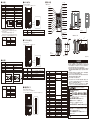
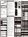
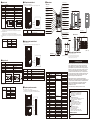
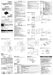
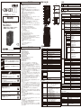
安全上の要点
形
ZW-CE1□□
ファイバ同軸変位センサ コントローラ
取扱説明書
このたびは,本製品をお買い上げいただきまして,まことにありがとうございます。
ご使用に際しては,次の内容をお守りください。
・電気の知識を有する専門家がお取扱いください。
・この取扱説明書をよくお読みになり,十分にご理解のうえ,正しくご使用ください。
・この取扱説明書はいつでも参照できるように大切に保管してください。
*
9 5 2 3 1 5 4
-
8 C *
© OMRON Corporation 2012 All Rights Reserved.
安全上のご注意
● 警告表示の意味
警告
正しい取扱いをしなければ、この危険のために、軽傷・中程度の
傷害を負ったり、万一の場合には重症や死亡にいたるおそれがあ
ります。また、同様に重大な物的損害を受けるおそれがあります。
注意
正しい取扱いをしなければ、この危険のために、時に軽傷・中
程度の傷害を負ったり、あるいは物的損害を受けるおそれがあり
ます。
● 警告表示
警告
安全を確保する目的で直接的または間接的に人体を検出する用途
に本製品は使用できません。
人体保護用の検出装置として本製品を使用しないでください。
分解すると、高い電圧の部分があり、感電の恐れがあります。また高温で
やけどのおそれがあります。
本体の分解、修理、改造、加圧変形、焼却などは絶対にしないでください。
注意
故障や発火のおそれがあります。
定格電圧を越えて使用しないでください。
破裂のおそれがあります。
AC電源では絶対に使用しないでください。
LED光を見続けるとごくまれに視力障害を起こすことがあります。
LED光を直視しないでください。
<前面>
以下に示すような項目は安全を確保する上で必要なことですので必ず守ってください。
1.設置環境について
・引火性、
爆発性ガスの環境では使用しないでください。
・操作や保守の安全を確保するため、高電圧機器や動力機器から離して設置してください。
2.電源および配線について
・過電流検知機能付き電源をご使用の場合はご注意ください。本センサの電源回路にはDC-DCコン
バータを使用しています。過電流検知機能付き電源の場合、突入電流により保護回路がはたらくこ
とがあります。
推奨電源 : 形S8VS-06024 (オムロン製 DC24V 2.5A 60W)
・定格電圧
(DC24V±10%)
を超える電圧や交流電源を使用しないでください。
・電源の逆接続はしないでください。
・オープンコレクタ出力は、負荷を短絡させないでください。
・負荷は定格以下で使用してください。
・高圧線、動力線と本製品の配線は別配線としてください。同一配線あるいは同一ダクトにすると誘
導を受け、
誤作動あるいは破損の原因になることがあります。
・フェイルセーフ回路などの十分な安全対策をして使用してください。
・配線時は、指定サイズの圧着端子を付けてください。撚り合わせただけの電線を直接電源や端子
台に接続しないでください。
されている直流電源装置から供給してください。
・電源は、高電圧が発生しないように対策(安全超低電圧回路)
・電源線の長さができるだけ短くなるように配線してください。
・D種接地
(接地抵抗100Ω以下)
をしてください。接地点はできるだけ近くし、使用する接地線の長さ
をできるだけ短くしてください。
・接地線は、他の機器と共用したり建物の梁に接続しないでください。悪影響を受ける可能性があり
ます。
・本製品は他の商品と一緒にせず、
単独の電源で使用してください。
・取付ネジは、
本書にて記載している規定トルクで確実に締め付けてください。
・次のことを行うときは、必ず本体の電源をOFFにしてください。故障の原因となります。
・ケーブルの接続、
配線
・コネクタの取り付け/取り外し
・キャリブレーションROMの取り付け/取り外し
3.その他
・原子力や、
人命に関わる安全回路には使用しないでください。
・本製品を分解、修理、
改造、加圧変形、
焼却したりしないでください。
・廃棄するときは、産業廃棄物として処理してください。
・専用の装置(センサヘッド、
キャリブレーションROM、
ファイバケーブル、
RS-232Cケーブル)を接続してく
ださい。専用品以外を使用すると発火や破裂、
誤動作や故障の原因になります。
・異臭がする、本体が非常に熱くなる、煙が出るなどの異常が起こった場合、
すぐに使用を中止し、電
源を切った状態で当社支店・営業所までご相談ください。
・落下や強い衝撃を与えないでください。
・ロック機構のあるものは、必ずロックしていることを確認してからご使用ください。
4.法規と規格
本センサは、以下のEMC指令とEN規格に従っています。
・EMC指令 : No.2004/108/EC
・EN規格 : EN61326
使用上の注意
製品が動作不能、
誤動作、
または性能・機器への悪影響を防ぐため、以下のことを守ってください。
1.設置場所について
次のような場所には設置しないでください。
・周囲温度が定格の範囲を超える場所
・温度変化が急激な場所
(結露する場所)
・相対湿度が35∼85%RHの範囲を超える場所
・腐食性ガス、
可燃性ガスがある場所
・塵埃、
塩分、鉄粉がある場所
・振動や衝撃が直接加わる場所
・強い外乱光
(レーザ光、
アーク溶接光、
紫外光など)
があたる場所
・直射日光があたる場所や暖房器具のそば
・水・油・化学薬品の飛沫やミスト雰囲気がある場所
・強磁界、
強電界がある場所
2.電源および接続、
配線について
・市販のスイッチングレギュレータをご使用の際は、
フレームグランド端子を接地してください。
・電源ラインにサージがある場合、
使用環境に応じてサージアブソーバを接続してご使用ください。
・配線後は電源を投入する前に、電源の正誤、負荷短絡などの誤接続の有無、負荷電流の適否につ
いて確認を行ってください。誤配線などで故障するおそれがあります。
・指定された電圧でご使用ください。定格を超える電圧や交流電圧を印加すると、回路部品が焼損・破
裂するおそれがあります。
・センサヘッドとコントローラ間のファイバケーブルの延長には、オプション品の延長用ファイバケーブル(形ZW-XF□□R)を使
用してください。延長用ファイバケーブルには、全長2m/5m/10m/20m/30mの5種類があります。標準ファイバケーブルと延長
用ファイバケーブルを合わせた長さは最大32m以下にしてください。ファイバケーブルの延長は1本のみです。
・センサヘッドとキャリブレーションROMは、必ず同一のシリアルNo.の組み合わせで使用してください。異
なるシリアルNo.同士では正しく動作しません。
・設定用ソフトウェアは専用のものを使用してください。指定外のものを使用すると誤動作のおそれがあり
ます。使用できる設定用ソフトウェアは、形SYSMAC-SE□□□L、形SYSMAC-ME□□□L、形
ZW-SW101の3形式です。
・各種データをコントローラ内蔵メモリにセーブ中は、
電源を切らないでください。
データが破損します。
ファイバケーブル側両方のコネクタに必
・ファイバケーブルを外している場合は、付属の保護キャップをコントローラ側、
ず装着してください。保護キャップを外したまま放置すると、異物付着により誤動作のおそれがあります。
・EtherCATケーブルを挿抜する際は、
キャリブレーションROMにストレスを与えないようにしてください。
3.ウォームアップについて
電源投入後、30分以上経過してからご使用ください。電源投入直後は回路が安定していませんので、
測定値が徐々に変化することがあります。
4.保守点検について
コントローラ側ファイバコネクタの清掃にはオプション品形ZW-XCLをご使用ください。
センサヘッドやファイ
バケーブル、
コントローラの清掃には、
シンナー、ベンジン、
アセトン、灯油類は使用しないでください。
センサ
ヘッド、
コントローラの投受光部に大きなゴミやホコリが付いた場合は、
ブロアブラシ
(カメラレンズ用)
で吹き
飛ばしてください。呼気で吹き飛ばすことは避けてください。小さなゴミやホコリ、油脂よごれは柔らかい布
(レンズクリーナなど)
で、
ていねいにふき取ってください。強くふくことは避けてください。投受光部に傷がつ
くと、誤動作や測定誤差の原因になります。
なお、
ファイバケーブル端面の清掃方法については、形ZW-S□□の取扱説明書を参照してください。
5.対象物について
対象物の材質・形状によって、測定できない場合や精度がでない場合があります。
( 透明な部材、反
射率の極端に低い材質、
スポット径よりも小さな対象物、曲率の大きな対象物、大きく傾斜した対象物、
表面に薄膜のついた対象物など)
6.周囲の照明の影響
センサヘッドの投受光部に強い照明があたる設置は避けてください。
また、
ワークに光沢がある場合、照明光が映り、誤動作することがあります。
その場合には照明を覆うな
どして映り込みを防いでください。
7.
空気のゆらぎの影響
センサヘッド周辺のゆっくりとした空気のゆらぎの影響で測定値がばらつくことがあります。
このような場
合には、センサヘッド周辺をカバーでおおってください。
8.計測範囲外の動作について
本センサは高感度化しているため、計測範囲外(近距離側)
で誤動作が発生する場合があります。
こ
のような場合は、
露光時間を短くすることで解消される場合があります。
9.コントローラとセンサヘッド・延長用ファイバケーブルとの接続について
銘板に「AR」
と記載してあるコントローラに、
銘板に「AR」
と記載されていないセンサヘッド及び延長用
ファイバケーブルを接続される場合は接続エラーとなります。接続エラーが発生した場合は、
当社支店・
営業所までご相談下さい。
<後面>
■各部の名称と機能
1
2
3
4
5
6
<後面>
<底面>
7
番号 名称
32 取付ネジ穴
8
9
10
11
16
17
20
21
28
29
26
24
13
14
31
15
27
30
25
<底面>
32
<前面>
●表示部
番号
1
2
3
4
5
6
7
8
9
10
11
12
13
14
15
機能
判定結果がHIGH
(HIGHしきい値<測定値)
のときに点灯します。
判定結果がPASS
(LOWしきい値≦測定値≦HIGHしきい値)
のときに
点灯します。
判定結果がLOW
(測定値<LOWしきい値)
のときに点灯します。
LOW表示灯
(橙)
STABILITY表示灯
(緑) 測定値が測定範囲内にあるときに点灯します。
測定範囲外にあるときに消灯します。
ゼロリセット設定時に点灯します。
ZERO表示灯
(緑)
測定可能時に点灯します。
ENABLE表示灯
(緑)
測定不可能時
(受光量過大または不足、測定範囲外、
キャリブレーション
ROM未接続、FUNモード非測定時)
は消灯します。
測定値や機能の名称を表示します。
メインデジタル
(赤)
測定値の補助的な情報や機能の設定値を表示します。
サブデジタル
(緑)
RUNモード時に点灯、FUNモード時に消灯します。
RUN表示灯
(緑)
THRESHOLD-L表示灯(橙) サブデジタルにLOWしきい値を表示しているときに点灯します。
THRESHOLD-H表示灯(橙) サブデジタルにHIGHしきい値を表示しているときに点灯します。
EtherCAT通信可能時に点灯します。
ECAT RUN表示灯(緑)
EtherCAT機器と接続したときに点灯、通信(データ入力)時に点滅します。
L/A IN表示灯(緑)
EtherCAT機器と接続したときに点灯、通信(データ出力)時に点滅します。
L/A OUT表示灯(緑)
ECAT ERROR表示灯(赤) EtherCAT通信異常時に点灯します。
名称
(発光色)
HIGH表示灯
(橙)
PASS表示灯
(緑)
●操作部
番号
16
17
18
19
20
名称
機能
ZERORST/ESCキー
動作モードにより、機能は異なります。
←
(LEFT)
キー
→
(RIGHT)
キー
↑
(UP)
キー
↓
(DOWN)
キー
ZERO/SETキー
モード切替キー
ノードアドレス設定スイッチ EtherCAT通信機器としての局アドレス設定に使用します。
設定範囲は01∼99です。
●コネクタ/端子部
番号
21
22
23
24
25
26
27
28
29
30
名称
RS-232Cコネクタ
機能
コントローラをネジ固定する際に使用します。
項目
19
12
23
機能
コントローラをDINレールに固定する際に使用します。
■定格/性能
18
22
番号 名称
31 DINレール取付フック
機能
PLCやパソコンとRS-232C接続するときに使用します。
RS-232Cケーブルは、必ず下記の専用品をご使用ください。
専用品以外のケーブルを使用すると、誤動作や故障の原因となります。
・PLC/プログラマブルターミナル接続用:形ZW-XPT2
・パソコン接続用:形ZW-XRS2
Ethernetコネクタ
PLCやパソコンとEthernet接続するときに使用します。
Ethernetケーブルは、次の条件を満たす市販のケーブルをご用意ください。
・カテゴリ5e以上、長さ30m以下
・RJ45コネクタ
(8ピンモジュラジャック)
・1
:
1で接続する場合:クロスケーブルを選択
・ネットワークHUB経由で接続する場合:ストレートケーブルを選択
EtherCATコネクタ(入力) EtherCAT対応機と接続するときに使用します。
EtherCATケーブルは推奨のものをご使用ください。
EtherCATコネクタ(出力) EtherCAT対応機と接続するときに使用します。
EtherCATケーブルは推奨のものをご使用ください。
24V入力端子台
コントローラのDC24V電源を接続します。
32極拡張コネクタ
パラレルI/O(判定出力、ALARM出力、BUSY出力、ENABLE出力、
ZERO入力、RESET入力、TIMING入力、LED OFF入力、
バンク番号出力、
バンク番号選択入力)を接続します。
アナログ出力端子台
アナログ電圧出力、
アナログ電流出力を接続します。
ファイバコネクタ
ファイバケーブルを接続します。
ROM接続コネクタ
キャリブレーションROMを接続します。
フレームグランド端子
フレームグランド用の端子です。
接地線を接続します。
仕様
形ZW-CE10
形ZW-CE15
入出力タイプ
NPN
PNP
センサヘッド接続台数
1台
センサヘッド互換性
あり
測定用光源
白色LED
メインデジタル表示
セグメント
11セグメント赤色表示、6桁
サブデジタル表示
表示
11セグメント緑色表示、6桁
HIGH(橙色)、PASS(緑色)、LOW(橙色)、STABILITY
状態表示灯
LED表示
(緑色)、ZERO(緑色)、ENABLE(緑色)、THRESHOLD-H
(橙色)、THRESHOLD-L(橙色)、RUN(緑色)
ECAT RUN(緑色)、L/A IN(Link/Activity IN)
(緑色)
EtherCAT表示灯
L/A OUT(Link/Activity OUT)
(緑色)、ECAT ERR(赤色)
100BASE-TX/10BASE-T
外部インタ Ethernet
EtherCAT専用プロトコル100BASE-TX
EtherCAT
フェース
最大115,200bps
RS-232C
アナログ アナログ電圧出力(OUT1V) -10V∼+10V、出力インピーダンス:100Ω
出力端子台 アナログ電流出力(OUT1A) 4mA∼20mA、最大負荷抵抗:300Ω
32極拡張 判定出力
トランジスタ出力方式
コネクタ (HIGH1/PASS1/LOW1) 出力電圧:DC21.6∼30V
ビジー出力(BUSY1)
負荷電流:50mA以下
アラーム出力(ALARM1) ON時残留電圧:1.2V以下
イネーブル出力(ENABLE) OFF時漏れ電流:0.1mA以下
LED OFF入力
DC入力方式
(LED OFF1)
入力電圧:DC24V±10%(DC21.6∼26.4V)
ゼロリセット入力(ZERO1) 入力電流:7mA Typ. (DC24V)
タイミング入力(TIMING1) ON電圧/ON電流:19V/3mA以上
リセット入力(RESET1) OFF電圧/OFF電流:5V/1mA以下
バンク 選択中バンク出力 トランジスタ出力方式
(BANK_OUT
出力電圧:DC21.6∼30V
1∼3)
負荷電流:50mA以下
ON時残留電圧:1.2V以下
OFF時漏れ電流:0.1mA以下
バンク選択入力 DC入力方式
(BANK_SEL
入力電圧:DC24V±10%(DC21.6∼26.4V)
1∼3)
入力電流:7mA Typ. (DC24V)
ON電圧/ON電流:19V/3mA以上
OFF電圧/OFF電流:5V/1mA以下
露光時間
主な機能
オート/固定
測定周期
500μs∼10ms
材質指定
標準/鏡面/粗面
測定アイテム
高さ/厚み/演算
フィルタ処理
メディアン/平均/微分/ハイパス/ローパス/バンドパス
出力
スケーリング/各種ホールド/ゼロリセット/測定値ロギング
表示
測定値/しきい値/アナログ出力電圧値または電流値/
判定結果/分解能/露光時間
設定登録数
最大8バンク
タスク処理
マルチタスク
(1バンクあたり最大4タスク)
システム
セーブ/初期化/測定情報表示/通信設定/センサヘッド校正/
キーロック/ゼロリセットメモリ/タイミングキー入力
電源電圧
定格
DC21.6V∼26.4V(リップル含む)
消費電流
600mA以下
絶縁抵抗
リード線一括とFG端子間:20MΩ
(250Vメガにて)
耐電圧
リード線一括とFG端子間:AC500V、50/60Hz、
1分間
保護構造
耐環境性
IP20(IEC60529)
振動(耐久)
10∼55Hz(片振幅0.35mm)、X/Y/Z各方向 50分
6方向、各3回(上下・左右・前後)
衝撃(耐久)
150m/s2、
動作時:0∼+40℃、保存時:-15∼+60℃
周囲温度範囲
(ただし、氷結・結露しないこと)
動作時/保存時:35∼85%(ただし、結露しないこと)
周囲湿度範囲
D種接地(接地抵抗100Ω以下) *従来の第三種接地
接地
筐体:PC
材質
約750g(本体のみ)、約150g(パラレルケーブル)
質量
パラレルケーブル(形ZW-XCP2E)、取扱説明書、会員登録シート
付属品
輸出管理貿易令対応コントローラ
(形 ZW-CE1 □T)
をご用意しております。
このコントローラをご使用の場合は、接続されるセンサヘッド、平均回数に関わらず、最小分解能は 0.25μmとなります。
●EtherCAT通信仕様
仕様
IEC 61158 Type12
100BASE-TX (IEEE802.3)
RJ45×2 EtherCAT IN:EtherCAT入力 EtherCAT OUT:EtherCAT出力
カテゴリ5以上ツイストペアケーブル
(アルミテープと編組の二重遮へいシールドケーブル、
ストレートを推奨)
通信距離最大値
ノード間距離 100m以内
プロセスデータ
可変PDOマッピング(variable PDO mapping)
メールボックス(CoE)
エマージェンシーメッセージ、SDOリクエスト、SDOレスポンス、SDOインフォメーション
ディストリビューテッドクロック DCモードによる同期
LED表示
L/A IN (Link/Activity IN)×1 L/A OUT(Link/Activity OUT)×1
ECAT RUN×1 ECAT ERR×1
項目
通信規格
物理層
コネクタ
通信媒体
■入力回路
■外形寸法図
■24V入力端子台
形ZW-CE15
入力タイプ
NPN
PNP
入力電圧
DC24V±10%(21.6∼26.4V)
DC24V±10%(21.6∼26.4V)
入力電流
7mA Typ. (DC24V)
7mA Typ. (DC24V)
ON電圧/ON電流*1
19V以上/3mA以上
19V以上/3mA以上
OFF電圧/OFF電流*2 5V以下/1mA以下
5V以下/1mA以下
ONディレイ
0.1ms以下
0.1ms以下
OFFディレイ
0.1ms以下
0.1ms以下
サブデジタル 表示灯
HIGH 表示灯
THRESHOLD-H 表示灯
PASS 表示灯
RUN 表示灯
STABILITY 表示灯
ノードアドレス設定スイツチ
ZERO 表示灯
内部回路図 *3
ROM取付ネジ穴
M2 有効深さ2
各入力端子
+
910Ω
1000pF
910Ω
3.3kΩ
RS-232C コネクタ
1
2
内部回路
+
内部回路
1000pF
3.3kΩ
フアイバ コネクタ
Ethernet コネクタ
COM_IN1/2
COM_IN1/2
124
ENABLE 表示灯
各入力端子
128
THRESHOLD-L 表示灯
LOW 表示灯
ROM接続コネクタ
EtherCAT コネクタ (入力)
32極拡張コネクタ
アナログ出力端子台
端子番号
信号名
内容
1
2
DC24V(-)
DC24V(+)
電源用0V入力
電源用24V入力
10.2
フレームグランド端子取付ネジ
M4-L6
21.4
72
DINレール取付フック
24V入力端子台
フレームグランド端子取付ネジ穴
M4 有効深さ7
●パラレルケーブル
EtherCAT コネクタ (出力)
端子名
COM_IN1
COM_IN2
入力信号名
TIMING1
RESET1
BANK1
BANK2
■アナログ出力端子台
ZERO1
LED_OFF1
BANK3
アナログ出力に使用します。
適合コード仕様:AWG18∼28、先端処理長さ:7mm
127.5
6
*1 ON 電圧 /ON 電流
OFF→ON 状態にさせる電圧値または電流値のことです。
ON 電圧の値は、COM_IN1/2 と各入力端子間の電位差になります。
*2 OFF 電圧 /OFF 電流
ON→OFF 状態にさせる電圧値または電流値のことです。
OFF 電圧の値は、COM_IN1/2 と各入力端子間の電位差になります。
*3 COM_IN
(入力コモン)
と、各入力信号の接続対応表を以下に示します。
34.9
形ZW-CE10
40.8
仕様
形式
メインデジタル 表示灯
●コントローラ
4- Ø 4.5
6
(13.1)
+140.0
2110 0
40
7
70
70 ±0.1
B1
B16
取付ネジ穴
4-M 4 深さ6.0 MAX.
14.5
A1
(35.45)
項目
DC24V電源の入力に使用します。
適合コード仕様:AWG12∼26、先端処理長さ:10mm
A16
43 ±0.1
43
取付穴加工寸法
締付けトルク:1.2N・m
1
2
3
■出力回路
項目
仕様
形式
形ZW-CE10
入力タイプ
NPN
PNP
DC21.6∼30V
DC21.6∼30V
負荷電流
ON残留電圧
50mA以下
1.2V以下
50mA以下
1.2V以下
ON漏れ電流
0.1mA以下
0.1mA以下
内部回路図 *1
内部回路
4
5
6
ご承諾事項
形ZW-CE15
出力電圧
各出力端子
L
負荷
+
COM_OUT1/2
内部回路
+
負荷
COM_OUT1/2
端子番号
信号名
内容
1
2
3
4
OUT1(V)
OUT1(A)
センサヘッド1のアナログ電圧出力 測定値を±10Vで出力
センサヘッド1のアナログ電流出力 測定値を4∼20mAで出力
センサヘッド1のアナログ出力用0V
使用しません
5
6
NC
OUT1 0V
NC
NC
使用しません
使用しません
L
各出力端子
*1 COM_OUT( 出力コモン ) と、各出力信号の接続対応表を以下に示します。
端子名
COM_OUT1
COM_OUT2
■32極拡張コネクタ
出力信号名
HIGH1
PASS1
BANK_OUT1
BANK_OUT2
LOW1
ALARM1
BUSY1
BANK_OUT3
判定出力や制御入力などに使用します。
適合コネクタ:FX2Bシリーズ
(ヒロセ電機株式会社)
2mコード付きの32極拡張コネクタ用パラレルケーブル
(形ZW-XCP2E)
を同梱しています。
ENABLE
B16
B1
(単位:mm)
A16
A1
端子番号
A1
A2
信号名
NC
BANK_SEL3
内容
使用しません
バンク選択入力
形ZW-XCP2Eのコード色
茶
赤
A3
A4
A5
BANK_SEL2
BANK_SEL1
COM_IN2
入力用COM2
橙
黄
緑
A6
A7
A8
NC
NC
NC
A9
A10
A11
NC
NC
NC
白
黒
茶
A12
A13
A14
NC
NC
NC
赤
橙
黄
A15
A16
B1
NC
NC
BANK_OUT3
バンク番号出力
緑
青
茶
B2
B3
B4
BANK_OUT2
BANK_OUT1
COM_OUT2
出力用COM2
赤
橙
黄
B5
B6
B7
ENABLE
BUSY1
ALARM1
ENABLE出力
センサヘッド1のBUSY出力
センサヘッド1のALARM出力
B8
B9
B10
LOW1
PASS1
HIGH1
B11
B12
B13
COM_OUT1
LED_OFF1
ZERO1
B14
RESET1
センサヘッド1のLED OFF入力 赤
橙
センサヘッド1のZERO入力
黄
センサヘッド1のRESET入力
B15
B16
TIMING1
COM_IN1
センサヘッド1のTIMING入力
入力用COM1
使用しません
青
紫
灰
緑
青
紫
センサヘッド1のLOW判定出力 灰
センサヘッド1のPASS判定出力 白
センサヘッド1のHIGH判定出力 黒
茶
出力用COM1
緑
青
当社商品は、一般工業製品向けの汎用品として設計製造されています。従いまして、次に
掲げる用途での使用を意図しておらず、
お客様が当社商品をこれらの用途に使用される際
には、当社は当社商品に対して一切保証をいたしません。
ただし、次に掲げる用途であって
も当社の意図した商品用途の場合や特別の合意がある場合は除きます。
(a) 高い安全性が必要とされる用途
(例:原子力制御設備、燃焼設備、航空・宇宙設備、鉄
道設備、昇降設備、娯楽設備、医用機器、安全装置、
その他生命・身体に危険が及び
うる用途)
(b) 高い信頼性が必要な用途
(例:ガス・水道・電気等の供給システム、24時間連続運転
システム、決済システムほか権利・財産を取扱う用途など)
(c) 厳しい条件または環境での用途
(例:屋外に設置する設備、化学的汚染を被る設備、
電磁的妨害を被る設備、振動・衝撃を受ける設備など)
(d) カタログ等に記載のない条件や環境での用途
*(a)から(d)に記載されている他、本カタログ等記載の商品は自動車
(二輪車含む。以下同
じ)
向けではありません。自動車に搭載する用途には利用しないで下さい。自動車搭載
用商品については当社営業担当者にご相談ください。
*上記は適合用途の条件の一部です。当社のベスト、総合カタログ、データシート等最新版
のカタログ、
マニュアルに記載の保証・免責事項の内容をよく読んでご使用ください。
インダストリアルオートメーションビジネスカンパニー ●製品に関するお問い合わせ先
お客様相談室
0120-919-066
クイック
オムロン
携帯電話・PHS・IP電話などではご利用いただけませんので、
下記の電話番号へおかけください。
電話
055-982-5015(通話料がかかります)
■営業時間:8:00∼21:00 ■営業日:365日
●FAXやWebページでもお問い合わせいただけます。
FAX
055-982-5051 / www.fa.omron.co.jp
●その他のお問い合わせ
納期・価格・サンプル・仕様書は貴社のお取引先、または貴社
担当オムロン販売員にご相談ください。
オムロン制御機器販売店やオムロン販売拠点は、Webページで
ご案内しています。
A t 2 0 1 3 年7月
PRECAUTIONS FOR SAFE USE
Model
ZW-CE1□□
Controller for Fiber Coaxial Displacement Sensor
INSTRUCTION SHEET
Thank you for selecting OMRON product. This sheet primarily
describes precautions required in installing and operating the product.
Before operating the product, read the sheet thoroughly to acquire
sufficient knowledge of the product. For your convenience, keep the
sheet at your disposal.
TRACEABILITY INFORMATION:
Representative in EU:
Omron Europe B.V.
Wegalaan 67-69
2132 JD Hoofddorp,
The Netherlands
Manufacturer:
Omron Corporation,
Shiokoji Horikawa, Shimogyo-ku,
Kyoto 600-8530 JAPAN
Ayabe Factory
3-2 Narutani, Nakayama-cho,
Ayabe-shi, Kyoto 623-0105 JAPAN
The following notice applies only to products that carry the CE mark:
Notice:
This is a class A product. In residential areas it may cause radio
interference, in which case the user may be required to take adequate
measures to reduce interference.
Please observe the following precautions for safe use of the products.
1.Installation Environment
• Do not use the product in environments where it can be exposed to inflammable/explosive gas.
• To secure the safety of operation and maintenance, do not install the product close to high-voltage
devices and power devices.
2.Power Supply and Wiring
• Be careful when using a power supply with the overcurrent detection function. This sensor uses a
DC-DC converter for the power supply circuit. The protection circuit may be activated due to surge
current when using a power supply with the overcurrent detection function.
Recommended power supply: S8VS-06024 (OMRON: 24 VDC 2.5 A 60 W)
• Do not apply voltages or AC power supplies that exceed the rated voltage (24 VDC±10%).
• Do not reverse the polarity of the power connection.
• Open-collector outputs should not be short-circuited.
• Use a load that is equal to or less than the rating.
• High-Voltage lines and power lines must be wired separately from this product. Wiring them together or
placing them in the same duct may cause induction, resulting in malfunction or damage.
• Take sufficient safety measures such as fail-safe circuit to use the product.
• Use the specified size of crimp terminals for wiring connections. Do not connect wires that have
been simply twisted together directly to the power supply or terminal block.
• Supply power from a DC power supply for which measures have been applied to prevent high
voltages (e.g., a safety extra low voltage circuit).
• The length of the power supply cable should be as short as possible.
• Perform class D grounding (the ground resistance of 100 ohm or less). Set the grounding point as close as
possible and the length of the grounding wire as short as possible.
• Do not share the grounding wire with other device or do not connect the grounding wire to the beam
of a building. Otherwise an adverse effect may occur.
• Use an independent power source for this product. Do not use a shared power source.
• Tighten the mounting screw to the torque specified in this instruction sheet.
• Always turn off the power of the main unit before taking the following actions. Not doing so may
result in malfunction.
• Connecting or wiring the cable
• Mounting or removing the connector
• Mounting or removing the Calibration ROM
3.Others
• Do not use in safety circuits for atomic energy or that are critical for human life.
• Do not attempt to disassemble, deform by pressure, incinerate, repair, or modify this product.
• When disposing of the product, treat as industrial waste.
• Connect a dedicated device (Sensor Head, Calibration ROM, fiber cable or RS-232C cable). Use of
other devices may result in fire, explosion, malfunction or failure.
• If you notice an abnormal condition such as a strange odor, extreme heating of the unit, or smoke,
immediately stop using the product, turn off the power, and consult your dealer.
• Do not drop or impose shock on the product.
• Ensure that all components which have locking mechanisms are locked before using the product.
4.Regulations and standards
This sensor complies with EMC directive and EN standards as follows:
•EMC directive: No.2004/108/EC
•EN standard: EN61326
PRECAUTIONS FOR CORRECT USE
© OMRON Corporation 2012 All Rights Reserved.
PRECAUTIONS ON SAFETY
●Meanings of Signal Words
WARNING
Indicates a potentially hazardous situation which, if
not avoided, will result in minor or moderate injury, or
may result in serious injury or death. Additionally,
there may be significant property damage.
CAUTION
Indicates a potentially hazardous situation which, if
not avoided, may result in minor or moderate injury or
in property damage.
●Alert Statements in This Sheet
WARNING
This product is not designed or rated for ensuring safety of
persons either directly or indirectly. Do not use it for such
purposes.
Do not disassemble the product. Doing so may cause electric shock due
to the high voltage portion. Burn also may result due to high
temperature.
Do not attempt to disassemble, deform by pressure, incinerate, repair,
or modify this product.
CAUTION
Do not use it exceeding the rated voltage.
There is a possibility of failure and �fire.
Do not connect amplifier units to AC power supply.
Risk of explosion.
Looking into the LED light continuously may occasionally
cause visual impairment.
Do not look directly into the LED light.
Observe the following to prevent failure, malfunctioning, and adverse effects on performance and the device.
1.Installation site
Do not install in the following locations:
• Locations where the ambient temperature exceeds the rated temperature range.
• Locations subject to sudden temperature changes (where condensation will form).
• Locations where the relative humidity is below or above 35 to 85% RH.
• Locations where there are corrosive or flammable gases.
• Locations where there is dust, salt, or iron powder.
• Locations where the device will be subject to direct vibration or shock.
• Locations where there is strong scattered light (laser light, arc welding light, ultraviolet light, etc.)
• Locations exposed to direct sunlight or next to a heater.
• Locations where there is splashing or spraying of water, oil, or chemicals.
• Locations where there is a strong electrical or magnetic field.
2.Power and cable connections
• When using a commercially available switching regulator, make sure that the Frame ground terminal is grounded.
• If there are surges on your power line, connect a surge absorber as appropriate for your conditions of use.
• Before turning on the power after the wiring is completed, verify that the power is correct, that there
are no incorrect connections such as a shorted load circuit, and that the load current is suitable.
Incorrect wiring may cause damage and failures.
• Use the product with the specified voltage. Applying a voltage or AC voltage that exceed the rating
may result in burning or explosion of circuit components.
• To extend the fiber cable between the Sensor Head and Controller, an optional extension fiber cable
(ZW-XF□□R) must be used. There are five fiber cable types; 2 m/5 m/10 m/20 m/30 m. The
length that combines the standard fiber cable and extension fiber cable must be 32 m or shorter.
Only one fiber cable can be used for extension.
• Use the Sensor Head and Calibration ROM of the same serial number. Operation will fail if those
with different serial numbers are used.
• Use the dedicated Setup Software. Using the other software may result in malfunction of the
product. There are three types of the configuration software that can be used: SYSMAC-SE□□□
L, SYSMAC-ME□□□L and ZW-SW101.
• Do not turn off the power supply while saving data into the Controller built-in memory. Doing so
may damage the data.
• When the fiber cable is not connected, attach the provided protective caps to the connectors of both
the Controller and fiber cable sides. Leaving the product without the protective caps may result in
malfunction caused by adhesion of a foreign material.
• When inserting or disconnecting the EtherCAT cable, do not apply stress to the calibration ROM.
3.Warming Up
After turning on the power supply, allow the Controller to stand for at least 30 minutes before use.
The circuits are unstable immediately after the power supply is turned on and attempting
measurement may result in inconsistent measurement values.
4.Maintenance
To clean the controller side fiber connector, use an optional ZW-XCL. Do not use thinner, benzene,
acetone or kerosene to clean the Sensor Head, fiber cable or Controller. If considerable foreign matter or
dust collects on the Sensor Head or receiver/emitter of the Controller, use a blower brush (for camera
lenses) to blow off the foreign matter. Avoid blowing it off with your breath. For a small amount of
foreign matter or dust, gently wipe with a soft cloth. Do not wipe hard. If the receiver/emitter is damaged,
malfunction or measurement error may result. For details on the cleaning of the fiber end face, refer to
the Instruction Sheet of the ZW-S□□.
5.Sensing Object For Sensor Head
The product cannot accurately measure the following types of objects: Transparent objects, objects with
an extremely low reflective sensor ratio, objects smaller than the spot diameter, objects with a large
curvature, excessively inclined objects, objects with thin film on the surface, etc.
6.Effects of surrounding lightings
Avoid installing the product at a location where the emitter/receiver of the Sensor Head is exposed
to strong lighting. If the workpiece has reflective surface, malfunction of the product may occur due
to light reflection. Prevent it by covering the lighting.
7. Influence of air current
Measured values may vary due to slow air current around the Sensor Head. In such case, put a cover
around the Sensor Head.
8.Operation beyond the measurement range
As this sensor is sensitive, malfunction may occur beyond the measurement range (near side). In
such case, shortening the exposure time may solve the problem.
9.Connecting the Sensor Head and extension fiber cable to the Controller
A connection error occurs if the Controller with the word "AR" written on the label is connected to the
Sensor Head without "AR" on the label and the extension fiber cable. When a connection error occurs,
please consult to the branch of our company, and an office.
■Parts Names and Functions
<Front>
1
2
3
4
5
6
<Back>
8
9
10
11
16
17
21
No.
32
19
12
23
29
13
14
31
15
27
Name
Mounting screw hole
Function
Used to secure the Controller with screws
Item
28
26
24
Name
Function
DIN track mounting hook Used when securing the Controller to the DIN track.
■Specifications
18
22
No.
31
<Bottom>
7
20
<Back>
30
25
<Bottom>
Input/output type
Total number of Sensor Heads connected
Sensor Head compatibility
Light source for measurement
Main digital indicator
Segment
Sub digital indicator
display
Status indicator
LED
display
EtherCAT display
External
interface
32
<Front>
●Display section
No.
1
2
Name (color)
HIGH indicator (Orange)
PASS indicator (Green)
3
4
LOW indicator (Orange)
STABILITY indicator (Green)
5
6
ZERO indicator (Green)
ENABLE indicator (Green)
7
8
9
10
11
12
13
14
15
Main digital indicator (Red)
Sub digital indicator (Green)
RUN indicator (Green)
THRESHOLD-L indicator (Orange)
THRESHOLD-H indicator (Orange)
ECAT RUN indicator (Green)
L/A IN indicator (Green)
L/A OUT indicator (Green)
ECAT ERROR indicator (Red)
Function
Lights when the judgment result is HIGH (HIGH threshold < measured value).
Lights when the judgment result is PASS
(LOW threshold ≤ measured value ≤ HIGH threshold).
Lights when the judgment result is LOW (measured value < LOW threshold).
Lights when the measured value is within the measuring range.
Turns OFF when the measured value is outside the measuring range.
Lights when zero reset setting is made.
Lights when measurement is enabled. Turns off when measurement is disabled (e.g. when the
received light amount is excessive or insufficient, when the measuring range is exceeded, when
the Calibration ROM is not connected, or when FUN mode is not active for measurement).
Shows a measurement value or function name.
Shows the supplemental information of the measurement value or set value of the function.
Lights at RUN mode and turns off at FUN mode.
Lights when a LOW threshold is shown on the sub digital.
Lights when a HIGH threshold is shown on the sub digital.
Lights when EtherCAT communications is available.
Lights when connected to the EtherCAT device, and blinks during communications (data inputs).
Lights when connected to the EtherCAT device, and blinks during communications (data outputs).
Lights when the EtherCAT communications error occurs.
Bank selection
input
(BANK_SEL1 to 3)
Main
functions
18
19
20
Name
Function
ZERORST/ESC key
Functions differ depending on operating mode.
←(LEFT) key
→ (RIGHT) key
↑ (UP) key
↓ (DOWN) key
ZERO/SET key
Mode switch key
Node address setting switch Used for station address settings as an EtherCAT communications device.
The setting range is 01 to 99.
●Connector/terminal
No.
21
22
23
24
25
26
27
28
29
30
Function
Used when connecting a PLC or PC via RS-232C port.
Be sure to use a dedicated RS-232C cable.
Otherwise malfunction or failure may result.
• For PLC/programmable terminal: ZW-XPT2
• For PC: ZW-XRS2
Ethernet connector
Used to connect a PCL or PC via Ethernet.
Be sure to use a commercial Ethernet cable that satisfies the following conditions:
• Category 5e or higher, length 30 m or shorter
• RJ45 connector (8-pin modular jack)
• 1:1 connection: Select a cross cable.
• Connection via network HUB: Select a straight cable.
EtherCAT connector (IN)
Used when connecting to the EtherCAT compatible device.
Use a recommended EtherCAT cable.
EtherCAT connector (OUT)
Used when connecting to the EtherCAT compatible device.
Use a recommended EtherCAT cable.
24V input terminal block Connects the 24VDC power supply of the controller.
32-pole expansion connector
Connects parallel I/O (judgment output, ALARM output, BUSY output,
ENABLE output, ZERO output, RESET input, TIMING input,
LED OFF input, bank No. output, bank No. select input).
Analog output terminal block Connects an analog voltage output and analog current output.
Connects a fiber cable.
Fiber connector
Connects the Calibration ROM.
ROM connector
Frame ground terminal A terminal for frame grounding.
Connects a grounding wire.
Name
RS-232C connector
Exposure time
Measurement cycle
Specified materials
Measurement items
Filter processing
Outputs
Display
Total number of registrations
Task processing
System
●Operating section
No.
16
17
Ethernet
EtherCAT
RS-232C
Analog output Analog voltage output (OUT1V)
terminal block Analog current output (OUT1A)
Judgement outputs
32-pole
expansion (HIGH1/PASS1/LOW1)
connector Busy output (BUSY1)
Alarm output (ALARM1)
Enabling output (ENABLE)
LED OFF input
(LED OFF1)
Zero reset input (ZERO1)
Timming input (TIMING1)
Reset input (RESET1)
Bank Bank output during
selection
(BANK_OUT1 to 3)
Power supply voltage
Current consumption
Insulation resistance
Dielectic strength
Environmental Degree of protection
immunity
Vibration resistance (destruction)
Shock resistance (destruction)
Ambient temperature range
Ratings
Ambient humidity range
Grounding
Material
Weight
Accessories
Specifications
ZW-CE15
ZW-CE10
PNP
NPN
1
Available
White LED
11-segment red display, 6 digits
11-segment green display, 6 digits
HIGH (Orange), PASS (Green), LOW (Orange), STABILITY (Green),
ZERO (Green), ENABLE (Green), THRESHOLD-H (Orange),
THRESHOLD-L (Orange), RUN (Green)
ECAT RUN (Green), L/A IN (Link/Activity IN) (Green)
L/A OUT (Link/Activity OUT) (Green), ECAT ERR (Red)
100BASE-TX\10BASE-T
EtherCAT-specific protocol 100BASE-TX
115,200 bps max.
-10 V to +10 V, output impedance: 100 Ω
4 mA to 20 mA, maximum load resistance: 300Ω
Transistor output method
Output voltage: 21.6 to 30 VDC
Load current: 50 mA max.
ON residual voltage: 1.2 V max.
OFF leakage current: 0.1 mA max.
DC input method
Input voltage: 24 VDC±10% (21.6 to 26.4 VDC)
Input current: 7 mA Typ. (24 VDC)
ON voltage/ON current: 19 V/3 mA min.
OFF voltage/OFF current: 5 V/1 mA max.
Auto/fixed
500 μs to 10 ms
Standard/mirror surface/rough surface
Height/thickness/operation
Median/average/differentiation/high-pass/low-pass/band-pass
Scaling/holds/zero reset/measurement value logging
Measurement value/threshold/analog output voltage value
or current value/judgment result/resolution/exposure time
Up to 8 banks
Multitasks (up to 4 tasks per bank)
Saving/initialization/measurement information display/ communication
setting/Sensor Head calibration/key lock/zero reset memory/timing key input
21.6 V to 26.4 VDC (including ripple)
600 mA max.
Between all lead wires and FG terminal: 20 MΩ (250 VDC)
Between all lead wires and FG terminal: 500 VAC, 50/60 Hz, 1 min.
IP20 (IEC60529)
10 to 55 Hz, 0.35-mm half amplitude 50 min each in X, Y, and Z directions
150m/s2 3 times each in six directions (up/down, left/right, forward/backward)
Operating: 0 to +40°C℃, Storage: -15 to +60°C℃
(with no icing or condensation)
Operating and storage: 35% to 85% (with no condensation)
Class D grounding (grounding resistance 100 Ω max.) * Conventional class 3 grounding
Case: PC
Approx. 750 g (main unit only), Approx. 150 g (parallel cable)
parallel cable(ZW-XCP2E),Instruction Sheet,Membership Registration Sheet
The Export Trade Control Order compatible Controller (ZW-CE1□T) is available.
When using this Controller, the minimum resolution is 0.25 μm regardless of the connected Sensor Head and average count.
●EtherCAT communications specifications
Item
Communications standards
Physical layer
Connector
Communication medium
Max. communication distance value
Process data
Mail box (CoE)
Distributed clock
LED display
Specifications
IEC 61158 Type12
100BASE-TX (IEEE802.3)
RJ45×2 EtherCAT IN: EtherCAT input EtherCAT OUT: EtherCAT output
Category 5 or higher twisted pair cable
(Aluminum tape and woven double shielded straight cable is recommended.)
Distance between nodes: within 100m
Variable PDO mapping
Emergency message, SDO request, SDO response, SDO information
Synchronization in DC mode
L/A IN (Link/Activity IN)×1 L/A OUT(Link/Activity OUT)×1
ECAT RUN×1 ECAT ERR×1
ZW-CE10
ZW-CE15
24 VDC±10% (21.6 to 26.4 V)
24 VDC±10% (21.6 to 26.4 V)
PASS INDICATOR
19 V min./3 mA min.
LOW INDICATOR
7 mA Typ. (24 VDC)
7 mA Typ. (24 VDC)
OFF voltage/OFF current *2 5 V max./1 mA max.
5 V max./1 mA max.
STABILITY INDICATOR
0.1 ms max.
ZERO INDICATOR
ON voltage/ON current *1 19 V min./3 mA min.
0.1 ms max.
RUN INDICATOR
+
COM_IN1/2
COM_IN1
COM_IN2
Input signal name
TIMING1
RESET1
BANK1
BANK2
ROM CONNECTOR
32-pole expansion connector
Terminal No.
1
2
Signal name
DC24V(-)
DC24V(+)
SCREW FOR CONNECTING FRAME GROUND TERMINAL
M4 LENGTH6
TERMINAL BLOCK FOR ANALOG OUTPUT SIGNAL
Description
TERMINAL BLOCK FOR 24V INPUT
0 V input for power supply
24 V input for power supply
Input type
NPN
7
50 mA max.
1.2 V max.
0.1 mA max.
Output terminal
L
Load
+
COM_OUT1/2
Internal
circuit
+
Load
COM_OUT1/2
L
COM_OUT1
COM_OUT2
Output signal
name
HIGH1
PASS1
BANK_OUT1
BANK_OUT2
BANK_OUT3
Terminal No.
Signal name
Description
1
2
3
OUT1(V)
OUT1(A)
4
5
6
NC
NC
NC
Analog voltage output of sensor head 1. Measured value is output with ±10V.
Analog current output of sensor head 1. Measured value is output with 4 to 20mA.
0V for analog output of sensor head 1
OUT1 0V
Not used.
Not used.
(13.1)
+140.0
2110 0
Terminal No.
Signal name
A3
BANK_SEL2
A1
A2
A7
A8
A9
■32-pole expansion connector
Used for ajudgment output or control input.
Applicable connector: FX2B series (HIROSE ELECTRIC Co., Ltd.)
The parallel cable for 32-pole expansion connector (ZW-XCP2E) is bundled.
A10
A11
A12
A13
A14
A15
A16
B1
B2
ENABLE
A16
B3
B4
B5
B6
B7
B8
B1
A1
A1
A16
■Notice for Korea Radio Law
(UNIT : mm)
A급 기기(업무용 방송통신기자재)
이 기기는 업무용(A급) 전자파적합기기로서 판매자
또는 사용자는 이 점을 주의하시기 바라며,가정외의
지역에서 사용하는 것을 목적으로 합니다.
Suitability for Use
A4
A5
A6
Not used.
B16
B16
4
5
6
Output terminal
*1 The table below shows the correspondence between COM_OUT (output common) and each
output signal.
Terminal name
6
(35.45)
43 ±0.1
MOUNTING HOLES
Tightening torque: 1.2 N·m
21.6 to 30 VDC
I/O circuit diagrams
LOW1
ALARM1
BUSY1
43
PNP
ON leakage current 0.1 mA max.
Internal
circuit
14.5
ZW-CE15
50 mA max.
Load current
ON residual voltage 1.2 V max.
●Parallel cable
Used for analog output.
Applicable cable specifications: AWG18 to 28, tip processing length: 7 mm
1
2
3
Output voltage 21.6 to 30 VDC
*1
DIN rail mounting hook
SCREW HOLE FOR CONNECTING FRAME GROUND TERMINAL
M4 EFFECTIVE SCREW LENGTH7
B1
■Analog output terminal block
BANK3
ZW-CE10
127.5
4-DIA. 4.5
■Output circuit
Specifications
21.4
EtherCAT CONNECTOR (OUT)
MOUNTING SCREW HOLES
4-M4 DEPTH6.0 MAX.
Item
10.2
72
70
ZERO1
LED_OFF1
FIBER CONNECTOR
Ethernet CONNECTOR
EtherCAT CONNECTOR (IN)
*1 ON voltage/ON current
A voltage value or current value that turn the input from OFF to ON.
An ON voltage value is a potential difference between COM_IN1/2 and input terminals.
*2 OFF voltage/OFF current
A voltage value or current value that turn the input from ON to OFF.
An OFF voltage value is a potential difference between COM_IN1/2 and input terminals.
*3 The table below shows the correspondence between COM_IN (input common) and input
signals.
Name
RS-232C CONNECTOR
1
2
70 ±0.1
COM_IN1/2
Model
SCREW HOLE FOR CONNECTING ROM
M2 EFFECTIVELENGTH2
40
1000pF
+
3.3k Ω
124
Input terminal
3.3k Ω
128
LOW THRESHOLD INDICATOR
ENABLE INDICATOR
Input terminal
Internal circuit
*3
HIGH THRESHOLD INDICATOR
NODE ADRESS SETTING SWITCH
910Ω
I/O circuit diagrams
0.1 ms max.
Internal circuit
OFF delay
0.1 ms max.
910Ω
ON delay
1000pF
Input current
PNP
SUB DIGITAL INDICATOR
HIGH INDICATOR
34.9
NPN
Input type
Input voltage
MAIN DIGITAL INDICATOR
●Controller
6
Model
Used for 24VDC power supply input.
Applicable cable specifications: AWG12 to 26, tip processing length: 10 mm
40.8
Specifications
Item
■Dimensions
■24V input terminal block
■Input circuit
B9
B10
B11
B12
B13
B14
B15
B16
NC
BANK_SEL3
BANK_SEL1
COM_IN2
NC
NC
NC
NC
Description
Not used.
Bank selection input
COM2 for input
Not used.
BUSY1
ALARM1
LOW1
PASS1
HIGH1
COM_OUT1
LED_OFF1
ZERO1
RESET1
TIMING1
COM_IN1
Yellow
Green
Blue
Purple
Brown
Red
Orange
NC
NC
NC
BANK_OUT1
COM_OUT2
ENABLE
Red
Orange
Gray
White
Black
NC
NC
NC
NC
BANK_OUT3
BANK_OUT2
Cable color of ZW-XCP2E
Brown
Bank No. output
COM2 for output
ENABLE output
BUSY output of sensor head 1
ALARM output of sensor head 1
Yellow
Green
Blue
Brown
Red
Orange
Yellow
Green
Blue
Purple
Gray
PASS judgment output of sensor head 1 White
HIGH judgment output of sensor head 1 Black
COM1 for output
Brown
LED OFF input of sensor head 1 Red
LOW judgment output of sensor head 1
ZERO input of sensor head 1 Orange
Yellow
RESET input of sensor head 1
TIMING input of sensor head 1 Green
COM1 for input
Blue
Omron Companies shall not be responsible for conformity with any standards,
codes or regulations which apply to the combination of the Product in the
Buyer’s application or use of the Product. At Buyer’s request, Omron will
provide applicable third party certification documents identifying ratings and
limitations of use which apply to the Product. This information by itself is not
sufficient for a complete determination of the suitability of the Product in
combination with the end product, machine, system, or other application or
use. Buyer shall be solely responsible for determining appropriateness of the
particular Product with respect to Buyer’s application, product or system.
Buyer shall take application responsibility in all cases.
NEVER USE THE PRODUCT FOR AN APPLICATION INVOLVING
SERIOUS RISK TO LIFE OR PROPERTY WITHOUT ENSURING THAT THE
SYSTEM AS A WHOLE HAS BEEN DESIGNED TO ADDRESS THE RISKS,
AND THAT THE OMRON PRODUCT(S) IS PROPERLY RATED AND
INSTALLED FOR THE INTENDED USE WITHIN THE OVERALL
EQUIPMENT OR SYSTEM.
See also Product catalog for Warranty and Limitation of Liability.
EUROPE
OMRON EUROPE B.V. Sensor Business Unit
Carl-Benz Str.4, D-71154 Nufringen Germany
Phone:49-7032-811-0 Fax: 49-7032-811-199
NORTH AMERICA
OMRON ELECTRONICS LLC
One Commerce Drive Schaumburg,IL 60173-5302 U.S.A.
Phone:1-847-843-7900 Fax : 1-847-843-7787
ASIA-PACIFIC
OMRON ASIA PACIFIC PTE. LTD.
No. 438A Alexandra Road #05-05-08(Lobby 2),
Alexandra Technopark, Singapore 119967
Phone : 65-6835-3011 Fax :65-6835-2711
CHINA
OMRON(CHINA) CO., LTD.
Room 2211, Bank of China Tower,
200 Yin Cheng Zhong Road,
PuDong New Area, Shanghai, 200120, China
Phone : 86-21-5037-2222 Fax :86-21-5037-2200
OMRON Corporation
D q Jul, 2013