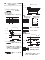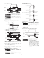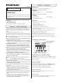
1
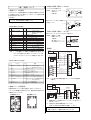
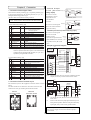
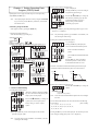
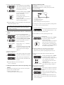
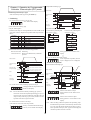
2 章 準備 HP-6136-6 取扱説明書 1. ご使用の前に付属品をお確かめください SG8030J-D DINレール取付タイプ SG8030J 本体 表面接続ソケット 1 取扱説明書 1 データメモリ型コントローラ SG8030J-D(U) SG8030J-U 埋め込み取付タイプ SG8030J 本体 裏面接続ソケット 1 取扱説明書 1 埋め込み取付用アダプタ 1 この度は当社製品をお買い求めいただきありがとうございます。 ご使用前に、この取扱説明書を良くお読みになり、正しくお使い ください。 本書は、SG8030J-D(DIN レール取付タイプ)、SG8030J-U(埋め 込み取付タイプ) 共通の取扱説明書です。本体 (SG8030J) の取り扱 いは共通です。 2. 概要 (1) 本製品は次の運転ができます。 ・位置決め運転(インデックス運転) ・ 有害物質 ・連続運転(スキャン運転) RoHS(EU 指令 2002/95/EC 27Jan.2003)適合 ・機械原点復帰運転(ホーム運転) ・1 パルス運転(ジョグ運転)* テストモードのみ 1 章 安全上のご注意 (2) 選択位置決め方式と順送り位置決め方式を切り換えることがで きます。 この製品は、一般的な産業機器の機器組み込み用として設計されて (3) 加減速パターンを直線、ジャークの 2 パターンから選択でき います。その他の用途には使用しないでください。この警告を無視 ます。 した結果生じた損害の補償については、当社は一切その責任を負い また、本製品は外部コントローラとの入力回路が電流ソース入力、 ませんので、あらかじめご了承ください。 出力回路が電流シンク出力のコントローラです。外部コントローラ 製品の取り扱いは、適切な資格を有する人が行なってください。 には、入力回路が電流ソース入力、出力回路が電流シンク出力の製 ここに示した注意事項は、製品を安全に正しくお使いいただき、 品をご使用ください。形状はコンパクトなDIN サイズに納めました。 お客様や他の人々への危害や損傷を未然に防止するためのもので す。内容をよく理解してから本文をお読みください。 3. 各部の名称 警告 この警告事項に反した取り扱いをすると、 火災や感電などにより死 ࡈࡠࡦ࠻ࡄࡀ࡞ 亡または重傷を負う場合がある内容を示しています。 SG8030J EXT PROG TEST ᄖㇱജࡕ࠼.'& ࡊࡠࠣࡓࡕ࠼.'& ࠹ࠬ࠻ࡕ࠼.'& ●爆発性雰囲気中、引火性雰囲気中では使用しないでください。 火災・けがの原因になります。 VEXTA CONTROLLER ●設置、接続、運転・操作、点検の作業は、適切な資格を有する人 ࠺࠲␜ㇱ が行なってください。火災・けがの原因になります。 ●コントローラの電源には、一次側と二次側が強化絶縁された電源 を使用してください。感電の原因になります。 SET MODE ࠶࠻ࠠ ●接続は接続図にもとづき、確実に行なってください。火災の原因 ORIENTAL MOTOR CO.,LTD. MADE IN JAPAN になります。 ࡕ࠼ࠠ ࠕ࠶ࡊࠠ ࠳࠙ࡦࠠ ●停電したときは、コントローラの電源を切ってください。停電復 旧時に接続したモーターが突然起動して、けが・装置破損の原因 4. 各モードの説明 になります。 3 つの制御モードがあり、モード (MODE) キーを 1 回押すごとに ●コントローラを分解・改造しないでください。火災の原因になり EXT → PROG → TEST と LED の点灯が切り替わります。 ます。内部の点検や修理は、お買い上げになった支店・営業所に 連絡してください。 <制御モードの種類> ・ 外部入力(EXT)モード 注意 この注意事項に反した取り扱いをすると、感電やその他の事故によ 電源を投入すると、外部入力モードが自動的に選択されます。 り傷害を負う、 または物的損害が発生する場合がある内容を示して すでに必要な運転データが書き込まれているときにプログマブル います。 コントローラなどによるモーターの運転が行なえます。 ●コントローラの仕様値を超えて使用しないでください。装置破損 運転方法は 6 ページ「6 章 プログラマブルコントローラによる の原因になります。 運転」をご覧ください。 ●コントローラは筐体内に設置してください。異物が入ったりして、 火災・装置破損の原因になります。 ・ プログラム(PROG)モード ●コントローラの周囲には、可燃物を置かないでください。火災の 運転データを設定するモードです。データ設定方法は 3 ページ 原因になります。 「4 章 運転データの設定」をご覧ください。 ●装置の故障や動作の異常が発生したときは、装置全体が安全な方 向へはたらくよう非常停止装置、または非常停止回路を外部に設 ・ テスト (TEST) モード 置してください。けがの原因になります。 手動による動作確認などを行なうときに使用するモードです。 ●異常が発生したときは、ただちに運転を停止して、コントローラ 運転方法は 5 ページ「5 章 手動による動作確認」をご覧くださ の電源を切ってください。火災・けがの原因となります。 い。 ●コントローラを廃棄するときは、できるだけ分解し、産業廃棄物と して処理してください。 1 3. 内部出力回路(電流シンク出力) 3 章 接続について ドライバへ出力する信号です。 O#એਅ 信号名: CW パルス / パルス、 1. 接続ソケット信号表 ࡇࡦ0Q ቯ㔚ᵹ CCW パルス / ޔ ࿁〝 プログラムモードで選択位置決め方式と順送り位置決め方式のどち 回転方向 らかを選択できます。切り換えについては 3 ページ「(2)位置決め運 ǡ 8 8 転方式の設定」をご覧ください。 以下の表は H レベル:端子開放のとき 外部コントローラへ出力する信号です。 +12V L レベル:端子を GND 端子と短絡したとき 信号名: ビジー O#એਅ として書かれています。 ࡇࡦ0Q Mǡ (1)選択位置決め方式の場合 ࡇࡦ ାภฬ 0Q ㆇォࡕ࠼ಾ឵ Mǡ ᣇะ 8 ᯏ⢻ ജ *ࡌ࡞ψ⟎ㆇォ .ࡌ࡞ψᯏ᪾ේὐᓳᏫㆇォ ޓޓޓޓㅪ⛯ㆇォ )0& ജ &%8ߩ)0& 㧗8 ജ &%8ജ┵ሶ ࡆࠫ ജ ࡄ࡞ࠬ⊒ᝄਛߦജ ജ ᯏ᪾ේὐࡦࠨജ *1/'.5 ࠬ࠲࠻ ജ ࠬ࠲࠻ାภ %9ࡄ࡞ࠬࡄ࡞ࠬ ജ %9ࡄ࡞ࠬࡄ࡞ࠬജ┵ሶ %%9ࡄ࡞ࠬ࿁ォᣇะ ജ %%9ࡄ࡞ࠬ࿁ォᣇะജ┵ሶ ജ *ࡌ࡞ψߔߴߡߩേࠍᱛ ᄖㇱᱛ .ࡌ࡞ψേน⢻⁁ᘒ ജ ࠬ࠹࠶ࡊ0Qㆬᛯ㨇%9ㅪ⛯ㆇォ㨉 /㨇%9ࠬࠠࡖࡦ㨉 /㨇%%9ࠬࠠࡖࡦ㨉 ജ ࠬ࠹࠶ࡊ0Qㆬᛯ㨇%%9ㅪ⛯ㆇォ㨉 4. 内部入力回路(電流ソース入力) 外部コントローラ、センサから入力される信号です。 信号名: 運転モード切換、 8 HOMELS、 スタート、 外部停止、 ࡇࡦ0Q ǡ M0[CW スキャン] 、㨮㨮ޔ 㨮㨮 M1[CCW スキャン] Mǡ 8 5. 接続例 &%8 注記:[ ]内は運転モード切換入力が通電時の時に有効となり ます。M0、M1 端子の切り換えについては 6 ページ「6 章 プログラマブルコントローラによる運転」をご覧くださ い。 㔚Ḯ 8 )0& SG8030J ┵ሶ⇟ภ ㆇォࡕ࠼ಾ឵ ᄖㇱࠦࡦ࠻ࡠ )0& 8 ࡆࠫ (2)順送り位置決め方式の場合 ࡇࡦ ାภฬ 0Q ㆇォࡕ࠼ಾ឵ 5 ᄖㇱᱛ /=%9ࠬࠠࡖࡦ? %9 2.5 %9 2.5 %%9 &+4 %%9 &+4 %%9ࡄ࡞ࠬ 㧛࿁ォᣇะ /=%%9ࠬࠠࡖࡦ? 注記: パルス出力部は定電流回路になっているので外部抵抗は 不要です。 8 )0& 8 &%8㔚Ḯ )0& 付属品の接続ソケットの端子の配列は、次のようになります。 ソケット上に端子番号の表示があります。接続は表示を確認しなが ら確実に行なってください。 6 2. 接続ソケット端子配列 7 %9ࡄ࡞ࠬ 㧛ࡄ࡞ࠬ &%8㔚Ḯ 8 *1/'.5 ᯏ⢻ ജ *ࡌ࡞ψ⟎ㆇォ .ࡌ࡞ψᯏ᪾ේὐᓳᏫㆇォ ജ &%8ߩ)0& )0& ജ &%8ജ┵ሶ 㧗8 ജ ࡄ࡞ࠬ⊒ᝄਛߦജ ࡆࠫ ജ ᯏ᪾ේὐࡦࠨജ *1/'.5 ജ ࠬ࠲࠻ାภ ࠬ࠲࠻ %9ࡄ࡞ࠬࡄ࡞ࠬ ജ %9ࡄ࡞ࠬࡄ࡞ࠬജ┵ሶ %%9ࡄ࡞ࠬ࿁ォᣇะ ജ %%9ࡄ࡞ࠬ࿁ォᣇะജ┵ሶ ജ *ࡌ࡞ψߔߴߡߩേࠍᱛ ᄖㇱᱛ .ࡌ࡞ψേน⢻⁁ᘒ %9ࠬࠠࡖࡦ ജ ജߢ%9ㅪ⛯ㆇォ %%9ࠬࠠࡖࡦ ജ ജߢ%%9ㅪ⛯ㆇォ 㕙ធ⛯䉸䉬䉾䊃 ࠬ࠲࠻ ᣇะ ࠼ࠗࡃ SG8030J ┵ሶ⇟ภ ㆇォࡕ࠼ಾ឵ ᄖㇱࠦࡦ࠻ࡠ )0& 6 7 %9ࡄ࡞ࠬ 㧛ࡄ࡞ࠬ 8 ⵣ㕙ធ⛯䉸䉬䉾䊃 5 ࠼ࠗࡃ ࡆࠫ 8 *1/'.5 %%9ࡄ࡞ࠬ 㧛࿁ォᣇะ %9 2.5 %9 2.5 %%9 &+4 %%9 &+4 4 *1 4 9 3 3 2 10 11 1 *2 9 1 11 10 機械原点センサの制御出力はノーマルオープン (NO)タイプ をお使いください。 外部停止入力信号は通電状態にしてください。 使用しない場合は必ずGND端子に接続してください。 電源入力は DC24V ± 5% 消費電流 0.1A です。 容量に余裕をもった電源の使用をおすすめします。 2 2 4 章 運転データの設定 プログラム(PROG)モード 運転データ設定はプログラムモードを選択し、フロントパネルの キー(アップ、ダウン、セット)を操作して行ないます。 注記: アップキーまたはダウンキーで設定したい数値を表示さ せた後は、必ずセットキーを押してください。セット キーを押さなかった場合は、そのデータは記憶されませ ん。 (2)位置決め運転方式の設定 「tyPE」を表示します。 セットキーを押すと、位置決め運転方 式の設定が行なえます。 SET ↓ アップキーまたはダウンキーを押し、 選択位置決め(tyP-d)か、順送り位置 決め(tyP-S)かを変更します。 出荷時設定は「選択位置決め(tyP-d) 」 です。 ・プログラムモードの選択 ●セットキーを押すと、表示されている位置決め運転方式が記 憶され「P.no-1」を表示します。 モードキーを押してプログラムモードを選択します。 <運転データを選択するには> キー操作で設定するデータ項目を選択します。 注記: 位置決め運転方式はデータの初期化を行なっても、初期 化前の状態を保持します。 ࡊࡠࠣࡓࡕ࠼ㆬᛯ MODE (3)加減速パターンの設定 ⟎࠺࠲ ࠬ࠹࠶ࡊ േࡄ࡞ࠬᢙ㨯ㆇォࡄ࡞ࠬㅦᐲ ࿁ォᣇะ 2 㧗 ⑽એ ࡄ࡞ࠬജᣇᑼ 2 SET ࠬ࠹࠶ࡊ േࡄ࡞ࠬᢙ㨯ㆇォࡄ࡞ࠬㅦᐲ ࿁ォᣇะ 2 直線加減速パターン ⟎ㆇォᣇᑼ 2 SET SET ࠬ࠹࠶ࡊ േࡄ࡞ࠬᢙ㨯ㆇォࡄ࡞ࠬㅦᐲ ࿁ォᣇะ 2 「tr」を表示します。 セットキーを押すと、現在設定されて いる加減速パターンを表示し、データ の設定が行なえます。 㧗 ⑽એ ࿁ߔ ジャーク加減速パターン ടᷫㅦࡄ࠲ࡦ㨯 ടᷫㅦ࠻ 2 セットキーを押すと、加減速パターン が記憶され、加減速レートの設定が行 なえます。 േࡄ࡞ࠬㅦᐲ 2 ●直線加減速パターンとジャーク加減速パターンは、それぞれ 下図のような加減速パターンになります。 ࠬ࠹࠶ࡊ േࡄ࡞ࠬᢙ㨯ㆇォࡄ࡞ࠬㅦᐲ ࿁ォᣇะ 2 ㅦ ᐲ 84 ᯏ᪾ේὐᓳᏫㆇォ㨯ㅪ⛯ㆇォ ㆇォࡄ࡞ࠬㅦᐲ 2 SET ㅦ ᐲ 84 85 ࿁ߔ 85 ⋥✢ടᷫㅦࡄ࠲ࡦ ᤨ㑆 ࠫࡖࠢടᷫㅦࡄ࠲ࡦ ᤨ㑆 ߪߔߴߡߩㆇォߦㅢߩ࠺࠲ߢߔޕ (4)加減速レートの設定 1. 共通データの設定 アップキーまたはダウンキーを押し、 数字を変更します。 (1)パルス出力方式の設定 SET 「PULSE」を表示します。 セットキーを押すと、現在設定されて いるパルス出力方式を表示し、設定が 行なえます。 ↓ アップキーまたはダウンキーを押し、 1 パルス方式、2 パルス方式を変更しま す。 出荷時設定は、 「2-PLS(2 パルス方 式) 」です ടᷫㅦࡄ࠲ࡦ ടᷫㅦ࠻=OUM*\? 注記: ここでは加減速パターンは切り換えられません。 加減速レートは次の28種類から設定できます。〔単位:ms/kHz〕 1, 2, 4, 5, 6, 8, 10, 12, 14, 15, 16, 18, 20, 22, 24, 25, 26, 28, 30, 35, 40, 45, 50, 60, 70, 80, 90, 100 ●セットキーを押すと、表示している値が記憶され、起動パル ス速度の設定に移ります( 「vS」を表示します) 。 ●セットキーを押すと、表示されているパルス出力方式が記憶 され、 「tyPE」を表示します。 注記: パルス出力方式はデータの初期化を行なっても、初期化 前の状態を保持します。 3 (5)起動パルス速度データの表示 「vS」を表示します。 セットキーを押すと、現在設定されて いる起動パルス速度を表示し、データ SET の設定が行なえます。 4. 位置決めデータの設定 次のような動作パターン(ステップ)を 4 ステップまで設定できま す。データの設定は動作パルス数、運転パルス速度、回転方向のみ を設定します。 ステッピングモーターの動作パターン ࡄ࡞ࠬㅦᐲ アップキーまたはダウンキーを押した ままにすると、連続して数字が変わり ます。 VT 84 㧔M*\㧕 ࠠ ࠠ 㧔*\㧕 85 出荷時設定は「1(100Hz) 」です。 100Hz単位で設定が行なえます。 設定は実際の速度の 1/100で入力しま す(100Hz は「1」と設定します) 。 ●セットキーを押すと、表示されている値が記憶され、 「Ho. vr」を表示します。 (1)機械原点復帰運転パルス速度データの表示 「Ho. vr」を表示します。 セットキーを押すと、機械原点復帰 運転パルス速度データの設定が行な SET えます。 VS tr ᤨ㑆 起動パルス速度 加減速レート VR 動作パルス数 運転パルス速度 位置決め移動量 * VS、tr は 1 種類の設定となり、4 ステップに共通のデータとな ります。 設定方法は 3、4 ページをご覧ください。 VS (起動パルス速度) をVR (運転パルス速度) より速く設定した 時は、加減速運転を行なわず VS の速度で一定速運転します。 2. 機械原点復帰運転パルス速度データの設定 േࡄ࡞ࠬᢙ (1)ステップ 1 のデータ表示 モードキーを押してプログラムモード を選択すると、 「P.no-1」を表示し “1”が点滅します。 ●セットキーを押すとステップ1の動作パルス数の設定が行なえ ます。 アップキーまたはダウンキーを押した (2)動作パルス数の設定 ままにすると数字が連続して変わりま す。 㧔%9M*\㧕 ࠠ ࠠ 㧔%%9M*\㧕 出荷時設定は「-10(開始方向 CCW1000Hz) 」です。 100Hz単位で設定が行なえます。 設定は実際の速度の 1/100で入力しま す(100Hz は「1」と設定します) 。 ࠠ ࠠ <開始方向の設定> ・CW 方向に開始 アップキーまたはダウンキーを押した ままにすると、数字が連続して変わり ます。 出荷時設定は「0(0 パルス) 」です。 1パルス単位で設定が行なえます。 「99999」でアップキーを押すと「0」 に、 「0」でダウンキーを押すと 「99999」に変わります。 ●セットキーを押すと、表示しているパルス数を記憶した後、 運転パルス速度の設定値を表示し、運転パルス速度の設定に 移ります。 一番左側の桁が「無表示」の時、CW 方 向を表わします。 ・CCW 方向に開始 一番左の桁が「-」表示の時、CCW 方 向を表わします。 ●セットキーを押すと、表示されているデータが記憶されます ( 「P.no-1」を表示します) 。 3. 連続運転パルス速度データの設定 *連続運転パルス速度は、機械原点復帰運転パルス速度で設定 した値となります。 「連続運転パルス速度」=「機械原点復帰運転パルス速度」 (3)運転パルス速度 VR、回転方向の設定 アップキーまたはダウンキーを押し たままにすると、数字が連続して変わ ります。 㧔%9㧦M*\㧕 出荷時設定は「10(CW:1000Hz) 」で ࠠ す。100Hz 単位で設定が行なえます。 設定は実際の速度の 1/100で入力し ࠠ ます(100Hz は「1」と設定します) 。 㧔%%9㧦M*\㧕 <回転方向の設定> ・CW 方向に設定 一番左側の桁が「無表示」の時、CW 方 向を表わします。 ・CCW 方向に設定 一番左側の桁が「-」表示の時、CCW 方向を表わします。 ●セットキーを押すと、表示している値が記憶されステップ 2 の 位置決めデータ設定になります(「P.no-2」を表示します) 。 4 (4)ステップ 2 以降のデータ設定 設定方法は「P.no-1」と同様です。 ステップ2以降は必要なステップ数に 応じて(1)∼(3)の操作を繰り返し ます。 例) 位置決めデータを設定しない場合 データ設定を行なわないステップは、 動作パルス数を「0」に設定してくださ い。 5. 初期化の方法 5 章 手動による動作確認 テスト(TEST)モード 手動による動作確認は、テストモードを選択し、フロントパネルの キーを操作して行ないます。テストモードでは、プログラムモード で設定した連続運転、機械原点復帰運転、位置決め運転のデータに 従って運転します(ドライバやセンサとの結線確認の時などにも便 利です) 。 1. 運転の選択 アップキー、ダウンキーにより運転を選択します。 セットキーを押した状態で電源を投入すると、設定したデータが消 去され、パルス出力方式と位置決め運転方式を除き出荷時の運転 データに再設定 (初期化)されます。 ࠹ࠬ࠻ࡕ࠼ㆬᛯ MODE ᯏ᪾ේὐᓳᏫㆇォ 初期データ ࠺࠲⸳ቯ㗄⋡ ࠺࠲␜ ⸳ቯ୯ േࡄ࡞ࠬᢙ ࡄ࡞ࠬ ㆇォࡄ࡞ࠬㅦᐲ㧔84㧕 *\ ᯏ᪾ේὐᓳᏫㆇォ㐿ᆎᣇะ 㧙 %%9ᣇะ ᯏ᪾ේὐᓳᏫㆇォࡄ࡞ࠬㅦᐲ *\ ടᷫㅦ࠻㧔VT㧕 OUM*\ േࡄ࡞ࠬㅦᐲ㧔85㧕 *\ ㅪ⛯ㆇォࡄ࡞ࠬㅦᐲ ᯏ᪾ේὐᓳᏫㆇォㅦᐲߣหߓߢߔ ೋᦼൻ೨ߩ⁁ᘒࠍᜬߒ߹ߔ ࡄ࡞ࠬജᣇᑼ 㧔⩄ᤨߪࡄ࡞ࠬᣇᑼ㧕 ೋᦼൻ೨ߩ⁁ᘒࠍᜬߒ߹ߔ ⟎ㆇォᣇᑼ 㧔⩄ᤨߪㆬᛯ⟎ᣇᑼ㧕 ࠫࡖࠢ ടᷫㅦࡄ࠲ࡦ VT ടᷫㅦࡄ࠲ࡦ ⟎ㆇォ ࡊ࠶࠹ࠬޓޓޓ ⟎ㆇォ ࡊ࠶࠹ࠬޓޓޓ ⟎ㆇォ ࡊ࠶࠹ࠬޓޓޓ ⟎ㆇォ ࡊ࠶࠹ࠬޓޓޓ %%9ㅪ⛯ㆇォ 6. データ書き込みエラー 「d-Err」とは・・・ 正常にデータが書き込まれていないと きに表示します。 初期化を行なった後、再度プログラム データを書き込んでください。 初期化については 5 ページ「5. 初期化の方法」をご覧ください。 %9ㅪ⛯ㆇォ 2. 運転開始方法 位置決め運転、機械原点復帰運転 →セットキーを押すと運転を開始します。 連続運転、1 パルス運転 →セットキーを1秒以上押すと運転を開始します。 →セットキーを 1 秒以内に離すと、1 パルスだけ出力します。 ●運転中は表示が点滅します。 注記: 順送り位置決め方式になっている場合でも、TEST モード の位置決め運転では、運転終了後も、そのステップを表 示します。 5 6 章 プログラマブルコントローラによる運転 外部入力(EXT)モード (2)順送り位置決め方式の場合 ࡕ࠲ߩേ߈ ・外部入力モードの選択 モードキーを押して外部入力モードを選択します。 OUએ ㆇォࡕ࠼ಾ឵ OUએ߹ߚߪࡆࠫ߇.ࡌ࡞ߦߥࠆ߹ߢ 1. 位置決め運転 ࠬ࠲࠻ 例) 全ステップにデータが設定されていない場合 「no-d」表示が点滅します。 OUએౝ %9ࡄ࡞ࠬ %%9ࡄ࡞ࠬ (1)選択位置決め方式の場合 <ステップ No. 選択信号> OUએౝ OUએౝ ステップ No. 選択信号 M0[CW スキャン]と M1[CCW スキャン (10、11 ピン)は運転モード切換入力により、下記のように機能 が変わります。 ㆇォࡕ࠼ ಾ឵ * * * * . . . OUએ ࡆࠫ / / * . * . * . * * * . . * * . േ <運転例> ・ 位置決めデータが 2 ステッ プ入力されている場合 ・ 位置決めデータが 4 ステッ プ入力されている場合 ࿁⋡ࠬ࠲࠻ ࿁⋡ࠬ࠲࠻ ࠬ࠹࠶ࡊㆬᛯ ࠬ࠹࠶ࡊㆬᛯ ࠬ࠹࠶ࡊㆬᛯ ࠬ࠹࠶ࡊㆬᛯ ᯏ᪾ේὐᓳᏫㆇォታⴕ %9ㅪ⛯ㆇォታⴕ %%9ㅪ⛯ㆇォታⴕ ⟎࠺࠲ ⟎࠺࠲ ࿁⋡ࠬ࠲࠻ ࿁⋡ࠬ࠲࠻ ⟎࠺࠲ ⟎࠺࠲ ࿁⋡ࠬ࠲࠻ ⟎࠺࠲ ࿁⋡ࠬ࠲࠻ ࿁⋡ࠬ࠲࠻ 運転モード切換は次のようになります。 H レベル(非通電時): 位置決め運転選択 L レベル(通電時) : 機械原点復帰運転、連続運転選択 ⟎࠺࠲ ࿁⋡ࠬ࠲࠻ 運転中は「no-1」表示が点滅します。 ↓ 例)ステップ 2 のデータが入力されている場合 運転終了後、次のステップ 2 を表示し ます( 「no-2」を表示します) 。 ࡕ࠲ߩേ߈ OUએ ㆇォࡕ࠼ಾ឵ OUએ OUએ /㨇%9ࠬࠠࡖࡦ㨉 /㨇%%9ࠬࠠࡖࡦ㨉 2. 連続運転 (1)選択位置決め方式の場合 OUએ OUએ߹ߚߪࡆࠫ߇.ࡌ࡞ߦߥࠆ߹ߢ ࠬ࠲࠻ ࡕ࠲ߩേ߈ OUએౝ OUએ ࡆࠫ ㆇォࡕ࠼ಾ឵ %9ࡄ࡞ࠬ %%9ࡄ࡞ࠬ OUએౝ OUએౝ OUએ /㨇%9ࠬࠠࡖࡦ㨉 /㨇%%9ࠬࠠࡖࡦ㨉 例) ステップ 4の位置決め運転中の場合 運転中は「no-4」表示が点滅します。 OUએ߹ߚߪࡆࠫ߇.ࡌ࡞ߦߥࠆ߹ߢ OUએ OUએౝ OUએౝ OUએ ࡆࠫ %9ࡄ࡞ࠬ %%9ࡄ࡞ࠬ OUએౝ 注記: 必ず選択位置決め方式「tyP-d」になっていることを確 認してください。順送り位置決め方式「tyP-S」になって いるときは、運転モード切換(1 ピン)の ON/OFF にかかわ らず、M0[CW スキャン](10 ピン)または M1[CCW スキャン] (11 ピン)が ON になると、連続運転を開始します。 OUએౝ CW方向の運転パルスを出力します。 運転中は「ScAn」表示が点滅します。 CCW方向の運転パルスを出力します。 運転中は「-ScAn」表示が点滅します。 例) ステップ1にデータが設定されていない場合 (選択されたステップにデータが設定されていないとき) データが設定されていないステップ1 を選択すると「no-d1」表示が点滅し ます。 注記: 位置決め運転後に連続運転を行なう際には、必ず M0、M1 信号を一度 H レベルに戻してから L レベルにしてくださ い。運転モード切換前に M0、M1 信号を L レベルにした場 合は、 「Ho. 」を表示し連続運転を行ないません。 6 原点復帰運転パターン (1)ワークが HOMELS 上にないとき (2)順送り位置決め方式の場合 *1/'.5 ࡕ࠲ߩേ߈ *QXTߩ⸳ቯ߇ %9ᣇะߩߣ߈ *QXT %9 85 85 OUએౝ %9ࠬࠠࡖࡦ %%9ࠬࠠࡖࡦ 85 %%9 OUએౝ OUએ *1/'.5 ࡆࠫ %9 *QXTߩ⸳ቯ߇ %%9ᣇะߩߣ߈ %9ࡄ࡞ࠬ %%9ࡄ࡞ࠬ OUએౝ OUએౝ 85 (2)ワークが HOMELS 上にあるとき CW方向の運転パルスを出力します。 運転中は「ScAn」表示が点滅します。 *QXTߩ⸳ቯ߇ %9ᣇะߩߣ߈ *QXTߩ⸳ቯ߇ %%9ᣇะߩߣ߈ *1/'.5 <エラーメッセージ> 「Ho.Err」とは・・・ 㧔㧕 85 85 85 %9 85 %%9 㧔㧕 85 ࡕ࠲ߩേ߈ *QXT *1/'.5 3. 機械原点復帰運転 %9 *1/'.5 85 %9 %%9 CCW方向の運転パルスを出力します。 運転中は「-ScAn」表示が点滅します。 選択位置決め運転方式、順送り位置決め運転方式共通です。 (運転開始方向・・・CCW 方向の場合) 85 %%9 㧔㧕 85 機械原点復帰運転時に、機械原点センサ がチャタリングや振動等で正常に検出さ れなかった場合に表示されます。センサ が正常に検出できるように調整してくだ さい。 4. 外部停止入力時 84 㧔㧕 %%9 選択位置決め運転方式、順送り位置決め運転方式共通です。 *1 HOMELS を検出してから10ms以内で減速を開始します。 *2 HOMELSを脱出していなくても反転します。 ࡕ࠲ߩേ߈ OUએ ㆇォࡕ࠼ಾ឵ ࠬ࠲࠻ 㧔㧕 ࠬ࠲࠻ OUએ OUએ߹ߚߪࡆࠫ߇.ࡌ࡞ߦߥࠆ߹ߢ OUએ ᄖㇱᱛ OUએ 㧔㧕 *1/'.5 OUએౝ 㧔㧕 㧔㧕 ࡆࠫ OUએ OUએౝ OUએ %9ࡄ࡞ࠬ %%9ࡄ࡞ࠬ ࡆࠫ OUએౝ %9ࡄ࡞ࠬ %%9ࡄ࡞ࠬ OUએౝ 外部停止信号入力時に表示します。 通電状態になっていない場合、 「E.StoP」表示が点滅します。 この表示が出たときは、外部停止信号 以外の信号からの入力を受け付けませ ん。 解除するには外部停止信号とGNDを短 絡してください(接続については 2 ページ「3 章 接続について」をご覧 ください) 。 OUએౝ (1)運転モード切換後、スタート信号が入力されるとモーターは CCW方向へ運転を開始します。 ↓ (2)HOMELS(機械原点センサ)を検出すると減速後、反転し、CW 方向へ VSの速度で運転を行ないます。 ↓ (3)HOMELS を一旦脱出してから再度反転し、CCW 方向へ VS の速度 で運転を行ないます。 ↓ (4)再び HOMELS を検出するとモーターが停止します。 運転中は「Ho. 」表示が点滅します。 ↓ (5)機械原点復帰すると、運転を終了します。 機械原点に復帰すると「Ho.End」を表 示します。 7 7 章 メッセージ一覧 PQ PQF PQF 2PQ 27.5' 2.5 5%#P 5%#P V5%P V5%P V*Q VPQ VT VT V[2' V[2F V[25 X5 ౝኈ ᄖㇱᱛਛ ࠺࠲ᦠ߈ㄟߺࠛ ᯏ᪾ේὐᓳᏫㆇォ ᯏ᪾ේὐᬌࠛ ᯏ᪾ේὐᓳᏫㆇォ⚳ੌ ᯏ᪾ේὐᓳᏫㆇォ ㅪ⛯ㆇォߩㆇォࡄ࡞ࠬㅦᐲ ⸳ቯ ⟎ㆇォ ߔߴߡߩ⟎ㆇォ࠺࠲ ߥߒ ㆬᛯߒߚࠬ࠹࠶ࡊߦ ⟎ㆇォ࠺࠲ߥߒ ⟎࠺࠲⸳ቯ ࡄ࡞ࠬജᣇᑼ⸳ቯ ㅪ⛯ㆇォ %9ᣇะ ㅪ⛯ㆇォ %%9ᣇะ ࠹ࠬ࠻ࡕ࠼ ㅪ⛯ㆇォ %9ᣇะ ࠹ࠬ࠻ࡕ࠼ ㅪ⛯ㆇォ %%9ᣇะ ࠹ࠬ࠻ࡕ࠼ᯏ᪾ේὐᓳᏫㆇォ ࠹ࠬ࠻ࡕ࠼⟎ㆇォ ടᷫㅦࡄ࠲ࡦ㨯࠻⸳ቯ ടᷫㅦࡄ࠲ࡦ⸳ቯ ടᷫㅦ࠻⸳ቯ ⟎ㆇォᣇᑼ⸳ቯ ⟎ㆇォᣇᑼㆬᛯ ឝタࡍࠫ 2㧦ᄖㇱᱛജᤨ 2㧦࠺࠲ᦠ߈ㄟߺࠛ 2㧦ᯏ᪾ේὐᓳᏫㆇォ 2㧦ᯏ᪾ේὐᓳᏫㆇォ ࡄ࡞ࠬㅦᐲ࠺࠲ߩ⸳ቯㅪ ⛯ㆇォࡄ࡞ࠬㅦᐲ࠺࠲ߩ⸳ቯ 2㧦⟎ㆇォ 45 +0.5 0 ࡔ࠶ࠫ '5VQ2 F'TT *Q *Q'TT *Q'PF *QXT 取付穴加工寸法 45 +0.5 0 2. 主な仕様 SG8030J-D(U) 2㧦 ⟎࠺࠲ߩ⸳ቯ 2㧦 ࡄ࡞ࠬജᣇᑼߩ⸳ቯ 2㧦ㅪ⛯ㆇォ ⟎࠺࠲ ࠬ࠹࠶ࡊ''ޕ2㧙41/ᦠ߈ㄟߺ ⟎ᓮ ࠗࡦࠢࡔࡦ࠲࡞ 2QKPVVQ2QKPVᣇᑼ ࠺࠲ㆬᛯାภߦࠃࠅ࠺࠲ㆬᛯ࠻࠲ࠬޔାภߦࠃࠅ ㆇォታⴕ ࠬ࠹࠶ࡊߚࠅ㨪ࡄ࡞ࠬ ㆇォࡄ࡞ࠬㅦᐲޓ㨪*\ *\න േࡄ࡞ࠬㅦᐲޓ㨪*\ *\න ടᷫㅦ࠻ޓޓ㨪OUM*\ ᓮࡕ࠼ ᄖㇱജࡕ࠼ ':6 ࡊࡠࠣࡓࡕ࠼ 241) ࠹ࠬ࠻ࡕ࠼ 6'56 ㆇォࡕ࠼ ⟎ㆇォ ࠗࡦ࠺࠶ࠢࠬㆇォ ᯏ᪾ේὐᓳᏫㆇォ ࡎࡓㆇォ ㅪ⛯ㆇォ ࠬࠠࡖࡦㆇォ 㧝ࡄ࡞ࠬㆇォ ࡚ࠫࠣㆇォ࠹ࠬ࠻ࡕ࠼ߩߺ 2㧦ㆇォߩㆬᛯ 2㧦 ടᷫㅦࡄ࠲ࡦߩ⸳ቯ ടᷫㅦ࠻ߩ⸳ቯ 2㧦 ⟎ㆇォᣇᑼߩ ⸳ቯ േࡄ࡞ࠬㅦᐲ⸳ቯ 2㧦 േࡄ࡞ࠬㅦᐲ࠺࠲ߩ␜ ߩࡔ࠶ࠫߪ৻ߢߔޕᢙሼߩㇱಽߪᄌൻߒ߹ߔޕ ᯏ᪾ේὐᓳᏫᯏ⢻ ᯏ᪾ේὐߒߩᬌ࿁ォᣇะࠍᜰቯߒ*1/'.5ߦࠃࠅ ේὐᬌ 8 章 外形図、主な仕様 ജାภ &%8ࡈࠜ࠻ࠞࡊ⚿วജᛶ᛫Mǡ㔚ᵹ࠰ࠬജ ജାภ ࡈࠜ࠻ࠞࡊ⚿วޓ020࠻ࡦࠫࠬ࠲ജޓ &%8ޓO#એਅޓ㔚ᵹࠪࡦࠢജ 㔚Ḯജ &%8r㧑ޓᶖ⾌㔚ᵹ# ⾰㊂ MI ↪࿐᷷ᐲ 㨪͠ ↪࿐Ḩᐲ 㨪㧑 ⚿㔺ߒߥߎߣ 1. 外形図(単位:mm) 97.6 5.5 77.5 0.7 48 غ44.5 48 • この取扱説明書の一部または全部を無断で転載、複製すること は、禁止されています。 • 取扱説明書に記載されている情報、回路、機器、および装置の 利用に関して産業財産権上の問題が生じても、当社は一切の責 任を負いません。 • 製品の性能、仕様および外観は改良のため予告なく変更するこ とがありますのでご了承ください。 • 取扱説明書には正確な情報を記載するよう努めていますが、万 一ご不審な点や誤り、記載もれなどにお気づきの点がありまし たら、最寄りのお客様ご相談センターまでご連絡ください。 • は、オリエンタルモーター株式会社の商標で す。 83.7 max SG8030J-D 11×M3.5 ࡞ࡈࠕ࠶ࡊߨߓ 㕙ធ⛯࠰ࠤ࠶࠻ 7.8 70 max. DIN࡞ 4 Copyright ORIENTAL MOTOR CO., LTD. 2007 50 max. 118 max. SG8030J-U http://www.orientalmotor.co.jp/ ࡄࡀ࡞ෘߺ▸࿐㧔1㨪4mm㧕 䃂㩷ຠ䈮䈧䈇䈩䈱䈗⾰䇮䈗⋧⺣䈲䈍ቴ᭽䈗⋧⺣䉶䊮䉺䊷䈻䈍䈇ว䉒䈞䈒䈣䈘䈇䇯 㩷 䊐䊥䊷䉮䊷䊦䋨ήᢱ䋩䈪䈜䇯៤Ꮺ㔚䊶PHS䈎䉌䉅䈗↪䈏น⢻䈪䈜䇯 ၒㄟߺขઃ↪ࠕ࠳ࡊ࠲ ⵣ㕙ធ⛯࠰ࠤ࠶࠻ 㩷 ฃઃᤨ㑆㩷 ᐔᣣ㩷 㩷 㩷 ᦐᣣ㩷 ᧲㩷 ੩㩷 TEL 0120-925-410 ฬฎደ㩷 TEL 0120-925-420 ᄢ㩷 㒋㩷 TEL 0120-925-430 48 58 5.5 9:00䌾18:30 9:00䌾17:30 106 max. FAX 0120-925-601 FAX 0120-925-602 FAX 0120-925-603 䈖䈱ขᛒ⺑ᦠ䈲ౣ↢⚕䉕↪䈚䈩䈇䉁䈜䇯 8 Chapter 2 Preparation HP-6136-6 1. Before Use Operating Manual Check to make sure that all parts are included before use. SG8030J-D DIN Rail Mounting Model SG8030J Unit Flush Connection Socket 1 Operating Manual Data Memory Type Controller SG8030J-D(U) SG8030J-U Recessed Mounting Model SG8030J Unit Connection Socket 1 Operating Manual Recessed Mounting Adapter 1 Thank you for purchasing an Oriental Motor product. To obtain the best performance from your equipment, please read this manual thoroughly before use. This manual is common in SG8030J-D (DIN rail mounting model), SG8030J-U (recessed mounting model). The operation of the main body (SG8030J) is common. 1 1 2. Overview (1) This product can be operated as follows. • Positioning (index) RoHS (Directive 2002/95/EC 27Jan.2003) compliant • Continuous operation (scan) • Return to mechanical home (home) Chapter 1 Safety Precautions • Signal pulse (jog) ∗Used only in test mode (2) The positioning type can be either data selection positioning type or This product is designed to be incorporated into general industrial sequential positioning type. machinery, and must not be used for other purposes. It should be noted (3) The acceleration/deceleration pattern can be selected from two that we are not responsible for any damages caused by ignoring this warning. patterns, which are linear and jerk control. Only qualified personnel should handle the product. The controller comes in a compact DIN size. The cautions described below are intended to ensure correct use of the In this product, the input circuit with an external controller is current product and to prevent the customer and other people from being injured. source type input, and the output circuit is current sink type output. Warning If this Warning is ignored, death or serious injury may be caused Use the external controller of current source type input, current sink type output. by fire or electric shock. z Do not use the product in an explosive or flammable atmosphere. Otherwise, fire and injury may occur. 3. Explanation of Control Panel z Qualified installers should be assigned to the work of installation, External input mode indicator Front panel connection, running, operation and inspection. This is intended Program mode indicator Test mode indicator to prevent fire and injury. SG8030J EXT PROG TEST z The controller power supply to be used should be a DC power supply where the primary and secondary sides are provided VEXTA CONTROLLER Data display with reinforced insulation. Otherwise, electric shock may occur. z Electrical connections must be made in strict accordance with the connection diagram. Otherwise, fire may occur. z Turn off controller power in the event of power interruption. SET MODE SET key When the power is restored, the motor may start up suddenly ORIENTAL MOTOR CO.,LTD. MADE IN JAPAN and cause injuries or damage to the equipment. MODE key UP key DOWN key z Do not disassemble, or modify the controller. Otherwise, fire may occur. When internal inspection or repair must be made, 4. Explanation of the Controller's Modes contact your local sales office. The SG8030J has three control modes. Pressing the MODE key causes Caution If this Caution is ignored, injury or physical damage may be the mode to change, from external to program to test mode, as indicated caused by electric shock or other accidents. by the mode indicators. z Do not use the controller in excess of its ratings. Otherwise, the equipment may be damaged. < The three Control Modes > z Install the controller inside a cabinet. Otherwise, fire may occur • External (EXT) Mode or the equipment may be damaged. This mode is automatically selected when the SG8030J is turned on. z Do not place combustibles around the controller. Otherwise, fire When the required operating data has already been recorded, motor may occur. operation is controlled by a programmable controller. z Provide an emergency-stop device or emergency-stop circuit See p.14 “Ch.6 Operation by Programmable Controller”. external to the equipment so that the entire equipment will • Hazardous substances operate safely in the event of a system failure or malfunction. Failure to do so may result in injury. z Immediately when trouble has occurred, stop running and turn off the controller power. Failure to do so may result in fire or injury. z To dispose of the controler, disassemble it into parts and components as much as possible and dispose of individual parts/components as industrial waste. • Program (PROG) Mode This mode is used to set operating parameters. See p.11 “Ch.4 Setting Operating Data”. • Test (TEST) Mode This mode is used for manual checks of operation and the like. See p.13 “Ch.5 Confirmation of Operation Manually”. 9 Chapter 3 Connection 3. Internal Output C i r c u i t ( C u r r e n t Pin Nos.7, 8 sinking output) 1. Connection Socket Signal Table Select the data selection positioning type or sequential positioning type by the program mode function. For switching the mode, see p.11, “(2) Setting the Positioning Operation Type”. The below tables are mentioned assuming as follows. H level : When terminal is open. L level : When terminal is short-circuited to the GND terminal. This circuit is used for signals output to a driver. Signal names: CW pulse/Rotation direction. (1) Data Selection Positioning Type Pin Signal name no. 1 Operation mode input 2 3 4 5 6 7 8 Direction Input 9 GND Input Input +24V Busy Output HOMELS Input Input Start CW pulse/Pulse Output CCW pulse Output /Rotation direction External stop Input 10 11 M0 (CW scan) M1 (CCW scan) Input Input H levelψPositioning L levelψReturn to mechanical home, Continuous operation 24VDC ground 24VDC input terminal Output during pulse generation Mechanical home sensor input Start signal CW pulse/Pulse output terminal CCW pulse/Rotation direction output terminal H levelψStops all operation L levelψRestores ready-for-operation status Step No. select (CW continuous operation) Step No. select (CCW continuous operation) 10 11 CW scan CCW scan Input Input Output Input Input Output Output Input Input Input +12V 25mA or less Pin No.4 10kΩ 10kΩ 0V +24V 680Ω 4.7kΩ 0V 5. Sample Connection Diagram +24 V 24VDC power supply SG8030J Terminal No. GND Operation mode input GND External controller Driver +24V ∗1 Function CW (PLS) CW pulse /pulse Busy Direction 0V pulse/Pulse, CCW This circuit is used for signals input from an external controller or sensor. Pin Nos. Signal names: Operation mode 1, 5, 6, input, HOMELS, start, external 9, 10, 11 2 stop, M0 (CW scan), M1 (CCW scan). (2) Sequential Positioning Type Input 120Ω 4. Internal Input Circuit (Current sourcing input) Note: The operating modes given in the parentheses are activated when the operation mode select input is on. For information on switching between the M0 and M1 terminals, see p.14 “Ch.6 Operation by Programmable Controller”. Pin Signal name no. 1 Operation mode input 2 GND 3 +24V 4 Busy 5 HOMELS 6 Start 7 CW pulse/Pulse 8 CCW pulse /Rotation direction 9 External stop constant current circuit 0V This circuit is used for signals output to an external controller. Signal name: Busy Function 12mA or less HOMELS CW (PLS) Start CCW (DIR.) H levelψPositioning L levelψReturn to mechanical home 24VDC ground 24VDC input terminal Output during pulse generation Mechanical home sensor input Start signal CW pulse/Pulse output terminal CCW pulse/Rotation direction output terminal H levelψStops all operation L levelψRestores ready-for-operation status Continuous CW operation when input Continuous CCW operation when input CCW (DIR.) CCW pulse /Rotation direction External stop ∗2 M0 (CW scan) M1 (CCW scan) Note: External resistance does not need to be installed on the pulse outputs, because they contain constant current circuits. 5VDC power supply 2. Connection Socket Terminal Layout The terminal layout on the supplied connection socket is shown below. Terminal numbers are marked on the socket. Connect each terminal correctly by checking the terminal number. +5 V GND +24 V 24VDC power supply SG8030J Terminal No. GND Operation mode input External controller GND Driver CW pulse /pulse +24V Surface connection socket 8 7 6 5 Backside connection socket 5 6 7 Busy ∗1 4 3 ∗2 3 2 10 11 1 9 1 CW (PLS) CCW (DIR.) CCW (DIR.) 8 4 9 HOMELS CCW pulse /Rotation direction CW (PLS) 11 10 2 Use normal open (NO) limit for control of the mechanical home sensor. Power for the external stop input signal must always be on during normal operation. When not using the external stop input signal, always connect to the ground terminal. Use power input of 24VDC ±5%, consumption current of 0.1A. Use of a power supply with more than sufficient capacity is recommended. 10 (2) Setting the Positioning Operation Type “tyPE” is displayed. Pressing the SET key causes the setting of the positioning operation type. SET Chapter 4 Setting Operating Data Program (PROG) Mode Operating data is set in program mode using the control panel keys (UP, DOWN, and SET keys) Press the UP or DOWN key to change the data selection positioning type (tyP-d) or sequential positioning type (tyP-s). Factory setting is “data selection positioning type”(tyP-d). Note: After displaying the numerical value by using the UP/DOWN keys, be sure to press the SET key. Otherwise, no numerical data will be saved. • Selecting Program Mode z Pressing the SET key, then the positioning operation type is saved and “P.no-1” is displayed. Select program mode by pressing the MODE key. < Selecting Operating Parameters > Select the data setting by operating keys. Note: The positioning operation type will hold its set condition, even after clearing the data settings. Selecting Program Mode MODE (3) Setting the acceleration/deceleration pattern “tr” is displayed. Pressing the SET key will display the current acceleration/deceleration pattern. SET Positioning data Step 1 Number of operating pulses. Operating pulse speed (P.12,13) at least Pulse output system∗ (P.11) one second + linear acceleration/deceleration pattern Positioning operation type∗ (P.11) Step 2 Number of operating pulses.Operating pulse speed (P.12,13) SET jerk controlled acceleration/deceleration pattern Press the SET key, then acceleration/ deceleration pattern is saved, then the acceleration/deceleration rate is set. Press twice Acceleration/deceleration pattern. Acceleration/deceleration rate at least ∗ (P.11) one second SET + Step 3 Number of operating pulses. Operating pulse speed (P.12,13) z The linear controlled acceleration/deceleration pattern and the jerk controlled acceleration/deceleration pattern are as shown below. Starting pulse speed∗ (P.12) Step 4 Number of operating pulses. Operating pulse speed (P.12,13) Return to mechanical home. Continuous operating Operating pulse speed (P.12) Speed Speed VR VR VS SET Press twice Time the jerk controlled acceleration/deceleration pattern (4) Setting the acceleration/deceleration rate Press the UP or DOWN key to change the number. The data which has ∗ marking is common for all operating. 1. Common Data Setting (1) Setting Pulse Output System “PULSE” is displayed. Pressing the SET key causes the current setting for the pulse output system to be displayed. SET acceleration /deceleration pattern acceleration /deceleration rate [ms/kHz] Note: Screen the acceleration/deceleration pattern can not be changed from this. Press the UP or DOWN key to change the 1-pulse system or the 2-pulse system. Factory setting is “2-PLS” (2-pulse system). z Pressing the SET key sets the value displayed. The unit then proceeds to display “tyPE”. VS the linear controlled Time acceleration/deceleration pattern The acceleration/deceleration rate can be selected from the following 28 rates below: [unit: ms/kHz] 1, 2, 4, 5, 6, 8, 10, 12, 14, 15, 16, 18, 20, 22, 24, 25, 26, 28, 30, 35, 40, 45, 50, 60, 70, 80, 90, 100 z Pressing the SET key sets the value displayed. The unit then proceeds to the setting of starting pulse speed (“VS” is displayed.) Note: The pulse output system will hold its set condition, even after clearing the data settings. 11 (5) Display of Starting Pulse Speed Data “VS” is displayed. Pressing the SET key causes the current setting for the starting pulse speed to be displayed. At this point a SET new data setting can be made. 100 (10kHz) key key 1 (100Hz) 4. Setting Positioning Data The SG8030J can be set for up to 4 operating patterns. Set the positioning feed distance, operation pulses speed, and the direction of the rotation. Stepping motor operating pattern Pulse speed Pressing and holding the UP or DOWN key causes the number to increase or decrease consecutively. Factory setting is 100Hz. The starting pulse speed can be set in increments of 100Hz. Settings are input at 1/100 of actual speed. Thus, the setting for 100Hz is 1. Number of operating pulses VR tr VS VS: Starting pulse speed Time tr: acceleration/deceleration rate VR: Operating pulse speed Number of operating pulses: Positioning feed distance z Pressing the SET key sets the value displayed. The following data setting is then displayed: “Ho.vr” ∗ The settings for VS and tr are the same for all four operating patterns. See p.11 and p.12 for the setting instructions. If VS (starting pulse speed) is set higher than VR (operating pulse speed), the motor operates uniformly at the VS speed, without accelerating or decelerating. 2. Setting Pulse Speed Data for Return to Mechanical (1) Data Display during Step 1 After program mode has been selected, “P. no-1” will be displayed and the “1” will flash on and off. Home z Press the SET key to set the positioning data for Step 1. (1) Display of Pulse Speed Data for Return to Mechanical Home “Ho. vr” will be displayed. Once the SET key is pressed, the pulse speed data for return to mechanical home can be set. SET Pressing and holding the UP or DOWN key causes the number to increase or decrease consecutively. (2) Setting the Number of Operating Pulses Pressing and holding the UP or DOWN key causes the number to increase or decrease consecutively. Factory setting is 0 pulses. The number of pulses can be set in increments of one. MG[ Pressing the UP key at 99999 brings the MG[ setting back to 0; pressing the DOWN key at 0 takes the setting to 99999. Factory setting is -10 ; i.e. 1000Hz in CCW direction. 0 The operation speed can be set in 100Hz key increments. The setting is input at 1/100 -2000 (CCW:200kHz) of actual speed. Thus, the setting for 100Hz is 1. < Setting the Starting Direction > • Starting in CW Direction When nothing is displayed in the furthest left position, this indicates CW direction. • Starting in CCW Direction When a minus sign is displayed in the furthest left position, this indicates CCW direction. 2000 (CW:200kHz) key z Pressing the SET key sets the number of pulses displayed. Following this, the setting for the operating pulse speed is displayed, at which point the operating pulse speed can be set. z Pressing the SET key sets the value displayed. (“P. no-1” is displayed.) 3. Setting the Data of the Continuous Operating Pulse Speed ∗ The continuous operating pulse speed is the value set for the pulse speed for return to mechanical home. Continuous operating pulse speed = Pulse Speed for return to mechanical home (3) Setting the Operating Pulse Speed (VR) and the Direction of Rotation Pressing and holding the UP or DOWN key causes the number to increase or decrease consecutively. (Factory setting is ޓ2000 (CW:200kHz) 10; i.e. 1000Hz in CW direction.) key The operating pulse speed can be set in 0 100Hz increments. key The settings are input at 1/100 of actual -2000 (CCW200kHz) speed. Thus, the setting for 100Hz is 1. < Setting the Direction of Rotation > • Setting Rotation in CW Direction When nothing is displayed in the furthest left position, this indicates CW direction. • Setting Rotation in CCW Direction When a minus sign is displayed in the furthest left position, this indicates CCW direction. z Pressing the SET key sets the value displayed and advances the setting operation to the second step setting of the positioning data. (“P. no-2” is displayed.) 12 (4) Data Settings for the Second and Subsequent Steps Setting procedures for the second and subsequent steps are the same as those for the first step. Procedures (1) to (3) are repeated for the second step and beyond as required. Chapter 5 Confirmation of Operation Manually TEST (TEST) MODE Operation can be confirmed manually by using the control panel keys (UP, DOWN, and SET keys) in test mode. In the test mode, the motor executes continuous operation, return to Ex.) When no setting is to be made for the positioning data : mechanical home and positioning according to the data set in the For steps where data settings are not going program mode. (The test mode can also be used to check driver and to be made, set the number of operating sensor connections.) pulses to 0. 5. Resetting 1. Selecting Operation Turning on power while pressing the SET key erases data settings and resets the factory settings except the pulse output system and positioning operation type. The operating mode is selected using the UP and DOWN keys. Test mode selection MODE Factory Setting Return to mechanical home Data setting item Data display Value 0 Number of operating pulses 0 pulse 10 Operating pulse speed (VR) 1000Hz Starting direction for return to CCW direction mechanical home Operating speed for return to 1000Hz 10 mechanical home Acceleration/deceleration rate 15ms/kHz 15 (tr) Starting pulse speed (VS) 100Hz 1 Continuous operating speed Same as speed for return to mechanical home Does not effect. (Factory setting is 2-pulse Pulse output system system.) Does not effect. (Factory setting is data selection Positioning operation type positioning type.) Acceleration/deceleration jerk controlled acceleration/ tr-2 pattern deceleration pattern Positioning Step. 4 Positioning Step. 3 Positioning Step. 2 Positioning Step. 1 CCW continuous oepration 6. Error when data has not been recorded correctly “d-Err” message · · · The “d-Err” message is displayed when data has not been recorded correctly. After resetting, record the program data again. See p.13 “5. Resetting” for resetting. CW continuous operation 2. Starting Operation Positioning operation, Return to Mechanical Home Press the SET key, operation is started. Continuous operation, 1 pulse operation Press the SET key, for at least one second, operation is started. Briefly (in less than one second) press and release the SET key. One pulse will be output. z During operation, message flashes on the display. Note: Even when the sequential positioning type is selected, at the TEST mode of the positioning operation, the positioning step is displayed at the completion of operation. 13 (2) Sequential Positioning Type Chapter 6 Operation by Programmable Controller External input (EXT) mode Motor rotation z Selecting External Input Type 5ms or more Select external input mode by pressing the MODE key. Operation mode input 1. Positioning 10ms or more or until busy signal at L level Start 5ms or more 10ms or less Ex.) When data has not been set for any step: “no-d” flashes on the display. Busy CW pulse CCW pulse 20ms or less 2ms or less (1) Data Selection Positioning Type < Step No. Select Signal > < Operation Example > Functions of the Step No. select signals M0 (CW scan) and M1 (CCW · In case that the positioning data · In case that the positioning data are input by 4 steps: scan) (pins 10 and 11) depend on the operation mode input as shown are input by 2 steps: below. first start first start Operation Mode Input H H H H L L L M0 H L H L H L H M1 H H L L H H L positioning data 1 Operation Selects Step 1 Selects Step 2 Selects Step 3 Selects Step 4 Executes Return to Mechanical Home Executes CW Countinuous Operation Executes CCW Countinuous Operation second start positioning data 2 positioning data 2 third start third start positioning data 3 forth start positioning data 4 Operation mode select input selects the following operations: H level (current off): Positioning L level (current on): Return to mechanical home, Continuous operation fifth start During operation “no-1” flashes on the display. Ex.) In case that the step 2 data are input: At the completion of operation, the next step 2 is displayed (“no-2” is displayed). Motor rotation 5ms or more 2. Continuous Operation Operation mode input (1) Data Selection Positioning Type 0ms or more 5ms or more M0 [CW scan] M1 [CCW scan] positioning data 1 second start 0ms or more Motor rotation 10ms or more or until busy signal at L level Start 10ms or less Operation mode input 5ms or more 5ms or more 5ms or more Busy 0ms or more or until busy signal at L level 10ms or less M0 [CW scan] M1 [CCW scan] CW pulse CCW pulse 20ms or less 10ms or less 2ms or less 5ms or more Busy CW pulse CCW pulse Ex.) In the case of under positioning operation of Step 4: During operation the step number “no-4” flashes on the display. 20ms or less Note: Be sure that the data selection positioning type “tyP-d” is selected. In case that the sequential positioning type “tyP-S” is selected, it starts to operate continuously when M0 [CW scan] (10pin) or M1 [CCW scan] (11pin) is ON, whether or not the operation mode switch (1pin) is ON/OFF. Ex.) When data has not been set for Step 1: (when data has not been set for the step selected) If Step 1 is selected without data having been set, “no-d1” flashes on the display. 5ms or less Pulse for CW rotation is output. During operation “ScAn” flashes on the display. Pulse for CCW rotation is output. During operation “-ScAn” flashes on the display. Note: When executing continuous operation after positioning, input the M0 and M1 signals at H level momentarily and then return to L level. If the M0 and M1 signals has been input at L level before operation mode input, “Ho.” appears on the display and continuous operation cannot be executed. 14 Return to Home Operation Pattern (1) When not positioned on the HOMELS (2) Sequential Positioning Type HOMELS Motor rotation When the Ho. vr setting is for CW direction 10ms or less CW scan CCW scan 10ms or less Ho. vr CW VS VS VS CCW 5ms or more Busy HOMELS CW CW pulse CCW pulse When the Ho. vr setting is for CCW direction VS 5ms or less 20ms or less VS CCW Pulse for CW rotation is output. During operation “ScAn” flashes on the display. Pulse for CCW rotation is output. During operation “-ScAn” flashes on the display. (2) When positioned on the HOMELS HOMELS VS Ho. vr CW When the Ho. vr setting is for CW direction VS CCW VS HOMELS 3. Return to Mechanical Home When the Ho. vr setting is for CCW direction It is the same for data selection positioning type and sequential positioning type. (When starting direction is CCW) VS < Error Messages > “Ho.Err” message · · · (3) VS (1) Motor rotation VS ∗2 㧔4㧕 VR (2) ∗1 CCW *1 *2 VS CCW HOMELS CW CW The indicator shows the signal during the mechanical home operation, in cases when the mechanical home limit sensor does not normally detect the home position, due to chattering and/or vibration. Adjust the sensor to recover the normal detecting function. 4. At Time of External Stop Input When HOMELS is detected, the motor begins to decelerate within 10ms. If HOMELS is not passed over, the motor changes direction. It is the same for data selection positioning type and sequential positioning type. 5ms or more Operation mode input Motor rotation (1) 0ms or more 0ms or more or until busy signal at L level Start Start (2) HOMELS (3) (4) 5ms or more 10ms or less 10ms or more 10ms or more External stop 10ms or more Busy Busy CW pulse CW pulse CCW pulse 15ms or less 2ms or less CCW pulse 20ms or less 10ms or less (1) After switching operating modes, input of the start signal causes the motor to begin operating in CCW direction. (2) When HOMELS is detected, the motor decelerates and rotation is reversed, then the motor operates at VS speed in CW direction. (3) When HOMELS is detected and passed over, the motor again changes direction and operates at VS speed in CCW direction. (4) When HOMELS is detected once more, the motor stops. During operation “Ho.” flashes on the display. (5) Upon return to the mechanical home, operation is completed. Upon return to mechanical home, “Ho.End” appears on the display. 15 The “E.StoP” message is displayed after input of an external stop signal when the power supply goes off. When the “E.StoP” message is displayed, the unit will not accept input from the control panel switches. To cancel this status, short circuit the external stop signal to GND. (See p.10 “Ch.3 Connection”.) SG8030J-U Chapter 7 Messages Table Panel thickness range:1 to 4 (0.04 to 0.16) Recessed mounting adapter Connection socket Ho. Ho.Err Ho.End Ho.vr no-1∗ no-d no-d1∗ P.no-1∗ PULSE 1-PLS∗ SCAn -SCAn t.SCn t.-SCn t.Ho t.no-1∗ tr tr-2∗ 2-15∗ tyPE tyP-d tyP-S vS Error when data has not been recorded correctly Return to mechanical home Error of the detected mechanical home Return to mechanical home operation is completed. P.12: 2. Setting pulse speed data for Return to mechanical home/ the return to mechanical home/ Setting the operation speed of 3. Setting the data of the continuous continuous operation operating pulse speed data Positioning operating P.14: 1. Positioning Data has not been set for all positioning operating Data has not been set for the step selected P.12: 4. Setting positioning data Setting positioning data P.11: (1) Setting pulse output Setting pulse output system system P.14,15: 2. Continuous operation Continuous operation (CW direction) Continuous operation (CCW direction) Test mode/Continuous operation P.13: 1. Selecting operation (CW direction) Test mode/Continuous operation (CCW direction) Test mode/Return to mechanical home Test mode/Positioning operating P.11: (3) Setting the acceleration/ Setting the acceleration/ deceleration pattern deceleration pattern , the (4) Setting the acceleration/ acceleration/deceleration rate deceleration rate Setting the acceleration/ deceleration pattern Setting the acceleration/ deceleration rate Setting the positioning operation P.11: (2) Setting the positioning operation type type Selecting the positioning operation type Setting the starting pulse speed P.12: (5) Display of starting pulse speed data 58(2.28) 45 +0.5 0 (1.78) 2. Specifications SG8030J-D(U) 4 steps Memory: EEP-ROM Positioning control Incremental (Point to Point) Data is selected by the data select signal and operation is executed by the START signal. No. of pulses per step 1 to 99,999 Operating pulse speed 100 to 200,000Hz (100Hz increments) Starting pulse speed 100 to 10,000Hz (100Hz increments) Acceleration/deceleration rate 1 to 100ms-kHz (10ms/kHz increments) Control modes External (EXT) mode Program (PROG) mode Test (TEST) mode Operating modes Positioning㧔index㧕 Return to mechanical home (home) Continuous operation (scan) Signal pulse (jog): ∗Used only in test mode Input signal 24VDC Photocoupler; input resistance 4.7kΩ, Current sourcing input Output signal NPN Transistor output linked to photocoupler;ޓ 24VDC , 25mA or less, Current sinking output Power supply input 24VDC ±5%, consumption current: 0.1A Mass 0.1kg (3.53oz) Ambient temperature 0 to +40°C (+32 to 104°F) Ambient humidity 20 to 85% (non-condensing) • Unauthorized reproduction or copying of all or part of this manual is prohibited. • Oriental Motor shall not be liable whatsoever for any problems relating to industrial property rights arising from use of any information, circuit, equipment or device provided or referenced in this manual. • Characteristics, specifications and dimensions are subject to change without notice. • While we make every effort to offer accurate information in the manual, we welcome your input. Should you find unclear descriptions, errors or omissions, please contact the nearest office. is a trademark of Oriental Motor Co., Ltd. • 1. Dimensions [unit: mm (in)] 97.6(3.84) 77.5(3.05) Positioning data Return to mechanical HOMELS detection of home through designation of home capability mechanical home detection direction of rotation Chapter 8 Dimensions, Specifications 5.5(0.22) 106(4.17)max. Mounting Hole Dimensions ∗The message on the table is the only one of examples. The part of number is changed. 48(1.89) 5.5(0.22) 45 +0.5 0 (1.78) d-Err Page Reference P.15: 4. At time of external stop input P.13: 6. Error when data has not been recorded correctly P.15: 3. Return to mechanical home 48(1.89) Messages Content External stop E-StoP 0.7(0.028) Copyright ORIENTAL MOTOR CO., LTD. 2007 44.5 (1.75) 48(1.89) • Please contact your nearest Oriental Motor office for further information. Technical Support Line Tel:(800)468-3982 Available from 7:30 AM to 5:00 PM, P.S.T. E-mail: [email protected] www.orientalmotor.com 83.7(3.30)max. Headquarters and Düsseldorf Office Munich Office Hamburg Office SG8030J-D 11×M3.5 Screw Flush connection socket 7.8(0.31) Fax:0211-52067099 Fax:08131-598888 Fax:040-76910445 Tel:01256-347090 Fax:01256-347099 Tel:01 47 86 97 50 Fax:01 47 82 45 16 Tel:02-93906346 Fax:02-93906348 Tel:(02)8228-0707 Fax:(02)8228-0708 Tel:(6745)7344 Fax:(6745)9405 Tel:(03)22875778 Fax:(03)22875528 KOREA Tel:(032)822-2042~3 Fax:(032)819-8745 DIN rail 70(2.76) max. 4(0.16) Tel:0211-5206700 Tel:08131-59880 Tel:040-76910443 118(4.65)max. 50(1.97) max. Headquarters Tel:(03)3835-0684 16 Tokyo, Japan Fax:(03)3835-1890 Printed on Recycled Paper