1
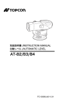
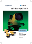
取扱説明書 /INSTRUCTION MANUAL
自動レベル /AUTOMATIC LEVEL
AT-B2/B3/B4
FC10386-A011-01
SURVEYING INSTRUMENTS
SURVEYING INSTRUMENTS
取扱説明書
自動レベル
AT-B2/B3/B4
このたびは自動レベル AT-B2/B3/B4 をお買い上
げいただき、ありがとうございます。
・ この取扱説明書は、実際に機械を操作しながら
お読みください。常に適切な取り扱いと、正し
い操作でご使用くださいますようお願いいたし
ます。
・ご使用前には、標準品が全てそろっているかご
確認ください。
C「8. 標準品一式(格納図)」
・ 扱いやすく、より良い製品をお届けするため、
常に研究・開発を行っております。製品の外観
および仕様は、改良のため、予告なく変更され
ることがありますので、あらかじめご了承くだ
さい。
・ 本書の内容は予告なく変更することがあります
ので、あらかじめご了承ください。
・ イラストは AT-B2 をもとにしています。
・ 掲載のイラストは、説明を分かりやすくするた
めに、実際とは多少異なる表現がされている場
合があります。あらかじめご了承ください。
目次
1.
2.
3.
4.
5.
安全にお使いいただくために.......................................... 1
使用上の注意 ................................................................................ 5
AT-B2/B3/B4 の特徴 ......................................................... 7
各部の名称 ...................................................................................... 8
測定準備 ............................................................................................ 9
5.1 測定準備 .............................. 9
5.2 視準をする ........................... 11
6. 測定方法 .........................................................................................13
6.1 高低差を測定する ..................... 13
6.2 水平角を測定する ..................... 15
6.3 距離を測定する ....................... 16
7. 機械の点検・調整 ..................................................................17
7.1 円形気泡管 ........................... 17
7.2 自動補正機構 ......................... 18
7.3 焦点板十字線 ......................... 19
8. 標準品一式(格納図).........................................................21
9. 特別付属品 ...................................................................................23
10.仕様 ....................................................................................................27
ii
1. 安全にお使いいただくために
この取扱説明書には、製品を安全にお使いいただき、
お使いになる人や他の人への危害、財産への損害を未
然に防ぐために、必ずお守りいただきたいことが、表
示されています。
その内容と図記号の意味は次のようになっています。
内容をよく理解してから本文をお読みください。
表示の意味
警告
この表示を無視して、誤った取り
扱いをすると、使用者が死亡また
は重傷を負う可能性が想定される
内容を示しています。
C
注意
この表示を無視して、誤った取り
扱いをすると、使用者が軽傷を負
う可能性が想定される内容および
物的損害のみの発生が予想される
内容を示しています。
J
この図記号は注意(警告を含む)を促す事項
があることを示しています。
この図の中や近くに、具体的な注意内容が書
かれています。
D
この図記号は禁止事項があることを示してい
ます。
この図の中や近くに、具体的な禁止内容が書
かれています。
I
この図記号は必ず行っていただきたい事項が
あることを示しています。
この図の中や近くに、具体的な指示内容が書
かれています。
C
1
1.
安全にお使いいただくために
全体について
C
D
禁止
D
禁止
E
指示
警告
望遠鏡で太陽を絶対に見ないでください。失
明の原因になります。
望遠鏡で反射プリズムなど反射物からの太陽
光線を見ないでください。失明の原因になり
ます。
格納ケースを本体に入れて持ち運ぶ際には、
必ず格納ケースの掛け金をすべて締めてくだ
さい。本体が落下してケガをする恐れがあり
ます。
C
注意
D
格納ケースを踏み台にしないでください。す
べりやすくて不安定です。転げ落ちてケガを
する恐れがあります。
禁止
D
禁止
D
禁止
格納ケースの掛け金・ベルトが傷んでいたら
機器を収納しないでください。ケースや機器
が落下して、ケガをする恐れがあります。
垂球を振り回したり、投げたりしないでくだ
さい。人に当たり、ケガをする恐れがありま
す。
2
1.
安全にお使いいただくために
三脚について
C
注意
E
機械を三脚に止めるときは、定心かんを確実
に締めてください。不確実だと機械が落下し
て、ケガをする恐れがあります。
指示
E
指示
D
禁止
E
指示
E
指示
機械をのせた三脚は、蝶ねじを確実に締めて
ください。不確実だと三脚が倒れ、ケガをす
る恐れがあります。
三脚の石突きを人に向けて持ち運ばないでく
ださい。人に当たり、ケガをする恐れがあり
ます。
三脚を立てるときは、脚もとに人の手・足が
ないことを確かめてください。手・足を突き
刺して、ケガをする恐れがあります。
持ち運びの際は、蝶ねじを確実に締めてくだ
さい。ゆるんでいると脚が伸び、ケガをする
恐れがあります。
3
1.
安全にお使いいただくために
標尺について
C
警告
D
雷が発生する天候下では使わないでくださ
い。標尺は導電体ですので、落雷を受けて死
傷する恐れがあります。
禁止
E
指示
高圧線・変電設備の近くで使用する際は取扱
いに十分注意してください。標尺は導電体で
すので、接触すると感電の恐れがあります。
4
2. 使用上の注意
全体について
・ 本機は精密機械です。取り扱いには十分注意してく
ださい。特に振動・衝撃・ほこり・水分・湿気はな
るべくさけてください。
・ ねじ部を傷める原因となりますので、機械を直接土
の上に置かないでください。
・ 機械を三脚上につけたまま一時使わないときは、レ
ンズキャップを付け、付属のビニールカバーで全体
を覆ってください。
・ 付属品類は、運搬中に移動しないように所定の位置
に納めてください。
メンテナンスについて
・ 使用前には、三脚各部の点検を行なってください。
・ 作業中、雨がかかった場合は水分を良く拭き取って
ください。
・ 測量終了後、格納の際は必ず機械各部の清掃をして
ください。特にレンズは息でくもらせ、きれいな布
(洗いざらしの木綿が良い)または柔かいテッシュ
ペーパーで軽く拭いてください。
・ 機械および格納ケースが汚れた場合は、水または薄
めた中性洗剤に浸したやわらかい布を固く絞って汚
れをふきとってください。アルカリ性洗剤や有機溶
剤は使用しないでください。
・ 三脚は、長期間使用すると石突き部のゆるみ・蝶ね
じの破損などが原因でガタが生じる場合がありま
す。時々各部の点検・締め直しを行ってください。
・ 機械の回転部分、ねじの部分に異物が入ったと思わ
れる時や、望遠鏡内部のレンズ、プリズム等に水滴
5
2.
使用上の注意
の跡やカビ等を発見した時は、すみやかに最寄りの
営業担当までご連絡ください。
・ 常に高い精度を保持するため、年間 1 ~ 2 回の定期
点検、検査をお勧めします。その際は、最寄りの営
業担当までご連絡ください。
免責事項
・ 火災、地震、第三者による行為、その他の事故、使
用者の故意または過失、誤用、その他異常な条件下
での使用により生じた損害に対して、当社は一切責
任を負いません。
・ 本機器の使用または使用不能から生じた付随的な損
害(データの変化・消失、事業利益の損失、事業の
中断など)に対して、当社は一切責任を負いませ
ん。
・ 取扱説明書で説明された以外の使い方によって生じ
た損害に対して、当社は一切責任を負いません。
・ 接続機器との組み合わせによる誤動作などから生じ
た損害に対して、当社は一切責任を負いません。
6
3. AT-B2/B3/B4 の特徴
短視準型自動レベル AT-B2/B3/B4 は、独自開発による
磁気制動方式の自動補正機構を内蔵しています。その
ため、わずかな傾きは、自動的に補正することがで
き、温度変化・衝撃に対しても安定性があります。
また、簡単な水平角測定機能・水平距離測定機能も付
いておりますので、土木・建築・各種工事に威力を発
揮します。
D
・ 正しく調整された自動レベルでは、気泡が円形気泡
管内側の○内であれば自動補正機構により水平が保
たれます。
7
4. 各部の名称
1
2
3
( イラストは AT-B2)
4
5
6
7
9
8
10
14
13
11
12
1. 日よけ(AT-B2 のみ)
2. 反射プリズム(AT-B2)/ 反射鏡(AT-B3/B4)
3. ピープサイト *1
4. 円形気泡管調整ねじ
5. 円形気泡管
6. 整準ねじ
7. 底板
8. 全周微動つまみ
9. 対物レンズ
10. 合焦つまみ
11. 水平目盛盤回転リング
12. 水平目盛盤窓
13. 調整ねじカバー
14. 接眼レンズ *2
*1
*2
AT-B4 はガンサイトとなります。
AT-B2 の接眼レンズは着脱式です。
8
5. 測定準備
5.1 測定準備
1
三脚の下部のバンドをはずし、固定ねじをゆるめ
ます。
2
三脚の脚先を閉じたまま地面につけ、脚頭が目の
高さになるまで脚を伸ばし、固定ねじを締めま
す。
3
脚先が正三角形になるように三脚を広げます。
4
脚頭をほぼ水平にしてから、石突を踏み込み、三
脚をしっかりと据え付けます。
9
5.
測定準備
5
機械を脚頭にのせ、定心かんで固定します。
6
球面脚頭の場合、定心かん
を少しゆるめ、底板を両手
で持って脚頭上をすべら
せ、円形気泡管の○付近に
気泡を導きます。
7
定心かんを締めます。
8
整準ねじを回して、気泡を
○の中央に入れます。
10
5.
測定準備
5.2 視準をする
1
ピープサイトまたはガンサ
イトを使って、対物レンズ
を目標物に向けます。
2
接眼レンズを徐々に回し
て、焦点板十字線がぼける
寸前で止めます。
3
全周微動つまみを回して視
野の中央近くに目標物を入
れ、合焦つまみを回して目
標物にピントを合わせま
す。
D
・ AT-B2 の合焦つまみは軽く回
わる微動と少し重く感じる
粗動の 2 段階で働きます。
粗動で概略ピントを合わせ、
微動で戻しながら正確に目
標物にピントを合わせます。
4
望遠鏡をのぞきながら目を
少し上下左右に振ってみま
す。
11
5.
5
測定準備
目標像と焦点十字線が相対
的にずれなければ測定準備
完了です。ずれる場合は、
2 から合わせ直してくださ
い。
D
・
5 でずれるような状態だと、測定値に誤差が生じま
す。ピント合わせはしっかり行なってください。
・ 光が強すぎる時は日よけをお使いください。(AT-B2
のみ)
12
6. 測定方法
6.1 高低差を測定する
1
地点 AB のほぼ中央にレベルを据え付けます。この
時スタジア線を使用すると便利です。
C「6.3 距離を測定する」
D
・ 機械を A、B 二点の中央に正確に置いて観測すれば
視準軸の水平が少し狂っていても結果に影響せず誤
差を生じません。なるべく中央に据えてください。
2
A 点に標尺をまっすぐに立て、値 a(後視)を読み
とります。
3
B 点にも標尺を立てて視準し、値 b(前視)を読み
とります。
13
6.
4
測定方法
差 a-b を計算すると、高低差が求まります。
計算例
h=a-b=1.735m-1.224m=0.511m
よって B 点の方が A 点より 0.511m 高いことがわ
かります。
(B 点が A 点より低ければマイナスの符号が付きま
す。
)
<AB 間の距離が長い場合、または高低差が大きい場合 >
1
図 5.2 のように偶数の区間に分けて観測します。
2
計算は下記のように行ないます。
高低差 = 後視の総和 - 前視の総和
求める点の標高 = 既知点の標高 + 高低差
D
・ 測定精度を上げる場合には、A から B へ、B から A
へ観測して、閉合誤差を計算することをお勧めしま
す。
14
6.
測定方法
6.2 水平角を測定する
水平目盛は、時計回りにふられています。したがっ
て、向って左から右へ視準するようにしてください。
1
垂球をおろして、測点上に機械を据えます。
2
A 点を視準し、水平目盛盤窓を見ながら水平目盛
盤回転リングを回して 0°に合わせます。
3
B 点を視準して目盛盤窓の値を読みます。
下図では 91.5°です。
15
6.
測定方法
6.3 距離を測定する
望遠鏡の焦点板には、スタジア線が入っており、簡単
な測距(スタジア測量)ができます。
1
2
標尺を視準して、スタジア線に挟まれた長さ l
(cm)を測定します。
標尺上で測定した cm の値をそのまま m の単位にお
きかえれば、標尺までの距離になります。
例 スタジア線に挟まれた長さが 32cm の時、標尺ま
での距離 l は 32m になります。
16
7. 機械の点検・調整
7.1 円形気泡管
1
整準ねじを使って気泡を○
の中央に入れます。
2
本体を180°回転させます。
気泡が○の中にあれば調整は不要です。気泡が
○におさまらないときは、次の調整を行ってく
ださい。
3
整準ねじでずれ量の半分を
戻します。
4
あとの半分を六角棒レンチ
を使い、円形気泡管調整ね
じを回して、○内に気泡を
入れてください。
5
再度望遠鏡を反転して、気
泡が○の中にあれば調整完
了です。
17
7.
機械の点検・調整
7.2 自動補正機構
1
気泡が○の中央に入るように機械を据えてくださ
い。
2
視準軸に近い整準ねじ1ヶを左右それぞれ1/8回転
し、十字線の動きを見てください。
(または、見やすい目標物を視準しながら脚、本
体などを軽くたたいてみてください。
)
一瞬、十字線がずれますが、すぐ元に戻れば正
常です。使用前には必ずチェックしてください。
18
7.
機械の点検・調整
7.3 焦点板十字線
1
30 ~ 50m 離れた A・B の中央で a1・b1 を読みとりま
す。
2
点 A から 2m の地点に機械を据え、
再び a2・b2 を読み
とります。
この時、望遠鏡は点 B を視準したままにしておき
ます。
b2'=a2-(a1-b1)を計算して b2'=b2 ならば焦点板十字
線は正常です。等しくならない時は次の調整をしてく
ださい。
19
7.
機械の点検・調整
3
調整ねじカバーを左に回してはずします。
4
調整ピン(C「8. 標準品一式(格納図)」
)を
使って、b2'=b2 になるまで調整します。例えば、
2 の図の場合、b2 の値が大きすぎるので、十字線
を下げる必要があります。この場合は調整ねじを
少しゆるめてください。また、十字線を上げたい
ときは調整ねじを締めてください。
5
再び 1 ~ 2 までの点検を行ない、完全になるまで
調整します。
20
8. 標準品一式(格納図)
AT-B2
2
3
4
1
8
1.
2.
3.
4.
5.
6.
7.
8.
7
6
5
ケース:SE35A
本体...................... 1
垂球...................... 1
六角棒レンチ.............. 1
調整ピン.................. 2
取扱説明書................ 1
ビニールカバー............ 1
シリコーンクロス.......... 1
レンズキャップ............ 1
21
8.
標準品一式(格納図)
AT-B3/B4
14
2
15
3
16
4
20
8
1
19
7
1.
2.
3.
4.
5.
6.
7.
8.
17
5 18
6
ケース:SE49A
本体...................... 1
垂球...................... 1
六角棒レンチ.............. 1
調整ピン.................. 1
取扱説明書................ 1
ビニールカバー............ 1
シリコーンクロス.......... 1
レンズキャップ............ 1
22
9. 特別付属品
● 照明装置 LA8(AT-B2 用)
夜間や暗い所での測定には、オプションの照明装置
LA8 が便利です。
1
上の図のように、照明装置の枠を望遠鏡の対物レ
ンズ側にはめ込んでください。
(日よけを引っ込めてから取り付けてください。)
2
ボリュームを右に回すとスイッチが入り、光量が
強くなっていきます。
● 光学マイクロメーター OM5(AT-B2 用)
高精度水準測量のために着脱式の顕微鏡付光学マイク
ロメーター OM5 が用意されております。マイクロメー
ターのつまみを回すと、望遠鏡の視準軸は最大 10mm
上下に移動し、その移動量は 1 目盛 0.1mm 単位で測定
できます。
(最短視準距離 :1m)
標尺は 1cm 間隔に目盛った一等標尺または同様の精密
尺度を使用してください。
23
9.
特別付属品
マイクロメーターつまみ
マイクロメーター
接眼レンズ
1
光学マイクロメーターを望遠鏡に載せて、取り付
けレバーで固定します。
(日よけを引っ込めてから取り付けてください。)
2
マイクロメーターつまみを回し、視準軸を移動さ
せて、標尺の目盛を焦点板のくさび形の線の間に
挟み込みます。
3
マイクロメーター接眼レンズをのぞいて、マイク
ロ目盛を読みとります。1 目盛が 0.1mm です。
4
標尺目盛の読みとマイクロ目盛の読みを加えると
測定値となります。
24
9.
特別付属品
標尺の読み
マイクロメーターの読み
152
cm
+ 8.7mm
152.87cm
G
・ マイクロメーターつまみは必ず時計回り方向に回し
て、標尺目盛を挟むようにしてください。
● ダイアゴナルアイピース DE16/DE22
機械の後にまわれない時は、オプションのダイアゴナ
ルアイピースが便利です。
AT-B2 用ダイアゴナル
アイピース DE16
AT-B3/B4 用ダイアゴナル
アイピース DE22
1
AT-B2 は接眼レンズを左に回してはずしてからダ
イアゴナルアイピースをねじ込んで取り付けま
す。
AT-B3/B4 は調整ねじカバーにダイアゴナルアイ
ピースをかぶせます。
2
接続部を軽く押さえながらダイアゴナルアイピー
スの接眼つまみを回して、焦点板十字線にピント
を合わせます。
以下は「5.2 視準をする」にならってご使用くださ
い。
25
9.
特別付属品
D
・ AT-B2 の接眼レンズは着脱式となっておりますの
で、取りはずして交換接眼レンズ(EL5)を使用す
ることができます。
● 交換接眼レンズ EL5(AT-B2 用)
標準の接眼レンズと交換することにより、倍率を 40
倍にして測定できます。
26
10. 仕様
AT-B2
AT-B3
AT-B4
望遠鏡
全長
215mm
像
正像
有効径
42mm
36mm
32mm
倍率
32 ×
28 ×
24 ×
視野(100m)
分解力
1°20'
(2.3m)
3.0"
最短合焦距離
1°25'
(2.5m)
3.5"
4.0"
0.3m(機械中心より)
スタジア乗数、加数
100,0
水平目盛盤
直径
103mm
最小読取値
1°
自動補正機構
範囲
± 15'
円形気泡管
感度
10'/2mm
1km 往復標準偏差
0.7mm
光学マイクロメーター
使用時
防水性能
0.5mm
1.5mm
2.0mm
─────
IPx6(JIS C 0920-2003)
使用温度範囲
-20 ~ 50 ℃
保存温度範囲
-40 ~ 70 ℃
27
10.
寸法
仕様
幅
130mm
長さ
215mm
高さ
質量
140mm
1.85kg
28
135mm
1.7kg
SURVEYING INSTRUMENTS
INSTRUCTION MANUAL
AUTOMATIC LEVEL
AT-B2/B3/B4
Thank you for selecting the AT-B2/B3/B4.
• Please read this instruction manual carefully
before using this product.
• Verify that all equipment is included.
C"8. STANDARD EQUIPMENT"
• The specifications and general appearance of
the instrument are subject to change without
prior notice and without obligation by Topcon
Corporation. and may differ from those appearing in this manual.
• The content of this manual is subject to change
without notice.
• Illustrations appearing in this manual are of
AT-B2.
• Some of the diagrams shown in this manual may
be simplified for easier understanding.
CONTENTS
1.
2.
3.
4.
5.
PRECAUTIONS FOR SAFE OPERATION ..... 1
PRECAUTIONS .............................................. 5
FEATURES OF AT-B2/B3/B4 ......................... 7
PARTS OF THE INSTRUMENT ...................... 8
PRELIMINARIES ............................................ 9
5.1
5.2
SETTING UP THE INSTRUMENT .................9
FOCUSSING AND SIGHTING ..................... 11
6. OPERATION ................................................. 13
6.1
6.2
6.3
MEASURING HEIGHT DIFFERENCE .........13
MEASURING HORIZONTAL ANGLE ..........15
MEASURING DISTANCE USING
THE STADIA LINES .....................................16
7. CHECKS AND ADJUSTMENTS ................... 17
7.1
7.2
7.3
CIRCULAR LEVEL .......................................17
AUTOMATIC COMPENSATOR ...................18
RETICLE CROSS-LINE (LINE OF SIGHT) ..19
8. STANDARD EQUIPMENT ............................ 21
9. OPTIONAL ACCESSORIES ......................... 23
10.SPECIFICATIONS ......................................... 27
ii
1. PRECAUTIONS FOR SAFE OPERATION
For the safe use of the product and prevention of injury
to operators and other persons as well as prevention of
property damage, items which should be observed are
indicated by an exclamation point within a triangle used
with WARNING and CAUTION statements in this
instruction manual.
The definitions of the indications are listed below. Be
sure you understand them before reading the manual's
main text.
Definition of Indication
C
C
J
D
I
WARNING
Ignoring this indication and
making an operation error
could possibly result in death or
serious injury to the operator.
CAUTION
Ignoring this indication and
making an operation error
could possibly result in minor
injury or property damage.
This symbol indicates items for which caution
(hazard warnings inclusive) is urged. Specific
details are printed in or near the symbol.
This symbol indicates items which are
prohibited. Specific details are printed in or
near the symbol.
This symbol indicates items which must
always be performed. Specific details are
printed in or near the symbol.
1
1. PRECAUTIONS FOR SAFE OPERATION
GENERAL
C
WARNING
D
Never look at the sun through the telescope.
Loss of eyesight could result.
D
Do not look at reflected sunlight from a prism
or other reflecting object through the
telescope. Loss of eyesight could result.
E
When securing the instrument in the carrying
case make sure that all catches, including the
side catches, are closed. Failure to do so could
result in the instrument falling out while being
carried, causing injury.
C
CAUTION
D
Do not use the carrying case as a footstool.
The case is slippery and unstable so a person
could slip and fall off it.
D
Do not place the instrument in a case with a
damaged catch or belt. The case or instrument
could be dropped and cause injury.
D
Do not wield or throw the plumb bob. A person
could be injured if struck.
2
1. PRECAUTIONS FOR SAFE OPERATION
TRIPOD
C
CAUTION
E
When mounting the instrument to the tripod,
tighten the centring screw securely. Failure to
tighten the screw properly could result in the
instrument falling off the tripod causing injury.
E
Tighten securely the leg fixing screws of the
tripod on which the instrument is mounted.
Failure to tighten the screws could result in the
tripod collapsing, causing injury.
D
Do not carry the tripod with the tripod shoes
pointed at other persons. A person could be
injured if struck by the tripod shoes.
E
Keep hands and feet away from the tripod
shoes when fixing the tripod in the ground. A
hand or foot stab wound could result.
E
Tighten the leg fixing screws securely before
carrying the tripod. Failure to tighten the
screws could lead to the tripod legs extending,
causing injury.
3
1. PRECAUTIONS FOR SAFE OPERATION
STAFF
C
WARNING
D
Do not use under thunderous weather
conditions. Staff is conductive and if struck by
lightning, death or injury could result.
E
Handle with care when using near high voltage
cables or transformers. Staff is conductive and
contact could result in electric shock.
4
2. PRECAUTIONS
GENERAL
• The AT-B2/B3/B4 is a precision instrument.
Handle with care and avoid heavy shocks and
vibration.
• Never place the instrument directly on the ground.
• When the instrument is left on the tripod, cap the
objective lens and cover the entire instrument with
the vinyl cover provided.
• When the instrument is placed in the case, store the
accessories in their specified places.
MAINTENANCE
• Wipe off moisture completely if the instrument gets
wet during survey work.
• Always clean the instrument before returning it to the
case. The lens requires special care. Dust it off with a
clean cloth first to remove tiny particles. Then, after
providing a little condensation by breathing on the
lens, wipe it with a soft clean cloth or lens tissue.
• To clean the instrument or carrying case, lightly
moisten a soft cloth in a mild detergent solution.
Wring out excess water until the cloth is slightly
damp, then carefully wipe the surface of the unit. Do
not use any organic solvents or alkaline cleaning
solutions.
• Check the tripod for loose fit and loose screws.
• If any trouble is found on the rotatable portion, screws
or optical parts (e.g. lens), contact your local dealer.
• Check the instrument for proper adjustment
periodically to maintain the instrument accuracy.
5
2. PRECAUTIONS
EXCEPTIONS FROM RESPONSIBILITY
• The user of this product is expected to follow all
operating instructions and make periodic checks
(hardware only) of the product's performance.
• The manufacturer, or its representatives, assumes no
responsibility for results of a faulty or intentional
usage or misuse including any direct, indirect,
consequential damage, and loss of profits.
• The manufacturer, or its representatives, assumes no
responsibility for consequential damage, and loss of
profits due to any natural disaster, (earthquake,
storms, floods etc.), fire, accident, or an act of a third
party and/or a usage under unusual conditions.
• The manufacturer, or its representatives, assumes no
responsibility for any damage, and loss of profits due
to a change of data, loss of data, an interruption of
business etc., caused by using the product or an
unusable product.
• The manufacturer, or its representatives, assumes no
responsibility for any damage, and loss of profits
caused by usage different to that explained in the
instruction manual.
• The manufacturer, or its representatives, assumes no
responsibility for damage caused by incorrect
operation, or action resulting from connection to other
products.
6
3. FEATURES OF AT-B2/B3/B4
The AT-B2/B3/B4 is equipped with a fast-action,
magnetically-damped, automatic compensator. After
the instrument has been approximately leveled using
the circular level, the line of sight is accurately leveled
by the automatic compensating mechanism.
The AT-B2/B3/B4 has been designed to allow stable
surveying operations regardless of environmental
conditions such as vibration and temperature changes.
The AT-B2/B3/B4 has a simple horizontal circle for
angle measurement, and the stadia lines on the reticle
can be used for approximate distance measurement.
The AT-B2/B3/B4 is ideally suited for general survey
work, civil engineering and construction work.
$
• The instrument is accurately leveled when the
bubbleis within the center circle of the circular level.
7
4. PARTS OF THE INSTRUMENT
(Instrument shown: AT-B2)
1
2
3
4
5
6
9
7
8
10
14
13
11
12
1. Lens hood (AT-B2 only)
2. Prism (AT-B2)/Reflector (AT-B3/B4)
3. Peep sight*1
4. Circular level adjusting screw
5. Circular level
6. Leveling foot screw
7. Base plate
8. Horizontal fine motion screw
9. Objective lens
10. Focussing knob
11. Horizontal circle positioning ring
12. Horizontal circle window
13. Reticle adjusting screw cover
14. Eyepiece*2
*1 The AT-B4 has a gun sight.
*2 The AT-B2 eyepiece is detachable.
8
5. PRELIMINARIES
5.1 SETTING UP THE INSTRUMENT
1
Unbuckle the band around the tripod legs and
loosen the extension clamp screws.
2
With the tripod closed, extend the tripod legs until
the tripod head is roughly at eye level, then retighten the clamp screws.
3
Spread the tripod legs so that the leg tips form a
regular triangle on the ground.
4
Make sure that the tripod head is approximately
level. Fix the tripod shoes firmly into the ground.
9
5. PRELIMINARIES
5
Hold the instrument on the tripod head and tighten
the centering screw.
6
When using the spherical head
tripod, slightly loosen the
centering screw, hold the base
plate in both hands, and slide it
across the tripod head until the
bubble is in the proximity of the
circular level.
7
Tighten the centering screw.
8
Adjust the leveling foot screws
until the bubble is exactly
centered in the center circle.
10
5. PRELIMINARIES
5.2 FOCUSSING AND SIGHTING
1
Use the peep sight or gun
sight to point the objective
lens at the target.
2
Gradually turn the eyepiece
until just before the reticle
cross-line becomes blurred.
3
Use the horizontal fine
motion screw to center the
target in the field of view.
Turn the focussing knob to
focus on the target.
$
• Focussing is coarse while the
AT-B2 focussing knob feels
heavy to rotate. Rotating in
the reverse direction (less
heavy) will give a fine
focussing motion.
4
Looking through the
telescope, shift your eyes
slightly in the horizontal and
vertical directions.
11
5. PRELIMINARIES
5
If there is no parallax
between the target image
and the reticle, preparations
for measurement are
complete. If there is
parallax, repeat the above
procedure from step 2 in
order to refocus the reticle.
$
• If there is parallax, measurement errors may result,
so make sure to adequately focus the target.
• Use the lens hood (AT-B2 only) in strong light
conditions.
12
6. OPERATION
6.1 MEASURING HEIGHT DIFFERENCE
1
Set up the instrument at a point approximately
halfway between points A and B. The reticle stadia
lines can be used to optically compare the
distances. (See "6.3 MEASURING DISTANCE
USING THE STADIA LINES".)
$
• For more accurate measurement, set the instrument
as close to halfway as possible, to eliminate errors
due to sighting axis misalignment.
2
Position the staff vertically at point A.
Take the reading a (backsight) on the staff at point
A.
3
Then sight the staff at point B and obtain the
reading b (foresight).
4
The difference a - b is the height difference h of B
from A.
Example:
h = a - b = 1.735m - 1.224m = 0.511m
13
6. OPERATION
Therefore point B is 0.511m higher than point A.
(The value of h will be negative if point B is lower
than point A.)
<When the distance between points A and B is large
or if the height difference is great>
1
Divide the distance into a number of sections and
determine the height difference of each section.
2
The height difference between points A and B is
the total of the height differences of all the
sections.
The general formula is:
Altitude of the required point = altitude of known
point + total of backsight values - total of foresight
values.
$
• This simple leveling technique has no error check. It
is better to measure from A to B and back to A so that
the error of closure can be calculated.
14
6. OPERATION
6.2 MEASURING HORIZONTAL ANGLE
The horizontal circle graduations are annotated every
10° (360°) or 10 gon (400 gon) in a clockwise direction.
As a result, sighting is performed from left to right.
1
Use the plumb bob to set up the instrument directly
above the survey point.
2
Sight point A, and set the horizontal circle to 0° by
turning the horizontal circle positioning ring.
3
Sight point B and take the angle reading.
Example: 91.5° (or 91.5 gon) in the figure below.
15
6. OPERATION
6.3 MEASURING DISTANCE USING THE
STADIA LINES
The stadia lines etched on the reticle can be used for
distance measurements.
1
Sight the staff, and count the number of
centimeters, l, between the two stadia lines.
2
This number is equivalent to the distance in
meters between the staff and the instrument.
Example:
If the length (l) is 32 cm, the horizontal distance
from the instrument center A to the staff B is 32 m.
16
7. CHECKS AND ADJUSTMENTS
7.1 CIRCULAR LEVEL
1
Adjust the leveling foot
screws to center the
bubble in the circular level.
2
Turn the instrument 180°
(or 200 gon).
If the bubble is inside the circle, no adjustment is
necessary. If the bubble shifts from within the
circle, adjust as follows:
3
Compensate for one-half of
the shift by adjusting the
leveling foot screws.
4
Eliminate the remaining
half shift with the circular
level adjusting screws
using the hexagonal
wrench.
5
Turn the instrument 180°
(or 200 gon). If the bubble
remains in the circle,
adjustment is complete.
17
7. CHECKS AND ADJUSTMENTS
7.2 AUTOMATIC COMPENSATOR
1
Center the bubble in the circular level.
2
While turning the nearest leveling screw to the
sighting axis 1/8 of a turn to the right or left, check
the movement of the horizontal cross-line.
(Another method is to tap the tripod legs or the
main body while sighting a clear target.)
If the automatic compensator mechanism is
working normally the cross-line should bounce,
then immediately return to the original position.
It is advisable to check the movement of the
automatic compensator before use.
18
7. CHECKS AND ADJUSTMENTS
7.3 RETICLE CROSS-LINE (LINE OF SIGHT)
1
Set the instrument halfway between two points, A
and B, 30 to 50m apart. Take readings a1 and b1.
2
Set the instrument at a point 2 m from point A.
Take readings a2 and b2.
Leave the telescope sighted on point B.
Calculate
b2’ = a2 - (a1 - b1)
If b2’ = b2, the horizontal cross-line is normal and
no adjustment is necessary.
When b2’ and b2 are different, adjust the cross-line
as follows:
19
7. CHECKS AND ADJUSTMENTS
3
Unscrew and remove the adjusting screw cover.
4
Use the adjusting pin to eliminate the difference
between b2’ and b2. (See "8. STANDARD
EQUIPMENT".) In the example shown in step 2
b2’ is larger than b2. The horizontal line needs to
be lowered. To lower the horizontal line, carefully
loosen the adjusting screw by a small amount
using the adjusting pin. To raise the horizontal
line, tighten the adjusting screw.
5
Repeat steps 1 and 2 of the adjustment
procedure until the difference between b2’ and b2 is
small.
20
8. STANDARD EQUIPMENT
AT-B2
(Packing layout)
2
3
4
1
8
1.
2.
3.
4.
5.
6.
7.
8.
7
6
5
Main unit ................................ 1
Plumb bob ............................. 1
Hexagonal wrench ................. 1
Adjusting pin .......................... 2
Instruction manual ................. 1
Vinyl cover ............................. 1
Cleaning cloth........................ 1
Lens cap ................................ 1
21
Case: SE35A
8. STANDARD EQUIPMENT
AT-B3/B4
(Packing layout)
14
2
15
3
16
4
208
1
19
7
1.
2.
3.
4.
5.
6.
7.
8.
Case: SE49A
17
5 18
6
Main unit ................................ 1
Plumb bob ............................. 1
Hexagonal wrench ................. 1
Adjusting pin .......................... 2
Instruction manual ................. 1
Vinyl cover ............................. 1
Cleaning cloth........................ 1
Lens cap ................................ 1
22
9. OPTIONAL ACCESSORIES
• ILLUMINATION PACK LA8 (AT-B2 only)
The illumination pack, LA8, is available for use when
leveling in low light conditions.
1
Slide it onto the telescope as far as it will go. (The
lens hood should be retracted.)
2
Switch the unit on and adjust the brightness using
the knob.
• OPTICAL MICROMETER OM5 (AT-B2 only)
The detachable optical micrometer OM5 is available for
high precision leveling. Turning the micrometer knob
shifts the line of sight of the telescope vertically a
maximum of 10 mm. This micrometer shift can be
displayed in 0.1 mm graduations. (Minimum sighting
distance: 1 m)
Use first order staves with 1 cm graduations or similar
precision staves.
23
9. OPTIONAL ACCESSORIES
1
Mount the OM5 on the telescope of the AT-B2 and
push the locking lever fully forward to lock it. (The
lens hood should be retracted.)
2
Turn the micrometer knob to move the line of sight
until the graduation mark on the staff comes to the
middle point between the two wedge reticle lines
for an accurate reading.
3
Take the micrometer reading in the micrometer
eyepiece. One division corresponds to 0.1 mm.
4
Adding the micrometer reading to the staff
graduations reading gives the measurement value.
24
9. OPTIONAL ACCESSORIES
Example:
Staff graduation
Micrometer
152
+
cm
8.7 mm
152.87 cm
G
• For accurate measurement, the last adjustment of
the micrometer knob should be in the clockwise
direction.
• DIAGONAL EYEPIECE DE16/DE22
The diagonal eyepiece DE16/DE22 is available for use
in restricted viewing positions.
DE16 for AT-B2
DE22 for AT-B3/B4
1
To attach the DE16, remove the eyepiece by
unscrewing to the left, and screw in the diagonal
eyepiece.
To attach the DE22, push it on to the reticle
adjusting screw cover.
2
Holding the base of the DE16/DE22, focus on the
reticle by turning the eyepiece of the DE16/DE22.
Perform focussing and sighting as described in "5.2
FOCUSSING AND SIGHTING"
25
9. OPTIONAL ACCESSORIES
$
• The AT-B2 detachable eyepiece can also be
replaced by the optional 40x eyepiece (EL5).
• REMOVABLE EYEPIECE EL5 (AT-B2 only)
Increases the standard 32X image to 40X.
26
10. SPECIFICATIONS
AT-B2
Telescope
Length
Image
Objective aperture
AT-B3
AT-B4
215mm (8.46 in.)
Erect
42mm
36mm
32mm
(1.65 in.)
(1.42 in.)
(1.26 in.)
Magnification
32X
28X
24X
1°25'
Field of view
1°20'
(2.3m/7.5ft.)
(2.5m/8.2ft.)
(at 100m/328ft.)
Resolving power
3.0"
3.5"
4.0"
Minimum focus
0.3m (1ft.)
Stadia ratio
1:100
Additive constant
0
Horizontal circle
Diameter
103mm (4.1in.)
Graduation
1° / 1gon
Automatic compensator
Range
±15'
Circular level
Sensitivity
10' / 2mm
Standard deviation for 1 km of double run leveling
1.5mm
2.0mm
0.7mm
(0.03in.)
With micrometer
(0.06in.)
(0.08in.)
0.5mm
(0.02in.)
Water resistance
Operating temperature
range
Storage temperature
range
IPx6 (IEC60529:2001)
-20 to 50°C (-4 to 122°F)
-40 to 70°C (-40 to 158°F)
27
Size
Width
Length
Height
130mm (5.12in.)
215mm (8.46in.)
140mm
135mm
(5.51in.)
Weight
(5.31in.)
1.85kg
1.7kg
(4.1 lbs)
(3.7 lbs)
28
This is the mark of the Japan Surveying Instruments Manufacturers
Association.
http://www.topcon.co.jp
Please see the attached address list or the following website for contact addresses.
GLOBAL GATEWAY http://global.topcon.com/
http://www.topcon.co.jp