1
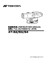
取扱説明書 /INSTRUCTION MANUAL
自動レベル /AUTOMATIC LEVEL
AT-B2/B3/B4
FC10386-A011-01
SURVEYING INSTRUMENTS
INSTRUCTION MANUAL
AUTOMATIC LEVEL
AT-B2/B3/B4
Thank you for selecting the AT-B2/B3/B4.
• Please read this instruction manual carefully
before using this product.
• Verify that all equipment is included.
C"8. STANDARD EQUIPMENT"
• The specifications and general appearance of
the instrument are subject to change without
prior notice and without obligation by Topcon
Corporation. and may differ from those appearing in this manual.
• The content of this manual is subject to change
without notice.
• Illustrations appearing in this manual are of
AT-B2.
• Some of the diagrams shown in this manual may
be simplified for easier understanding.
CONTENTS
1.
2.
3.
4.
5.
PRECAUTIONS FOR SAFE OPERATION ..... 1
PRECAUTIONS .............................................. 5
FEATURES OF AT-B2/B3/B4 ......................... 7
PARTS OF THE INSTRUMENT ...................... 8
PRELIMINARIES ............................................ 9
5.1
5.2
SETTING UP THE INSTRUMENT .................9
FOCUSSING AND SIGHTING ..................... 11
6. OPERATION ................................................. 13
6.1
6.2
6.3
MEASURING HEIGHT DIFFERENCE .........13
MEASURING HORIZONTAL ANGLE ..........15
MEASURING DISTANCE USING
THE STADIA LINES .....................................16
7. CHECKS AND ADJUSTMENTS ................... 17
7.1
7.2
7.3
CIRCULAR LEVEL .......................................17
AUTOMATIC COMPENSATOR ...................18
RETICLE CROSS-LINE (LINE OF SIGHT) ..19
8. STANDARD EQUIPMENT ............................ 21
9. OPTIONAL ACCESSORIES ......................... 23
10.SPECIFICATIONS ......................................... 27
ii
1. PRECAUTIONS FOR SAFE OPERATION
For the safe use of the product and prevention of injury
to operators and other persons as well as prevention of
property damage, items which should be observed are
indicated by an exclamation point within a triangle used
with WARNING and CAUTION statements in this
instruction manual.
The definitions of the indications are listed below. Be
sure you understand them before reading the manual's
main text.
Definition of Indication
C
C
J
D
I
WARNING
Ignoring this indication and
making an operation error
could possibly result in death or
serious injury to the operator.
CAUTION
Ignoring this indication and
making an operation error
could possibly result in minor
injury or property damage.
This symbol indicates items for which caution
(hazard warnings inclusive) is urged. Specific
details are printed in or near the symbol.
This symbol indicates items which are
prohibited. Specific details are printed in or
near the symbol.
This symbol indicates items which must
always be performed. Specific details are
printed in or near the symbol.
1
1. PRECAUTIONS FOR SAFE OPERATION
GENERAL
C
WARNING
D
Never look at the sun through the telescope.
Loss of eyesight could result.
D
Do not look at reflected sunlight from a prism
or other reflecting object through the
telescope. Loss of eyesight could result.
E
When securing the instrument in the carrying
case make sure that all catches, including the
side catches, are closed. Failure to do so could
result in the instrument falling out while being
carried, causing injury.
C
CAUTION
D
Do not use the carrying case as a footstool.
The case is slippery and unstable so a person
could slip and fall off it.
D
Do not place the instrument in a case with a
damaged catch or belt. The case or instrument
could be dropped and cause injury.
D
Do not wield or throw the plumb bob. A person
could be injured if struck.
2
1. PRECAUTIONS FOR SAFE OPERATION
TRIPOD
C
CAUTION
E
When mounting the instrument to the tripod,
tighten the centring screw securely. Failure to
tighten the screw properly could result in the
instrument falling off the tripod causing injury.
E
Tighten securely the leg fixing screws of the
tripod on which the instrument is mounted.
Failure to tighten the screws could result in the
tripod collapsing, causing injury.
D
Do not carry the tripod with the tripod shoes
pointed at other persons. A person could be
injured if struck by the tripod shoes.
E
Keep hands and feet away from the tripod
shoes when fixing the tripod in the ground. A
hand or foot stab wound could result.
E
Tighten the leg fixing screws securely before
carrying the tripod. Failure to tighten the
screws could lead to the tripod legs extending,
causing injury.
3
1. PRECAUTIONS FOR SAFE OPERATION
STAFF
C
WARNING
D
Do not use under thunderous weather
conditions. Staff is conductive and if struck by
lightning, death or injury could result.
E
Handle with care when using near high voltage
cables or transformers. Staff is conductive and
contact could result in electric shock.
4
2. PRECAUTIONS
GENERAL
• The AT-B2/B3/B4 is a precision instrument.
Handle with care and avoid heavy shocks and
vibration.
• Never place the instrument directly on the ground.
• When the instrument is left on the tripod, cap the
objective lens and cover the entire instrument with
the vinyl cover provided.
• When the instrument is placed in the case, store the
accessories in their specified places.
MAINTENANCE
• Wipe off moisture completely if the instrument gets
wet during survey work.
• Always clean the instrument before returning it to the
case. The lens requires special care. Dust it off with a
clean cloth first to remove tiny particles. Then, after
providing a little condensation by breathing on the
lens, wipe it with a soft clean cloth or lens tissue.
• To clean the instrument or carrying case, lightly
moisten a soft cloth in a mild detergent solution.
Wring out excess water until the cloth is slightly
damp, then carefully wipe the surface of the unit. Do
not use any organic solvents or alkaline cleaning
solutions.
• Check the tripod for loose fit and loose screws.
• If any trouble is found on the rotatable portion, screws
or optical parts (e.g. lens), contact your local dealer.
• Check the instrument for proper adjustment
periodically to maintain the instrument accuracy.
5
2. PRECAUTIONS
EXCEPTIONS FROM RESPONSIBILITY
• The user of this product is expected to follow all
operating instructions and make periodic checks
(hardware only) of the product's performance.
• The manufacturer, or its representatives, assumes no
responsibility for results of a faulty or intentional
usage or misuse including any direct, indirect,
consequential damage, and loss of profits.
• The manufacturer, or its representatives, assumes no
responsibility for consequential damage, and loss of
profits due to any natural disaster, (earthquake,
storms, floods etc.), fire, accident, or an act of a third
party and/or a usage under unusual conditions.
• The manufacturer, or its representatives, assumes no
responsibility for any damage, and loss of profits due
to a change of data, loss of data, an interruption of
business etc., caused by using the product or an
unusable product.
• The manufacturer, or its representatives, assumes no
responsibility for any damage, and loss of profits
caused by usage different to that explained in the
instruction manual.
• The manufacturer, or its representatives, assumes no
responsibility for damage caused by incorrect
operation, or action resulting from connection to other
products.
6
3. FEATURES OF AT-B2/B3/B4
The AT-B2/B3/B4 is equipped with a fast-action,
magnetically-damped, automatic compensator. After
the instrument has been approximately leveled using
the circular level, the line of sight is accurately leveled
by the automatic compensating mechanism.
The AT-B2/B3/B4 has been designed to allow stable
surveying operations regardless of environmental
conditions such as vibration and temperature changes.
The AT-B2/B3/B4 has a simple horizontal circle for
angle measurement, and the stadia lines on the reticle
can be used for approximate distance measurement.
The AT-B2/B3/B4 is ideally suited for general survey
work, civil engineering and construction work.
$
• The instrument is accurately leveled when the
bubbleis within the center circle of the circular level.
7
4. PARTS OF THE INSTRUMENT
(Instrument shown: AT-B2)
1
2
3
4
5
6
9
7
8
10
14
13
11
12
1. Lens hood (AT-B2 only)
2. Prism (AT-B2)/Reflector (AT-B3/B4)
3. Peep sight*1
4. Circular level adjusting screw
5. Circular level
6. Leveling foot screw
7. Base plate
8. Horizontal fine motion screw
9. Objective lens
10. Focussing knob
11. Horizontal circle positioning ring
12. Horizontal circle window
13. Reticle adjusting screw cover
14. Eyepiece*2
*1 The AT-B4 has a gun sight.
*2 The AT-B2 eyepiece is detachable.
8
5. PRELIMINARIES
5.1 SETTING UP THE INSTRUMENT
1
Unbuckle the band around the tripod legs and
loosen the extension clamp screws.
2
With the tripod closed, extend the tripod legs until
the tripod head is roughly at eye level, then retighten the clamp screws.
3
Spread the tripod legs so that the leg tips form a
regular triangle on the ground.
4
Make sure that the tripod head is approximately
level. Fix the tripod shoes firmly into the ground.
9
5. PRELIMINARIES
5
Hold the instrument on the tripod head and tighten
the centering screw.
6
When using the spherical head
tripod, slightly loosen the
centering screw, hold the base
plate in both hands, and slide it
across the tripod head until the
bubble is in the proximity of the
circular level.
7
Tighten the centering screw.
8
Adjust the leveling foot screws
until the bubble is exactly
centered in the center circle.
10
5. PRELIMINARIES
5.2 FOCUSSING AND SIGHTING
1
Use the peep sight or gun
sight to point the objective
lens at the target.
2
Gradually turn the eyepiece
until just before the reticle
cross-line becomes blurred.
3
Use the horizontal fine
motion screw to center the
target in the field of view.
Turn the focussing knob to
focus on the target.
$
• Focussing is coarse while the
AT-B2 focussing knob feels
heavy to rotate. Rotating in
the reverse direction (less
heavy) will give a fine
focussing motion.
4
Looking through the
telescope, shift your eyes
slightly in the horizontal and
vertical directions.
11
5. PRELIMINARIES
5
If there is no parallax
between the target image
and the reticle, preparations
for measurement are
complete. If there is
parallax, repeat the above
procedure from step 2 in
order to refocus the reticle.
$
• If there is parallax, measurement errors may result,
so make sure to adequately focus the target.
• Use the lens hood (AT-B2 only) in strong light
conditions.
12
6. OPERATION
6.1 MEASURING HEIGHT DIFFERENCE
1
Set up the instrument at a point approximately
halfway between points A and B. The reticle stadia
lines can be used to optically compare the
distances. (See "6.3 MEASURING DISTANCE
USING THE STADIA LINES".)
$
• For more accurate measurement, set the instrument
as close to halfway as possible, to eliminate errors
due to sighting axis misalignment.
2
Position the staff vertically at point A.
Take the reading a (backsight) on the staff at point
A.
3
Then sight the staff at point B and obtain the
reading b (foresight).
4
The difference a - b is the height difference h of B
from A.
Example:
h = a - b = 1.735m - 1.224m = 0.511m
13
6. OPERATION
Therefore point B is 0.511m higher than point A.
(The value of h will be negative if point B is lower
than point A.)
<When the distance between points A and B is large
or if the height difference is great>
1
Divide the distance into a number of sections and
determine the height difference of each section.
2
The height difference between points A and B is
the total of the height differences of all the
sections.
The general formula is:
Altitude of the required point = altitude of known
point + total of backsight values - total of foresight
values.
$
• This simple leveling technique has no error check. It
is better to measure from A to B and back to A so that
the error of closure can be calculated.
14
6. OPERATION
6.2 MEASURING HORIZONTAL ANGLE
The horizontal circle graduations are annotated every
10° (360°) or 10 gon (400 gon) in a clockwise direction.
As a result, sighting is performed from left to right.
1
Use the plumb bob to set up the instrument directly
above the survey point.
2
Sight point A, and set the horizontal circle to 0° by
turning the horizontal circle positioning ring.
3
Sight point B and take the angle reading.
Example: 91.5° (or 91.5 gon) in the figure below.
15
6. OPERATION
6.3 MEASURING DISTANCE USING THE
STADIA LINES
The stadia lines etched on the reticle can be used for
distance measurements.
1
Sight the staff, and count the number of
centimeters, l, between the two stadia lines.
2
This number is equivalent to the distance in
meters between the staff and the instrument.
Example:
If the length (l) is 32 cm, the horizontal distance
from the instrument center A to the staff B is 32 m.
16
7. CHECKS AND ADJUSTMENTS
7.1 CIRCULAR LEVEL
1
Adjust the leveling foot
screws to center the
bubble in the circular level.
2
Turn the instrument 180°
(or 200 gon).
If the bubble is inside the circle, no adjustment is
necessary. If the bubble shifts from within the
circle, adjust as follows:
3
Compensate for one-half of
the shift by adjusting the
leveling foot screws.
4
Eliminate the remaining
half shift with the circular
level adjusting screws
using the hexagonal
wrench.
5
Turn the instrument 180°
(or 200 gon). If the bubble
remains in the circle,
adjustment is complete.
17
7. CHECKS AND ADJUSTMENTS
7.2 AUTOMATIC COMPENSATOR
1
Center the bubble in the circular level.
2
While turning the nearest leveling screw to the
sighting axis 1/8 of a turn to the right or left, check
the movement of the horizontal cross-line.
(Another method is to tap the tripod legs or the
main body while sighting a clear target.)
If the automatic compensator mechanism is
working normally the cross-line should bounce,
then immediately return to the original position.
It is advisable to check the movement of the
automatic compensator before use.
18
7. CHECKS AND ADJUSTMENTS
7.3 RETICLE CROSS-LINE (LINE OF SIGHT)
1
Set the instrument halfway between two points, A
and B, 30 to 50m apart. Take readings a1 and b1.
2
Set the instrument at a point 2 m from point A.
Take readings a2 and b2.
Leave the telescope sighted on point B.
Calculate
b2’ = a2 - (a1 - b1)
If b2’ = b2, the horizontal cross-line is normal and
no adjustment is necessary.
When b2’ and b2 are different, adjust the cross-line
as follows:
19
7. CHECKS AND ADJUSTMENTS
3
Unscrew and remove the adjusting screw cover.
4
Use the adjusting pin to eliminate the difference
between b2’ and b2. (See "8. STANDARD
EQUIPMENT".) In the example shown in step 2
b2’ is larger than b2. The horizontal line needs to
be lowered. To lower the horizontal line, carefully
loosen the adjusting screw by a small amount
using the adjusting pin. To raise the horizontal
line, tighten the adjusting screw.
5
Repeat steps 1 and 2 of the adjustment
procedure until the difference between b2’ and b2 is
small.
20
8. STANDARD EQUIPMENT
AT-B2
(Packing layout)
2
3
4
1
8
1.
2.
3.
4.
5.
6.
7.
8.
7
6
5
Main unit ................................ 1
Plumb bob ............................. 1
Hexagonal wrench ................. 1
Adjusting pin .......................... 2
Instruction manual ................. 1
Vinyl cover ............................. 1
Cleaning cloth........................ 1
Lens cap ................................ 1
21
Case: SE35A
8. STANDARD EQUIPMENT
AT-B3/B4
(Packing layout)
14
2
15
3
16
4
208
1
19
7
1.
2.
3.
4.
5.
6.
7.
8.
Case: SE49A
17
5 18
6
Main unit ................................ 1
Plumb bob ............................. 1
Hexagonal wrench ................. 1
Adjusting pin .......................... 2
Instruction manual ................. 1
Vinyl cover ............................. 1
Cleaning cloth........................ 1
Lens cap ................................ 1
22
9. OPTIONAL ACCESSORIES
• ILLUMINATION PACK LA8 (AT-B2 only)
The illumination pack, LA8, is available for use when
leveling in low light conditions.
1
Slide it onto the telescope as far as it will go. (The
lens hood should be retracted.)
2
Switch the unit on and adjust the brightness using
the knob.
• OPTICAL MICROMETER OM5 (AT-B2 only)
The detachable optical micrometer OM5 is available for
high precision leveling. Turning the micrometer knob
shifts the line of sight of the telescope vertically a
maximum of 10 mm. This micrometer shift can be
displayed in 0.1 mm graduations. (Minimum sighting
distance: 1 m)
Use first order staves with 1 cm graduations or similar
precision staves.
23
9. OPTIONAL ACCESSORIES
1
Mount the OM5 on the telescope of the AT-B2 and
push the locking lever fully forward to lock it. (The
lens hood should be retracted.)
2
Turn the micrometer knob to move the line of sight
until the graduation mark on the staff comes to the
middle point between the two wedge reticle lines
for an accurate reading.
3
Take the micrometer reading in the micrometer
eyepiece. One division corresponds to 0.1 mm.
4
Adding the micrometer reading to the staff
graduations reading gives the measurement value.
24
9. OPTIONAL ACCESSORIES
Example:
Staff graduation
Micrometer
152
+
cm
8.7 mm
152.87 cm
G
• For accurate measurement, the last adjustment of
the micrometer knob should be in the clockwise
direction.
• DIAGONAL EYEPIECE DE16/DE22
The diagonal eyepiece DE16/DE22 is available for use
in restricted viewing positions.
DE16 for AT-B2
DE22 for AT-B3/B4
1
To attach the DE16, remove the eyepiece by
unscrewing to the left, and screw in the diagonal
eyepiece.
To attach the DE22, push it on to the reticle
adjusting screw cover.
2
Holding the base of the DE16/DE22, focus on the
reticle by turning the eyepiece of the DE16/DE22.
Perform focussing and sighting as described in "5.2
FOCUSSING AND SIGHTING"
25
9. OPTIONAL ACCESSORIES
$
• The AT-B2 detachable eyepiece can also be
replaced by the optional 40x eyepiece (EL5).
• REMOVABLE EYEPIECE EL5 (AT-B2 only)
Increases the standard 32X image to 40X.
26
10. SPECIFICATIONS
AT-B2
Telescope
Length
Image
Objective aperture
AT-B3
AT-B4
215mm (8.46 in.)
Erect
42mm
36mm
32mm
(1.65 in.)
(1.42 in.)
(1.26 in.)
Magnification
32X
28X
24X
1°25'
Field of view
1°20'
(2.3m/7.5ft.)
(2.5m/8.2ft.)
(at 100m/328ft.)
Resolving power
3.0"
3.5"
4.0"
Minimum focus
0.3m (1ft.)
Stadia ratio
1:100
Additive constant
0
Horizontal circle
Diameter
103mm (4.1in.)
Graduation
1° / 1gon
Automatic compensator
Range
±15'
Circular level
Sensitivity
10' / 2mm
Standard deviation for 1 km of double run leveling
1.5mm
2.0mm
0.7mm
(0.03in.)
With micrometer
(0.06in.)
(0.08in.)
0.5mm
(0.02in.)
Water resistance
Operating temperature
range
Storage temperature
range
IPx6 (IEC60529:2001)
-20 to 50°C (-4 to 122°F)
-40 to 70°C (-40 to 158°F)
27
Size
Width
Length
Height
130mm (5.12in.)
215mm (8.46in.)
140mm
135mm
(5.51in.)
Weight
(5.31in.)
1.85kg
1.7kg
(4.1 lbs)
(3.7 lbs)
28
This is the mark of the Japan Surveying Instruments Manufacturers
Association.
http://www.topcon.co.jp
Please see the attached address list or the following website for contact addresses.
GLOBAL GATEWAY http://global.topcon.com/
http://www.topcon.co.jp