1
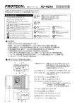
HD-SDI Multi-core Studio System
HD-SDI マルチコアケーブル スタジオシステム
Camera Adaptor
カメラアダプター
Base Station
ベースステーション
ES-300
ES-600
O perat ing I ns t ruc t ion s
取扱説明書
Before operating the system, please read this manual
thoroughly and remain it for future reference.
ご使用の前に、この取扱説明書をよくお読みください。
また、お読みになった後は、大切に保管してください。
Volume1, 1st edition Ver.1.0
安全上の注意
WARNING
この製 品の使用、または使用不 能から生ずる付随的な損害(情報内容の変化・消失、事業利益の損失、事業の
中断など)に関して、当社は責 任を負いかねますのであらかじめご了承ください。
取 扱 説 明 書の記 載内容を守らないこと、あるいは取扱説明書の記載内容の誤記、等により生じた損害に関して、
当社は責 任を負いかねますのであらかじめご了承ください。
ご使用の前に、この『 安 全 上の注 意 』をよくお読みのうえ、正しくお使いください。また、お読みになった後は、
大 切に保 管してください。
安 全 上の注 意は、お使いになる人や、他の人への危害、財産への損害を未然に防ぐための内容になっています
ので、必ずお守りください。
表示と図記号の意味は次のようになっています。
警告
取 扱いを誤った場 合 、使用者が死亡または重傷を負うことが想定されること を示します。
■煙が出ている、変なにおいや音がする等の異常が発生した場合は、電源スイッチを切る!
■本 機を落としたり、強い衝 撃を与えたり、破損した場合は、電源スイッチを切る!
■本 機の内部に水などが入った場 合は、電源スイッチを切る!
■本 機の内部に異 物などが入った場 合は、電源スイッチを切る!
※そのまま使用すると感 電・事 故を起こす恐れがあります。
お買い上げの販 売 店 または P ROTECHサービスセンターにご相談ください。
注意
取 扱いを誤った場 合 、使用者が傷害を負うことが想定されるか、または、物的損害の発生
が想 定されること
を示します。
■本 機の上に水の入った容 器 、小さな金属物を置かない!
禁止
こぼれて、本 機内部に入ると、発 熱や火 災 、感 電など、故 障や事 故を起こす恐れがあります。
■機 器の開口部から異 物を差し込んだり、落としこんだりしない!
禁止
発 熱や火 災 、感 電など、故 障や事 故を起こす原 因となります
■機 器が水 、汗 、海 水などの液 体で濡れたりしないようにする!
水ぬれ禁 止
発 熱や火 災 、感 電など、故 障や事 故を起こす原 因となります
雨 天 、降 雪中、海 岸 、水 辺でのご使用は特にご注 意ください。
■水などの液 体が使われたり、かかったりする場所で使用しない!
水場禁止
発 熱や火 災 、感 電など、故 障や事 故を起こす原 因となります
■本 機を分 解 , 改 造 , 修 理しない!
分解禁止
発 熱や火 災 、感 電など、故 障や事故を起こす原 因となります
点 検・整 備・修 理は、販 売 店またはP R O T E C Hサポートセンターにご依 頼ください。
2
Table of contents
Multi-core Studio System ES-300/ES-600
Names and Functions of Parts
ES-300/ES-600 目次
4
各部名称と働き
ES-300
Main panel
4
Front panel
5
メインパネル
フロントパネル
Rear panel
6
リアパネル
Connector panel
7
コネクタパネル
ES-600
Front panel
9
フロントパネル
Rear panel
11
リアパネル
LVM-89W / Universal Head
14
Connection
20
Adjustments and Settings
38
System Connection Guide
43
Outside View and Dimensions / Specifications
46
接続
調節・設定
システム構成例
外形寸法図・仕様
ES-300
46
ES-600
48
LVM-89W
50
03
Names and Functions of Parts
Camera Adaptor ES-300
ES-300 各部名称と働き
Main panel
メインパネル
INTERCOM
SIDE
TONE
CAMERA ADAPTOR
POWER switch and indicator
Turns the power on and off. The indicator lights up when the power switch is on.
電源をON/OFFするスイッチです。電源スイッチがONになっている時に点灯します。
TALLY indicator
Lights up when receiving the tally signal from the Base Station ES-600.
ベースステーションES-600からのタリー信号を受けて点灯します。
INTERCOM HEADSET Microphone, Headphone and Side tone volumes
Adjusts the audio levels of the microphone, the headphone and the side tone of the Intercom headset
DL-400 connected to the INTERCOM HEADSET connector (XLR 4-pin) on the connector panel.
コネクタパネルの INTERCOM HEADSETコネクタ(キャノン4P)に接続されたヘッドセットDL400の MIC,
H.P(ヘッドホン)およびサイドトーンの音量レベルを調整します。
MIC ON/OFF switch
Turns on/off the intercom headset microphone.
インターカムヘッドセットのマイクを ON/OFFします。
Tripod Adaptor plate
Fits with the Sony tripod base, VCT-14, VCT-U14.
三脚ベースSONY製VCT-14,VCT-U14に装着できます。
Tripod Screw and Pin
Fix to the bottom of the camcorder.
カムコーダーの底面へ取り付けます。
4
Camera Adaptor ES-300
ES-300 各部名称と働き
Front panel
フロントパネル
CAMERA ADAPTOR
TALLY OUT
DC 12VOUT
ES-300
RET OUT
(MAX3.0A)
DC12V OUT connector (XLR 4-pin, Female)
Outputs the DC12V power supplied from the Base Station ES-600 for a camera, a camera light, a monitor,
a prompter, etc. The maximum electric power is 30W.
ベースステーションES-600から供給されるDC12V電源を出力(キャノン4Pメス)します。カメラ、カムライト、LCDモニター
プロンプター等の電源に使用します。
MONITOR OUT connector
Connect to the Monitor LVW-89W with the 6-pin cable(VC-450).
The DC 12V power and tally signal are supplied to the Monitor LVM-89W.
モニター(LVM-89W)へ6ピンケーブルを使って接続します。DC 12V 電源および TALLY信号が LVM-89へ出力されます。
TALLY indicator and ON/OFF switch
Lights up when receiving the tally signal from the Base Station ES-600.
The indicator can be turned on and off with the TALLY ON/OF switch.
ベースステーションES-600からのタリー信号を受けて点灯します。
タリーON/OFFスイッチにより消灯させることができます。
TALLY OUT connector (BNC)
Outputs the TALLY signal from the Base Station ES-600.
ベースステーションES-600から送られるタリー信号を出力します。
RET OUT connector (BNC)
Outputs the return composite video signal from the Base Station ES-600.
ベースステーションES-600から送られるリターンビデオ信号を出力します。
5
Camera Adaptor ES-300
ES-300 各部名称と働き
Rear panel
リアパネル
AUDIO IN
TC OUT
MADE IN JAPAN
Audio IN connector(φ 3.5 stereo mini jack)
Input the audio signal from a camcorder.
カムコーダーからオーディオ信号を入力します。
TC OUT connector (BNC)
Outputs the time code signal from the Base Station ES-600. Connect to a camcorder with a BNC cable.
ES-600 からの TC( タイムコード ) 信号を出力します。
TALLY indicator and ON/OFF switch
Lights up when receiving the tally signal from the Base Station ES-600.
It doesn t light up when the TALLY ON /OFF switch is turned off.
ベースステーションES-600からタリー信号を受けて点灯します。タリー表示ON/OFFスイッチをOFFにすると消灯した
ままになります。
6
Camera Adaptor ES-300
ES-300 各部名称と働き
Connector panel
コネクタパネル
AUX
REMOTE
DC OUT
(VIDEO OUT/TC IN) VIDEO IN
INTERCOM
HEADSET
EXT.AUDIO OUT
Pr IN
Pb IN
Y IN
CAMERA connector (26-pin, male)
Connect to the Base Station ES-600 with a 26-pin multi-cable
(Sony CCZ-A25/50/100).
ベースステーションES-600と26ピンマルチケーブルにて接続します。
(SONY製CCZ-A25/50/100等)
26-pin connector
(male)
pin assignment
B
A
1
2
7
12
3
8
13
18
4
9
14
19
5
10
15
20
23
6
11
16
21
17
22
24
1
VIDEO OUT
14
REM POW
2
VIDEO SG
15
TALLY IN
3
Y SG
16
GEN IN G
4
Y OUT
17
REM VIDEO G
5
R-Y OUT
18
RET V IN
6
R-Y SG
19
RET V IN G
7
B-Y OUT
20
INCOM
8
B-Y SG
21
GEN IN X
9
MIC OUT
22
REM TX Y
10
MIC OUT
23
REM RX X
11
MIC OUT
24
REM RX Y
12
REM TX X
A
+12V
13
REM VIDEO X
B
GND
INTERCOM HEADSET connector (XLR 4-pin, Male)
Connect the Intercom headset DL-400. The audio level can be adjusted by the INTERCOM
volumes on the main panel.
インカムを使用する場合、
ヘッドセット (DL-400) を接続します。
音量は、メインパネルのボリュームで調節します。
In case using a headset with the XLR 4-pin male
connector, prepare the cable with the XLR 4-pin
female connectors.
1 MIC(G)
2 MIC(H)
3 H.PHONE(G)
キャノン4Pオスコネクタのヘッドセットを使用される場合は、
キャノン4Pメス-メスのケーブルをご用意下さい。
4 H.PHONE(H)
7
1
2
3
4
1
2
3
4
Camera Adaptor ES-300
ES-300 各部名称と働き
Connector panel
コネクタパネル
REMOTE connector (8-pin, female)
Outputs the 8-pin remote control signal to a camcorder. Connect with the 8-pin remote cable
(RCC-450).
8 ピンリモートコントロール信号をカムコーダーへ出力します。
RCC-450 で接続します。
LANC connector ( φ 2.5 mini-jack )
Outputs the LANC remote control signal to a camcorder. Connect with the LANC control cable.
LANCリモコンに対応するリモコン用φ2.5ジャックです。ランクコントロールケーブルでカムコーダーへ接続します。
DC OUT connector (4-pin)
Outputs the DC 8.4V power to a camcorder with the DC cable and
output the DC12V power to a wireless receiver.
ハンディカメラ用8.4Vおよびワイヤレス用12Vを出力します。
1
DC12V(G)
4
1
2
DC8.4V(G)
3
2
3
DC8.4V(+)
4
DC12V(+)
VIDEO IN connector (BNC)
Input the composite video signal from a camcorder with a BNC cable.
ビデオコンポジット信号を入力します。BNCケーブルでカムコーダーと接続します。
AUX (VIDEO OUT/TC IN) connector (BNC)
Outputs the video signal connected to the AUX (VIDEO IN) connector of the Base Station ES-600.
Or input the time code signal from a camcorder.
ベースステーションES-600のAUX(VIDEO IN)コネクタに接続されたビデオ信号を出力します。
あるいは、カムコーダーからTC信号を入力します。
Pr IN/Pb IN/Y IN connectors (BNC)
Input the analog component video signals from a camcorder with BNC cables.
アナログコンポーネント信号 (R-Y/B-Y/Y)を入力します。
EXT. AUDIO OUT connector (φ3.5 mini-jack)
Outputs the video signal connected to the EXT. AUDIO IN connector of the Base Station ES-600.
このコネクタはベースステーションの EXT. AUDIO IN コネクタと接続しています。
8
Names and Functions of Parts
Base Station ES-600
ES-600 各部名称と働き
Front panel
フロントパネル
ES-600
CABLE
100
EXT LINE (4W I/O)
INTERCOM
HEADSET
75
50
25
POWER switch and indicator
Turns the power on and off. The indicator lights up when the power switch is on.
電源をON/OFFするスイッチです。電源スイッチがONになっている時に点灯します。
TALLY indicator
Lights up when receiving the tally signal connected to the TALLY EXT LINE (4W I/O) IN connector
on the rear panel.
リアパネルのTALLY IN コネクタに入力されるタリー信号により点灯します。
TALLY SELECT switch
Select the TALLY channel and set the TALLY SELECT switch to the ON position to light up the TALLY
indicator.
タリーを点灯させるチャンネル(1 - 5 CH)のスイッチを選択して ON します。
CABLE select switch
Set to the appropriate position according to the length of a 26-pin multi-cable connected to the CAMERA
connector on the rear panel.
リアパネルのCAMERA 26-ピンケーブルコネクタに接続されたケーブル長に合わせて、ケーブル切替スイッチをセットします。
9
Base Station ES-600
ES-600 各部名称と働き
Front panel
フロントパネル
INTERCOM HEADSET connector (XLR 4-pin)
Connect the intercom headset(DL-400).
インカム ヘッドセット(DL-400)を接続します。
In case using the headset with the XLR 4-pin
male connector, prepare the cable with the
XLR 4-pin female connectors.
キャノン4Pオスコネクタのヘッドセットを使用される場合は、
キャノン4Pメス-メスのケーブルをご用意下さい。
1 MIC(G)
2 MIC(H)
1
2
3
4
1
2
3
4
3 H.PHONE(G)
4 H.PHONE(H)
INTERCOM HEADSET H.P(headphone), MIC(microphone) and SIDE TONE volumes
Adjusts the audio level of the headphone, microphone and side tone of the intercom headset connected
to the INTERCOM HEADSET connector. .
インカム ヘッドセット(DL-400)のヘッドホン、マイクロホン、サイドトーンの音声レベルを調整します。
INTERCOM EXT LINE (4W I/O) IN, OUT and SIDE TONE volumes
Adjusts the audio level of the input, output and side tone of the 4-wire intercom line connected to the
TALLY EXT LINE (4W I/O) IN/OUT connectors on the rear panel.
4W インターカムラインの入力、出力、サイドトーンの音声レベルを調整します。
10
Base Station ES-600
ES-600 各部名称と働き
Rear panel
リアパネル
HD/SD COMPONENT OUT
Y
Pb
SDI IN
OUT 1
CAMERA
VIDEO OUT
AUX
Pr
OUT 2
SDI RET IN OUT 1
AUDIO OUT
RET IN
VIDEO IN
LANC
TC OUT
OUT 2
EXT.
AUDIO IN
EXT LINE (2W I/O) EXT LINE (2W I/O)
TC IN
TALLY EXT LINE (4W I/O)
IN
OUT
AC IN
HD/SD COMPONENT OUT Y/Pb/Pr connectors (BNC)
Outputs the HD and SD analog component signal, Y, Pb and Pr from the Camera Adaptor ES-300.
カメラアダプタES-300からのHD / SD アナログコンポーネント信号( Y, Pb, Pr )を出力します。
VIDEO OUT connector (BNC)
Outputs the composite video signal from the Camera Adaptor ES-300.
カメラアダプタES-300からのコンポジットビデオ信号を出力します。
SDI IN connector (BNC)
Input the HD/SD-SDI signal from a camcorder.
カムコーダーからHD/SD-SDI 信号を入力します。
SDI OUT 1/2 connectors (BNC)
Outputs the HD/SD-SDI signal (through outputs of the SDI IN input signal).
HD/SD-SDI 信号を出力します。(SDI IN 入力信号のスルー出力)
SDI RET IN connector (BNC)
Input the HD/SD-SDI return signal from a switcher.
HD/SD-SDI リターン信号を入力します。
SDI RET OUT 1/2 connectors (BNC)
Outputs the HD/SD-SDI return signal (through outputs of the SDI RET IN input signal).
HD/SD-SDI リターン信号を出力します。(SDI RET IN 入力信号のスルー出力)
11
Base Station ES-600
ES-600 各部名称と働き
Rear panel
リアパネル
AUX connector (BNC) and VIDEO IN/TC OUT select switch
Input the composite video signal from an external vtdeo equipment or outputs the time cord signal from
the Camera Adaptor ES-300. Select the VIDEO IN or the TC OUT with the select switch.
ビデオコンポジット信号の入力またはES-300からのタイムコード信号の出力を切替スイッチで切り替えて使用します。
RET IN connector (BNC)
Input the composite video return signal from a switcher.
ビデオコンポジット リターン信号を入力します。
TC IN connector (BNC)
Input a time cord signal.
タイムコード信号を入力します。
CAMERA connector (26-pin, female)
Connect to the Camera Adaptor ES-300 with a 26-pin multi-cable (Sony CCZ-A25/50/100).
カメラアダプターES-300へ26ピンマルチケーブルにて接続します。(Sony CCZ-A25/50/100)
26-pin connector
(female)
pin assignment
B
6
17
22
11
16
5
10
21
24
4
15
20
23
9
14
19
A
3
8
13
18
2
7
1
12
1
VIDEO IN
14
REM POW(NC)
2
VIDEO SG
15
TALLY OUT
3
Y SG
16
GEN OUT G
4
Y IN
17
REM VIDEO G
5
R-Y IN
18
RET V OUT
6
R-Y SG
19
RET V OUT G
7
B-Y IN
20
INCOM
8
B-Y SG
21
GEN OUT X
9
MIC X
22
REM TX Y
10
MIC Y
23
REM RX X
11
MIC G
24
REM RX Y
12
RMT TXX
A
+12V
13
REM VIDEO X
B
GND
AUDIO OUT connector (XLR 3-pin, male)
Outputs the audio signal from the Camera Adaptor ES-300.
オーディオ信号を出力します。
Pin assignment XLR 3-pin,male
1PIN : GND
2PIN : HOT
3PIN : COLD
12
Base Station ES-600
ES-600 各部名称と働き
Rear panel
リアパネル
EXT LINE (2W I/O) connectors (XLR 3-pin, female and male)
Connect to an external 2-wire intercom line.
2Wインターカムラインに接続します。
Pin assignment
XLR 3-pin,female
2PIN : HOT
XLR 3-pin,male
2PIN : HOT
1PIN : GND
1PIN : GND
3PIN : COLD
3PIN : COLD
TALLY EXT LINE (4W I/O) IN/OUT connectors (D-sub 15-pin, female)
Used for the tally signal input/output and for the connection to an external 4-wire intercom line.
タリー信号の入出力、4Wインターカムラインへの接続に使用します。
D-sub 15-pin connector
(female)
pin assignment
5
4
10
15
3
9
14
2
8
13
1
7
12
6
11
1
TALLY 1
6
11
4W OUT H
2
TALLY 2
7
12
4W OUT L
3
TALLY 3
8
13
4W IN H
4
TALLY 4
9
14
4W IN L
5
TALLY 5
10
15
GND
GND
LANC connector (φ2.5 mini-jack)
Connect to an LANC remote controller by the cable supplied with the remote controller.
LANC リモコンに接続します。
REMOTE connector (8-pin)
Connect to the Sony remote controller RM-B750, B150 by the cable supplied with the remote controller.
Sony 製リモコン RM-B750,B150 にリモコン付属のケーブルで接続します。
AC IN connector
Connect to the AC 100V power supply with the supplied AC power cable.
AC 100V 電源に接続します。
FAN
Works when the POWER switch is on.
電源スイッチ on のとき動作します。
EXT. AUDIO IN connector (φ3.5 mini-jack)
Input an external audio signal. It can be output from the EXT. AUDIO OUT connector of the Camera
Adaptor DS-260.
外部オーディオ信号を入力します。この信号はカメラアダプタ DS-260 の EXT. AUDIO OUT コネクタから出力できます。
13
Names and Functions of Parts
LVM-89W 各部名称と働き
HDMI/HD Component Monitor LVM-89W/Universal Head
LVM-89W
Front Panel
HD/Y
HD/B-Y
HD/R-Y
CMP IN
CMP OUT
TALLY IN
MONI IF
PEAKING 16:9 MARKER RGB
4:3
COLOR INPUT
DC 12V IN
MONO
Connector Panel
(Right Side)
Left Side
Bottom Panel
Screen
8.9 inch liquid crystal display (196(H)
115(V) mm )
8.9インチ液晶(16:9)
The panel might be cracked and have no image when a load is added.
※パネルに負荷を加えると割れたり映らなくなります。
FRONT GREEN TALLY indicator
GREEN TALLY indicator on the front panel lights up when the tally signal(2∼4V=GREEN) is input
to the TALLY IN connector on the connector panel.
The brightness of the indicator can be selected by the FRONT TALLY display select switch.
グリーンタリーは、
コネクタパネルのTALLY IN コネクタに入力されるタリー信号(2∼4V=GREEN )により点灯します。
フロントパネルのフロントタリー切替スイッチ (OFF/L(low)/H(high))で明るさの切替えが可能です。
FRONT RED TALLY indicator
RED TALLY indicator on the front panel lights up when the tally signal(4∼ V=RED) is input to the
TALLY IN connector on the connector panel or the tally signal(0V=ON, OPEN=OFF) is input to the
MONI IF connector.
The brightness of the indicator can be selected by the FRONT TALLY display select switch.
レッドタリーは、
コネクタパネルのTALLY IN コネクタに入力されるタリー信号(4V以上=RED )により点灯します。
また、MONI IF コネクタに入力されるタリー信号(0V=ON)でも点灯します。
フロントパネルのフロントタリー切替スイッチ (OFF/L(low)/H(high))で明るさの切替えが可能です。
14
HDMI/HD Component Monitor LVM-89W/Universal Head
LVM-89W 各部名称と働き
LVM-89W
FRONT TALLY and REAR TALLY display select switch
The brightness of the TALLY indicators on the front and rear panels can be selected by the select
switches as follows.
H : The tally indicator lights up brightly.
L
: The tally indicator is dimmed to the lower brightness.
OFF : The tally indicator is turned off.
フロントタリー、
リアタリーの明るさの切替(OFF/L(low)/H(high))
スイッチです。
REAR GREEN TALLY indicator
GREEN TALLY indicator on the rear panel lights up when the tally signal(2∼4V=GREEN) is input
to the TALLY IN connector on the connector panel.
The brightness of the indicator can be selected by the REAR TALLY display select switch.
グリーンタリーは、
コネクタパネルのTALLY IN コネクタに入力されるタリー信号(2∼4V=GREEN ON)により点灯します。
フロントパネルのリアタリー切替スイッチ(OFF/L(low)/H(high))で明るさの切替えが可能です。
REAR RED TALLY indicator
RED TALLY indicator on the rear panel lights up when the tally signal(4∼ V=RED) is input to the
TALLY IN connector on the connector panel or the tally signal(0V=ON, OPEN=OFF) is input to the
MONI IF connector.
The brightness of the indicator can be selected by the REAR TALLY select switch.
レッドタリーは、
コネクタパネルのTALLY IN コネクタに入力されるタリー信号(4V以上=RED ON)により点灯します。
また、MONI IF コネクタに入力されるタリー信号(0V=ON)でも点灯します。
フロントパネルのリアタリー切替スイッチ(OFF/L(low)/H(high))で明るさの切替えが可能です。
MENU/ - / + buttons
MENU (select) button : selects the menu from the menus displayed
on the screen in sequence as follows.
- / + (entry) button : adjusts each setting value.
When the Reset menu is selected,
either pressing - or + button resets all
settings to the standard value(50).
MENU メニューボタンを順次押して、スクリーンに表示されるメニューから設定項目を選択して、- / + ボタンで調節します。
Resetを選択して - / + ボタンいずれかを押すとすべての設定値が標準値(50)にリセットされます。
15
HDMI/HD Component Monitor LVM-89W/Universal Head
LVM-89W各部名称と働き
LVM-89W
Function buttons
PEAKING 16:9 MARKER RGB
4:3
COLOR INPUT
MONO
INPUT select button : Select the input signal connected to the HD (Y/B-Y/R-Y) component, CMP IN
(composite signal input), and HDMI connector.
By pressing INPUT button, select the input mode in sequence. The selected
mode is displayed on the screen.
INPUT(入力セレクト)ボタンで、HD コンポーネントコネクタ、CMP IN コンポジット入力コネクタ, HDMI コネクタ に
接続された信号から入力する信号を選択します。INPUT ボタンを順次押して、選択します。
選択された入力モードが画面に表示されます。
INPUT select button
mode(in sequence)
signal
:
input connector
HD component : HD/Y, HD/B-Y, HD/R-Y(BNC) connector
CVBS 1
composite
← ← ← ← ←
COMP 1
COMP 2
NC
CVBS 2
NC
HDMI
HDMI
: CMP IN (BNC) connector
: HDMI connector
PEAKING button : By pressing PEAKING button select the peaking function ON or OFF.
The peaking level is adjustable by the MENU and -/+ button.
PEAKING(ピーキング) ボタンで ON/OFF します。ピーキングレベルはメニューで調節できます。
16:9 / 4:3 button : By pressing 16:9/4:3 button, select the frame size 16:9 or 4:3.
16:9 / 4:3 ボタンで フレームサイズの切替えができます。
MARKER button : By pressing Marker button select the marker in sequence as follows.
MARKER(マーカー) ボタンを押して順次マーカーサイズを切り替えます。
← ← ← ←← ←
no marker
16:9
16:9 with cross marker
4:3
4:3 with cross marker
all markers
RGB button : By pressing RGB button, select the image, the blue only, green only, or red only as follows.
RGB ボタンで BLUE ONLY, GREEN ONLY, RED ONLY の切替えが可能です。
← ← ←←
Full color
BLUE ONLY
GREEN ONLY
RED ONLY
COLOR/MONO button : By pressing COLOR/MONO button, select the image, the color or monochrome.
COLOR/MONO ボタンで カラー,モノクロの切替えが可能です。
16
HDMI/HD Component Monitor LVM-89W/Universal Head
LVM-89W各部名称と働き
LVM-89W
HD/Y, HD/B-Y, HD/R-Y connectors (BNC)
Input HD component signals. The input signals are displayed when the input select mode is set to the
COMP 1 mode.
HD コンポーネント(HD/Y, HD/B-Y, HD/R-Y)信号を入力します。INPUT 切替ボタンをCOMP 1 に切り替えて表示します。
CMP IN connector (BNC)
Input a composite video signal. The input signal is displayed when the input select mode is set to the
CVBS 1 mode.
コンポジットビデオ信号を入力します。INPUT 切替ボタンをCVBS 1 に切り替えて表示します。
In order to monitor the return video signal(composite) from the camera adaptor, connect the signal
to this connector with BNC cable.
※カメラアダプターからのリターン信号(コンポジット)をモニターする場合は、リターン信号をこのコネクタに接続
します。
CMP OUT connector (BNC)
Outputs the composite video signal. (Through output of the CMP IN input signal)
CMP IN コネクタに入力されたコンポジットビデオ信号をスルーで出力します。
TALLY IN connector (BNC)
Input the tally signal( O∼2V=OFF, 2∼4V=GREEN, 4∼ V=RED ).
タリー信号を入力します。タリー信号の電圧により、2∼4VのときGREEN, 4V以上のときREDが点灯します。
MONI IF connector (6-pin, female)
The DC 12V power and the tally signal are supplied from the Camera Adaptor via the 6-pin cable(VC-450).
カメラアダプタから6ピンケーブルを通して、12V電源、タリー信号が入力されます。
MONI IF connector
(6-pin, female)
Pin assignment
For the use of the designated 6-pin cable only.
※専用6ピンケーブルのみ使用可能です。
1
GND
2 +12V IN
3
4
5
6
17
約650mA
SG
NC
TALLY IN
NC
0V=ON
HDMI/HD Component Monitor LVM-89W/Universal Head
LVM-89W各部名称と働き
LVM-89W
DC 12V IN connector (XLR 4-pin)
Connect an external DC 12V power. ( 10∼16V )
DC 12V 電源( 10∼16V, AC アダプタ等)を接続します。
HDMI connector
Input a HDMI signal with HDMI cable. The input signal is displayed when the input select mode is set
to the HDMI mode.
HDMI ケーブルでHDMI信号を入力します。
これは、INPUTボタンで HDMI に切り替えて表示します。
1/4 inch screw hole
Fix the universal head.
ユニバーサルヘッドを取り付けます。
18
HDMI/HD Component Monitor LVM-89W/Universal Head
LVM-89W各部名称と働き
Universal Head
Monitor lock screw(1/4 inch)
モニター固定ネジ
Used to fix the monitor.
モニターを固定します。
Angle adjustment knob
角度調節ノブ
Used to adjust the monitor position to any angle so that the display can be watch well.
モニターの画面を見やすい角度に調節し、固定します。
Slide-shoe lock knob
スライドシュー固定ノブ
Used to fix the Slide Shoe to a camera accessory shoe.
モニターのスライドシューをカメラのアクセサリーシューに固定します。
Slide-shoe
スライドシュー
Slide into a camera accessory shoe.
カメラのアクセサリーシューに挿入します。
1/4 inch screw hole (female)
1/4インチネジ穴
Used to be fitted up with a 1/4 inch camera screw (male).
When mounted on the camera with the 1/4 inch screw hole(female) install supplied 1/4 inch
male-male screw adaptpr and fitted up with the camera.
1/4インチカメラネジへ取り付けるネジ穴です。
カメラが1/4インチネジ穴の場合、1/4インチオス-オスネジアダプタ(
1/4 inch male-male screw adaptor
)を取り付けてカメラに固定します。
1/4インチオス-オスネジアダプタ
Used to mount the universal head on the camera with the 1/4 inch screw hole(female).
ユニバーサルヘッド(メスネジ)をカメラ等の1/4インチネジ穴へ取り付ける場合に使用します。
19
Connection
Multi-core Studio System ES-300/ES-600
ES-300/ES-600 接続方法
Make sure to turn off the POWER switch of each unit before connecting.
接続する前に必ず各機器の電源スイッチを OFFにしてください。
Mount on the tripod
1
三脚への取り付け
Fix the camera adaptor ES-300 tightly to the bottom surface of a camcorder with the camera screw(s).
カムコーダー の底面にカメラアダプターES-300 をカメラネジでしっかり取りつけます。
ES-300
INTERCOM
SIDE
TONE
CAMERA ADAPTOR
In case of a camcorder which has one screw hole with the guide
pin hole.
ガイドピン穴と取り付け穴が一つのカムコーダーの場合
guide pin
Take off the auxiliary camera screw and fix the adaptor into the
screw hole of a camcorder with the main camera screw along
the guide pin.
補助ネジを取り外し、ガイドピンに沿ってカメラネジを取りつけます。
In case of a camcorder which has 2 screw holes such as
Sony PMW-EX3.
ソニーPMW-EX3のように取りつけネジ穴が二つあるカムコーダーの場合
Take off the guide pin and fix the adaptor into the screw holes
with the two camera screws.
to camcorder
INTERCOM
SIDE
TONE
CAMERA ADAPTOR
take off
auxiliary screw
(W1/4 camera screw)
main screw
(W1/4 camera screw)
(ex. Sony PMW-EX3)
take off
the guide pin
to camcorder
INTERCOM
SIDE
TONE
CAMERA ADAPTOR
ガイドピンを取り外し二本のカメラネジを取りつけます。
W1/4 camera screws
2
Mount the camcorder with ES-300 on a tripod.
三脚に装着します。
20
Multi-core Studio System ES-300/ES-600
ES-300/ES-600 接続方法
Fix the monitor LVM-89W
1
LVM-89Wモニターの取り付け
Fix the supplied universal head to the screw hole on the bottom surface of LVM-89W with the Monitor
Lock Screw.
LVM-89W底部の1/4インチ固定ネジ穴にユニバーサルヘッドをモニター固定ネジで固定します。
Bottom Panel
Monitor Lock Screw
Universal head
2
Slide the universal head with LVM-89W into the accessory shoe of the camcorder untill the slide-shoe
stops in place. Tighten the Slide-Shoe Lock Knob to fix the universal head with the accessory shoe.
Loosen the Angle Adjustment Knob and adjust the angle of LVM-89W so that the monitor can be watched
well, then tighten the knob again.
カメラのアクセサリーシューの止まる位置までスライドさせます。
シューから抜けないようにシュー固定ねじで固定します。
角度調整固定ねじを緩めてモニターの見やすい位置が決まった後、再度固定ねじを締めます。
Angle Adjustment Knob
Slide-Shoe Lock Knob
MENU
-
REAKING 16:9 MARKER
FRONT TALLY REAR TALLY
+
OFF L H
4:3
OFF L H
RGB COLOR INPUT
MONO
Slide-Shoe
Accessory Shoe
2-2
To mount LVM-89W to the camera with the 1/4 inch screw hole(female) install the 1/4 inch male-male
screw adaptor to the bottom of the universal head and screw up to the screw hole of the camera.
1/4インチネジ穴タイプのカメラの場合は、
ユニバーサルヘッドの下にオス-オスネジアダプタを取り付けて使用します。
MENU
-
+
FRONT TALLY REAR TALLY
OFF L H
Male-male
Screw
Adaptor
OFF L H
REAKING 16:9 MARKER
4:3
RGB COLOR INPUT
MONO
Male-male
Screw
Adaptor
21
Multi-core Studio System ES-300/ES-600
ES-300/ES-600 接続方法
LVM-89W connection
LVM-89Wの接続方法
Monitoring the video signal
1
Connect an external DC 12V power supply with a XLR 4-pin cable.
Or connect the MONI IF connector to the MONITOR OUT connector of the Camera Adaptor with the
6-pin cable(VC-450).
DC 12V IN コネクタへ DC 12V 電源をキャノン4ピンケーブルで接続します。
またはMONI IFコネクタへカメラアダプタから6ピンケーブル(VC-450)を接続します。
2
Connect the input signal to the appropriate connector according to the video signal from a camcorder.
And select the input mode by the INPUT select button.
カムコーダーから入力するビデオ信号に合わせて各コネクタに接続します。INPUT 切替スイッチを入力信号に合わせます。
Set the INPUT select switch
(Connector)
(Input mode)
HDMI connector (Rear panel)
HDMI
HD component connectors
HD/Y
HD/B-Y
HD/R-Y
(BNC 3)
COMP 1
CMP IN connector
(BNC)
CVBS 1
MONI IF connector(6-pin)
( DC 12V, TALLY signal )
DC 12V IN connector
LVM-89W
(Connector)
connect to
(HD-Y return output)
INPUT select mode
(displayed on the screen)
HD/Y
(HD component output)
COMP 1
HD/B-Y
HD/R-Y
(Composite video input)
CMP OUT
(TALLY output)
Camera adaptor
ES-300/ES-500
( DC 12V, TALLY signal )
TALLY IN
MONI IF
(6-pin cable)
DC 12V power supply
(AC adaptor)
(HDMI output)
CVBS 1
CMP IN
(Composite video output)
DC 12V IN
(Rear)
HDMI
22
HDMI
Multi-core Studio System ES-300/ES-600
ES-300/ES-600 接続方法
26-pin multi-cable connection
1
26ピンカメラケーブルの接続
Connect both the CAMERA connectors of the Camera Adaptor and the Base Statioin with a 26-pin multi-cable.
26 ピンケーブルでカメラアダプタとベースステーションとを接続します。
(connector panel)
(rear)
AUX
AUDIO IN
TC OUT
DC OUT
REMOTE
(VIDEO OUT/TC IN) VIDEO IN
INTERCOM
HEADSET
MADE IN JAPAN
EXT.AUDIO OUT
Pr IN
Pb IN
Y IN
(26-pin)
(26-pin)
ES-300
CAMERA connector(26-pin)
ES-600
HD/SD COMPONENT OUT
Y
Pb
SDI IN
OUT 1
CAMERA
VIDEO OUT
AUX
Pr
SDI RET IN OUT 1
OUT 2
AUDIO OUT
RET IN
VIDEO IN
LANC
TC OUT
OUT 2
EXT.
AUDIO IN
EXT LINE (2W I/O) EXT LINE (2W I/O)
TC IN
TALLY EXT LINE (4W I/O)
IN
OUT
AC IN
(26-pin)
ES-600
CABLE
100
EXT LINE (4W I/O)
INTERCOM
HEADSET
75
50
25
CABLE select switch
2
Set the CABLE select switch to the appropriate position according to the length of the 26-pin multi-cable
connected to the CAMERA connector.
接続された 26 ピンケーブルの長さに合わせて CABLE/25/50/75/100 ケーブル切替スイッチをセットします。
23
Multi-core Studio System ES-300/ES-600
ES-300/ES-600 接続方法
HD/SD component video signals connection
1
HD/SDコンポーネント信号の接続
Connect the HD/SD component video output signals from a camcorder to the Y IN/Pb IN/Pr IN connectors of
ES-300 with BNC cables.
カムコーダーからの HD/SD コンポーネント信号出力は、Y IN/ Pb IN/Pr IN コネクタへ BNC ケーブルで接続します。
HD/SD component video signals
from
camcorder
ES-300
AUX
DC OUT
REMOTE
(VIDEO OUT/TC IN) VIDEO IN
INTERCOM
HEADSET
EXT.AUDIO OUT
Pr IN
Pb IN
Y IN
Pr IN Pb IN Y IN
(26-pin cable)
HD/SD component video signals
Y
Pr
Pb
HD/SD COMPONENT OUT
Y
Pb
SDI IN
OUT 1
CAMERA
to
switcher,
VTR,
monitor,
etc.
VIDEO OUT
AUX
Pr
OUT 2
SDI RET IN OUT 1
AUDIO OUT
RET IN
VIDEO IN
LANC
TC OUT
OUT 2
EXT.
AUDIO IN
EXT LINE (2W I/O) EXT LINE (2W I/O)
TC IN
TALLY EXT LINE (4W I/O)
IN
OUT
AC IN
ES-600
2
Connect the HD/SD COMPONENT OUT (Y/Pb/Pr) connectors of ES-600 to a switcher, a VTR, a monitor,
etc. with BNC cables.
ベースステーションの HD/SD COMPONENT OUT Y/Pb/Pr コネクタからスイッチャー、VTR、モニター等へBNC
ケーブルで接続します。
24
Multi-core Studio System ES-300/ES-600
ES-300/ES-600 接続方法
Composite video signal connection
1
コンポジットビデオ信号の接続
Connect the composite video output signal from a camcorder to the VIDEO IN connector with a BNC cable.
カムコーダーのコンポジットビデオ信号出力は、VIDEO IN コネクタへ BNCケーブルで接続します。
Composite video signal
from
camcorder
ES-300
VIDEO IN
AUX
DC OUT
REMOTE
(VIDEO OUT/TC IN) VIDEO IN
INTERCOM
HEADSET
EXT.AUDIO OUT
Pr IN
Pb IN
Y IN
(26-pin cable)
Composite video signal
to
switcher,
VTR,
monitor,
etc.
ES-600
HD/SD COMPONENT OUT
Y
Pb
SDI IN
OUT 1
CAMERA
2
VIDEO OUT
AUX
Pr
OUT 2
SDI RET IN OUT 1
AUDIO OUT
RET IN
VIDEO IN
LANC
TC OUT
OUT 2
EXT.
AUDIO IN
EXT LINE (2W I/O) EXT LINE (2W I/O)
TC IN
TALLY EXT LINE (4W I/O)
IN
OUT
AC IN
Connect the VIDEO OUT connector to a switcher, a VTR, a monitor, etc. with a BNC cable.
コンポジットビデオ信号は、VIDEO OUT コネクタからスイッチャー、レコーダー、モニター等へ BNCケーブルで接続
します。
25
Multi-core Studio System ES-300/ES-600
ES-300/ES-600 接続方法
Return composite video signal connection
リターンコンポジットビデオ信号の接続
1
Connect the RET OUT connector to a monitor, etc. with a BNC cable.
リターンコンポジットビデオ信号の出力は、RET OUT コネクタからモニター等へ BNC ケーブルで接続します。
return
composite
video signal
to
monitor,
etc.
RET OUT
(BNC)
(front)
CAMERA ADAPTOR
TALLY OUT
DC 12VOUT
ES-300
RET OUT
(MAX3.0A)
ES-300
AUX
REMOTE
DC OUT
(VIDEO OUT/TC IN) VIDEO IN
INTERCOM
HEADSET
EXT.AUDIO OUT
Pr IN
Pb IN
Y IN
return
composite
video signal
RET IN
(BNC)
ES-600
HD/SD COMPONENT OUT
Y
Pb
SDI IN
OUT 1
CAMERA
2
VIDEO OUT
AUX
Pr
OUT 2
SDI RET IN OUT 1
AUDIO OUT
RET IN
VIDEO IN
LANC
TC OUT
OUT 2
EXT.
AUDIO IN
EXT LINE (2W I/O) EXT LINE (2W I/O)
from
switcher,
etc.
TC IN
TALLY EXT LINE (4W I/O)
IN
OUT
AC IN
Connect the return composite video output signal from a switcher to the RET IN connector with a BNC cable.
スイッチャー出力のリターンコンポジットビデオ信号は、RET IN コネクタへ BNC ケーブルで接続します。
26
Multi-core Studio System ES-300/ES-600
ES-300/ES-600 接続方法
Return composite video signal connection with LVM-89W
1
リターンコンポジットビデオ信号/LVM-89Wの接続
Connect the RET OUT connector of the camera adaptor ES-300 to the CMP IN (composite signal input)
connector of the monitor LVM-89W with a BNC cable.
リターン画 ( リターンコンポジットビデオ信号 ) を LVM-89W に映す場合は、ES-300 の RET OUT と VM-89W の CMP IN
とを BNC ケーブルで接続します。
To supply the DC 12V power, connect the MONITOR OUT connector of camera adaptor and the MONITOR
IF connector of the monitor with the 6-pin cable (VC-450).
Or connect the DC 12V OUT connector of the camera adaptor and the DC 12V IN connector of the monitor
with a XLR 4-pin cable.
電源は、LVM-89W の MONITOR IF コネクタへ ES-300 の MONITOR OUT コネクタから 6 ピンケーブルで接続します。
または LVM-89W の DC 12V IN コネクタへ ES-300 の DC 12V OUT からキャノン 4 ピンケーブルで接続します。
HD/Y
return
composite
video signal
HD/B-Y
HD/R-Y
CMP IN
CMP IN
CMP OUT
MONI IF
MONI IF
PEAKING 16:9 MARKER RGB
4:3
COLOR INPUT
DC 12V IN
MONO
DC 12V IN
(DC power)
LVM-89W
ES-300
front panel
BNC cable
DC power,and
TALLY signal
6-pin cable (VC-450)
TALLY IN
XLR 4-pin cable
2
RET OUT
(BNC)
AUX
CAMERA ADAPTOR
REMOTE
DC OUT
TALLY OUT
(VIDEO OUT/TC IN) VIDEO IN
INTERCOM
HEADSET
DC 12VOUT
EXT.AUDIO OUT
Pr IN
26
Pb IN
ES-300
RET OUT
(MAX3.0A)
Y IN
cab
-pin
le
DC 12V OUT
(XLR 4-pin)
MONITOR OUT
(6-pin)
return
composite
video signal
RET IN
(BNC)
ES-600
HD/SD COMPONENT OUT
Y
Pb
SDI IN
from
switcher,
etc.
OUT 1
CAMERA
VIDEO OUT
AUX
Pr
OUT 2
SDI RET IN OUT 1
AUDIO OUT
RET IN
VIDEO IN
LANC
TC OUT
OUT 2
EXT.
AUDIO IN
EXT LINE (2W I/O) EXT LINE (2W I/O)
27
TC IN
TALLY EXT LINE (4W I/O)
IN
OUT
AC IN
Multi-core Studio System ES-300/ES-600
ES-300/ES-600 接続方法
AUX composite video signal connection
1
AUXコンポジットビデオ信号の接続
Connect the AUX (VIDEO OUT/TC IN) connector to a prompter, etc. with a BNC cable.
(NOTE : Set the VIDEO IN/TC OUT select switch of the base station ES-600 to VIDEO IN position.)
ビデオコンポジット信号を出力する場合は、AUX (VIDEO OUT) コネクタへ BNC ケーブルで接続します。
( 注 : ベースステーション ES-600 の VIDEO IN/TC OUT 切替スイッチを VIDEO IN にセットします。)
to
camcorder
composite video signal
GENLOCK signal
to
prompter,
etc.
AUX
(VIDEO OUT/TC IN)
ES-300
AUX
REMOTE
DC OUT
(VIDEO OUT/TC IN) VIDEO IN
INTERCOM
HEADSET
Pr IN
EXT.AUDIO OUT
Pb IN
Y IN
composite video signal
GENLOCK signal
from
GENLOCK signal
generator
Select switch is set to VIDEO IN position.
HD/SD COMPONENT OUT
ES-600
Y
Pb
SDI IN
OUT 1
CAMERA
2
from
video equipment
VIDEO OUT
AUX
Pr
OUT 2
SDI RET IN OUT 1
AUDIO OUT
RET IN
VIDEO IN
LANC
TC OUT
OUT 2
EXT.
AUDIO IN
EXT LINE (2W I/O) EXT LINE (2W I/O)
TC IN
TALLY EXT LINE (4W I/O)
IN
OUT
AC IN
Connect a commposite video output signal from an external video equipment to the AUX connector with
a BNC cable and set the VIDEO IN/TC OUT select switch to the VIDEO IN position.
外部ビデオ機器からのコンポジットビデオ信号は、AUX コネクタへ BNC ケーブルで接続し、VIDEO IN/TC OUT 切替スイッチ
を VIDEO IN にセットします。
In case of using the GENLOCK signal :
Connect a GENLOCK signal from an external GENLOCK signal generator to the AUX connector of
ES-600 with a BNC cable and set the VIDEO IN/TC OUT select switch to the VIDEO IN position.
And connect the AUX (VIDEO OUT/TC IN) connector of ES-300 to a camcorder with a BNC cable.
GENLOCK 信号を使用する場合は、ES-600 の AUX コネクタへ BNC ケーブルで接続し、切替スイッチを VIDEO IN に
セットします。
GENLOCK 信号の出力は、ES-300 の AUX (VIDEO OUT/TC IN) からカムコーダーへ BNC ケーブルで接続します。
28
Multi-core Studio System ES-300/ES-600
ES-300/ES-600 接続方法
Time code signal connection
TC信号の接続
Time code signal to a camcorder :
1
Connect the TC OUT connector of ES-300 to a camcorder with a BNC cable.
TC 信号を出力する場合は、ES-300 の TC OUT コネクタからカムコーダーへ BNC ケーブルで接続します。
2
Connect the time code output signal from a time code signal generator to the TC IN connector of ES-600
with a BNC cable.
TC IN コネクタへ TC 信号発生器から BNC ケーブルで接続します。
TC signal
to
camcorder
TC OUT
from
Time code signal
generator
TC signal
AUDIO IN
TC OUT
MADE IN JAPAN
ES-600
ES-300
HD/SD COMPONENT OUT
Y
Pb
SDI IN
VIDEO OUT
AUX
Pr
OUT 1
OUT 2
CAMERA
SDI RET IN OUT 1
AUDIO OUT
RET IN
VIDEO IN
LANC
EXT.
AUDIO IN
TC OUT
OUT 2
EXT LINE (2W I/O) EXT LINE (2W I/O)
TC IN
TALLY EXT LINE (4W I/O)
OUT
IN
AC IN
Time code signal from a camcorder :
1
Connect the time code output signal from a camcorder to the AUX connector of ES-300 with a BNC cable.
TC 信号をカムコーダーから入力する場合は、ES-300 の AUX コネクタへカムコーダーから BNC ケーブルで接続します。
2
Connect the AUX connector of ES-600 to an external video equipment with a BNC cable and set the
VIDEO IN/TC OUT select switch to the TC OUT position.
TC 信号を出力する場合は、ES-600 の AUX コネクタから外部ビデオ機器へ BNC ケーブルで接続し、VIDEO IN/TC OUT
切替スイッチを TC OUT にセットします。
TC signal
from
camcorder
AUX
(VIDEO OUT/TC IN)
TC signal
to external
video equipment
AUX
REMOTE
DC OUT
(VIDEO OUT/TC IN) VIDEO IN
INTERCOM
HEADSET
EXT.AUDIO OUT
Pr IN
Pb IN
Y IN
Select switch is set to
TC OUT position.
ES-300
HD/SD COMPONENT OUT
ES-600
Y
Pb
SDI IN
OUT 1
CAMERA
29
VIDEO OUT
AUX
Pr
OUT 2
SDI RET IN OUT 1
AUDIO OUT
RET IN
VIDEO IN
LANC
TC OUT
OUT 2
EXT.
AUDIO IN
EXT LINE (2W I/O) EXT LINE (2W I/O)
TC IN
TALLY EXT LINE (4W I/O)
IN
OUT
AC IN
Multi-core Studio System ES-300/ES-600
ES-300/ES-600 接続方法
HD/SD SDI video signal connection
HD/SD SDIビデオ信号の接続
1 HD/SD SDI signal :
Connect the HD/SD SDI output signal from a camcorder to the SDI IN connector of ES-600 with a BNC cable.
And connect the SDI OUT1/2 connectors to a switcher, a monitor, a VTR, etc. with a BNC cable.
カムコーダーの HD/SD SDI 信号出力は、ES-600 の (HD/SD)SDI IN コネクタへ、BNC ケーブルで接続します。
ES-600 の (SDI) OUT1/2 から、モニター、スイッチャー、モニター、VTR, 等へ BNC ケーブルで接続します。
HD/SD SDI
monitor
HD/SD SDI input
DC 12V input (XLR 4-pin)
*
(BNC)
2
HD/SD SDI
return signal
Camcorder
(BNC)
1
DC 12V power
HD/SD SDI output
HD/SD SDI signal
AUX
(VIDEO OUT/TC IN) VIDEO IN
DC OUT
REMOTE
DC 12V OUT
(XLR 4-pin)
INTERCOM
HEADSET
ES-300
Pr IN
EXT.AUDIO OUT
Pb IN
Y IN
(26-pin)
(ES cable)
1
to
switcher,
monitor,
VTR, etc.
HD/SD SDI signal
SDI OUT
SDI RET OUT
HD/SD COMPONENT OUT
Y
Pb
SDI IN
SDI IN
OUT 1
CAMERA
ES-600
VIDEO OUT
AUX
Pr
OUT 2
SDI RET IN OUT 1
AUDIO OUT
RET IN
VIDEO IN
LANC
TC OUT
OUT 2
EXT.
AUDIO IN
EXT LINE (2W I/O) EXT LINE (2W I/O)
TC IN
TALLY EXT LINE (4W I/O)
IN
OUT
AC IN
SDI RET IN
2
HD/SD SDI
return signal
from
switcher,
etc.
2 HD/SD SDI return signal :
Connect the HD/SD SDI return output signal from a switcher to the SDI RET IN connector with a BNC cable.
And connect the SDI RET OUT1 or 2 connector to a HD/SD SDI monitor with a BNC cable.
スイッチャーからの HD/SD SDI リターン信号出力は、SDI RET IN コネクタに BNC ケーブルで接続します。
SDI RET OUT1/2 コネクタから SDI モニター等へ BNC ケーブルで接続します。
*
DC 12V power for a HD/SD SDI monitor can be supplied from the DC 12V OUT connector of ES-300
with a XLR 4-pin cable.
モニターの DC 12V 電源は、ES-300 フロントパネルの DC12V OUT コネクタからキャノン 4 ピンケーブルで供給できます。
30
Multi-core Studio System ES-300/ES-600
ES-300/ES-600 接続方法
AUDIO signal connection
1
オーディオ信号の接続
Connect the audio output signal from a camcorder to the AUDIO IN connector,φ3.5 stereo mini jack, with
an audio cable.
オーディオ 信号を入力する場合は、AUDIO IN コネクタ (φ3.5 ミニジャック ) へ接続します。
(rear)
audio signal
from
camcorder
AUDIO IN
(φ3.5 mini jack)
ES-300
TC OUT
MADE IN JAPAN
in
(26-p
)
cable
ES-600
HD/SD COMPONENT OUT
Y
Pb
SDI IN
AUX
Pr
OUT 1
CAMERA
VIDEO OUT
OUT 2
SDI RET IN OUT 1
AUDIO OUT
RET IN
VIDEO IN
LANC
TC OUT
OUT 2
EXT.
AUDIO IN
EXT LINE (2W I/O) EXT LINE (2W I/O)
TC IN
TALLY EXT LINE (4W I/O)
IN
(XLR 3-pin)
audio signal
2
OUT
AC IN
to
switcher,
VTR,
audio mixer,
etc.
Connect the AUDIO OUT connector to a switcher, a VTR, an audio mixer, etc. with a XLR 3-pin cable.
オーディオ信号の出力は、AUDIO OUT コネクタからキャノン 3 ピンケーブルでスイッチャー、VTR、オーディオミキサー
等へ接続します。
31
Multi-core Studio System ES-300/ES-600
ES-300/ES-600 接続方法
INTERCOM HEADSET connection
1
インターカムヘッドセットの接続
ES-300 :
Connect the headset DL-400 to the INTERCOM HEADSET connector(XLR 4-pin, male) on the
connector panel.
ヘッドセット DL-400 を INTERCOM HEADSET コネクタ ( キャノン 4 ピン , オス ) へ接続します。
ES-300
AUX
DC OUT
REMOTE
(VIDEO OUT/TC IN) VIDEO IN
INTERCOM
HEADSET
EXT.AUDIO OUT
Pr IN
Pb IN
Y IN
DL-400
2
ES-600 :
Connect the headset DL-400 to the INTERCOM HEADSET connector (XLR 4-pin, male) on the
front panel.
ヘッドセット DL-400 を INTERCOM HEADSET コネクタ ( キャノン 4 ピン , オス ) へ接続します。
ES-600
ES-600
CABLE
100
EXT LINE (4W I/O)
HEADSET
INTERCOM
75
50
DL-400
25
In case using a headset with the XLR 4-pin
male connector, prepare the cable with the
XLR 4-pin female connectors.
キャノン4P オスコネクタのヘッドセットを使用される場合
は、キャノン4P メス-メスのケーブルをご用意下さい。
1 MIC(G)
2 MIC(H)
3 H.PHONE(G)
4 H.PHONE(H)
32
1
2
3
4
1
2
3
4
Multi-core Studio System ES-300/ES-600
ES-300/ES-600 接続方法
INTERCOM 2W line/4W line connection
インターカムの接続
1 INTERCOM 2W line :
Connect the EXT LINE (2W I/O) connectors (XLR 3-pin, female and male) to an external intercom 2W line
with a XLR 3-pin cable.
インターカム 2W ラインに接続する場合は、EXT LINE (2W I/O) コネクタにキャノン 3P ケーブルで接続します。
ES-600
HD/SD COMPONENT OUT
Y
Pb
SDI IN
OUT 1
VIDEO OUT
AUX
Pr
OUT 2
CAMERA
SDI RET IN OUT 1
AUDIO OUT
RET IN
VIDEO IN
LANC
TC OUT
OUT 2
EXT.
AUDIO IN
EXT LINE (2W I/O) EXT LINE (2W I/O)
TC IN
TALLY EXT LINE (4W I/O)
OUT
IN
AC IN
INTERCOM 2-wire line
2 INTERCOM 4W line :
Connect the TALLY EXT LINE (4W I/O) IN/OUT connectors (D-sub 15-pin, female) to the an external
intercom 4W line with a D-sub 15-pin cable.
インターカム 4W ラインに接続する場合は、TALLY EXT LINE (4W I/O) IN/OUT コネクタ (D-sub 15-pin) に接続します。
ES-600
HD/SD COMPONENT OUT
Y
Pb
SDI IN
OUT 1
CAMERA
VIDEO OUT
AUX
Pr
OUT 2
SDI RET IN OUT 1
AUDIO OUT
RET IN
VIDEO IN
LANC
TC OUT
OUT 2
EXT.
AUDIO IN
EXT LINE (2W I/O) EXT LINE (2W I/O)
TC IN
TALLY EXT LINE (4W I/O)
IN
OUT
AC IN
INTERCOM 4-wire line
33
Multi-core Studio System ES-300/ES-600
ES-300/ES-600 接続方法
TALLY signal connection
1
タリー信号の接続
Connect the TALLY OUT connector of the camera adaptor ES-300 to a monitor with a BNC cable.
タリー信号を出力する場合は、TALLY OUT コネクタからモニターへ BNC ケーブルで接続します。
ES-300
CAMERA ADAPTOR
TALLY OUT
DC 12VOUT
ES-300
TALLY OUT
RET OUT
to monitor
(MAX3.0A)
TALLY signal
from
switcher,
etc.
TALLY signal
TALLY signal
to
the next
base station
ES-600
HD/SD COMPONENT OUT
Y
Pb
SDI IN
OUT 1
CAMERA
2
VIDEO OUT
AUX
Pr
OUT 2
SDI RET IN OUT 1
AUDIO OUT
RET IN
VIDEO IN
LANC
EXT.
AUDIO IN
TC OUT
OUT 2
EXT LINE (2W I/O) EXT LINE (2W I/O)
TC IN
TALLY EXT LINE (4W I/O)
IN
OUT
AC IN
Connect the tally signal from a switcher to the TALLY EXT LINE (4W I/O) IN connector with the D-sub
15-pin cable.
Connect the TALLY EXT LINE (4W I/O) OUT connector to the next base station ES-600 with the D-sub
15-pin cable.
スイッチャーからのタリー信号は、TALLY EXT LINE (4W I/O) IN コネクタへ D-sub15 ピンケーブルで接続します。
次の ES-600 へタリー信号を出力する場合は、TALLY EXT LINE(4W I/O) OUT コネクタから D-sub15 ピンケーブルで接続
します。
34
Multi-core Studio System ES-300/ES-600
ES-300/ES-600 接続方法
REMOTE controller connection
リモコンの接続
In case of using a 8-pin remote controller (Sony RM-B750,B150, etc.) :
1
Connect a 8-pin remote controller (Sony RM-B150, B750, etc.) to the REMOTE connector of ES-600(rear
panel) by the supplied cable with a remote controller.
8 ピン リモコン ( Sony 製 RM-B150, B750 等 ) を接続して使用する場合は、ES-600 リアパネルの REMOTE コネクタへ
リモコン付属のケーブルで接続します。
2
Connect the REMOTE connector of ES-300 and the remote connector of a camcorder with the 8-pin cable
(RCC-450).
ES-300 の REMOTE コネクタからカムコーダーへ、8 ピンケーブル (RCC-450) で接続します。
8-pin cable(RCC-450)
to
camcorder
to
8-pin remote controller
ES-300
AUX
REMOTE
DC OUT
(VIDEO OUT/TC IN) VIDEO IN
INTERCOM
HEADSET
EXT.AUDIO OUT
Pr IN
Pb IN
Y IN
ES-600
HD/SD COMPONENT OUT
Y
Pb
SDI IN
VIDEO OUT
AUX
Pr
OUT 1
OUT 2
CAMERA
SDI RET IN OUT 1
AUDIO OUT
RET IN
VIDEO IN
LANC
TC OUT
OUT 2
EXT.
AUDIO IN
EXT LINE (2W I/O) EXT LINE (2W I/O)
TC IN
TALLY EXT LINE (4W I/O)
OUT
IN
AC IN
In case of using a LANC remote controller :
1
Connect a LANC remote controller to the LANC connector of ES-600(rear panel) by the supplied cable
with a remote controller.
LANC リモコンを接続して使用する場合は、ES-600 リアパネルの LANC コネクタへリモコン付属のケーブルで接続します。
2
Connect the LANC connector of ES-300 and the remote connector of a camcorder with the LANC control
cable.
ES-300 の LANC コネクタからカムコーダーへ、LANC コントロール ケーブルで接続します。
LANC control cable
to
camcorder
to
LANC remote controller
ES-300
AUX
REMOTE
DC OUT
(VIDEO OUT/TC IN) VIDEO IN
INTERCOM
HEADSET
EXT.AUDIO OUT
Pr IN
Pb IN
Y IN
ES-600
HD/SD COMPONENT OUT
Y
Pb
SDI IN
OUT 1
CAMERA
35
VIDEO OUT
AUX
Pr
OUT 2
SDI RET IN OUT 1
AUDIO OUT
RET IN
VIDEO IN
LANC
TC OUT
OUT 2
EXT.
AUDIO IN
EXT LINE (2W I/O) EXT LINE (2W I/O)
TC IN
TALLY EXT LINE (4W I/O)
IN
OUT
AC IN
Multi-core Studio System ES-300/ES-600
ES-300/ES-600 接続方法
POWER supply connection
1
電源の接続
DC power supply to ES-300 :
The DC power to ES-300 is supplied from the base station ES-600 via the 26-pin multi-cable.
Connect both the CAMERA connectors of ES-300 and ES-600 with the 26-pin multi cable, and connect
the AC IN connector of the base station ES-600.
26 ピンケーブルで ES-300 と ES-600 を接続し、ES-600 を AC 電源へ接続します。
ES-300
INTERCOM
SIDE
TONE
CAMERA ADAPTOR
AUX
DC OUT
REMOTE
(VIDEO OUT/TC IN) VIDEO IN
INTERCOM
HEADSET
Pr IN
EXT.AUDIO OUT
Pb IN
Y IN
(26-pin)
ES-600
ES-600
EXT LINE (4W I/O)
100
HEADSET
INTERCOM
75
50
25
HD/SD COMPONENT OUT
Y
Pb
SDI IN
OUT 1
CAMERA
VIDEO OUT
AUX
Pr
OUT 2
SDI RET IN OUT 1
AUDIO OUT
RET IN
VIDEO IN
LANC
TC OUT
OUT 2
EXT.
AUDIO IN
EXT LINE (2W I/O) EXT LINE (2W I/O)
TC IN
TALLY EXT LINE (4W I/O)
IN
OUT
AC IN
(AC IN)
(26-pin)
AC 100V
36
Multi-core Studio System ES-300/ES-600
ES-300/ES-600 接続方法
POWER supply connection
2
電源の接続
DC power supply to a camcorder :
Connect the DC OUT connector (4-pin) on the connector panel to a camcorder for the DC 12V and 8.4V
power supply.
DC OUT コネクタ(4 ピン)からカムコーダーへ接続します。DC 12V および DC8.4V を供給します。
DC 12V and DC 8.4V
to
camcorder
ES-300
AUX
REMOTE
DC OUT
(VIDEO OUT/TC IN) VIDEO IN
INTERCOM
HEADSET
EXT.AUDIO OUT
Pr IN
Pb IN
Y IN
(26-pin cable)
from ES-600
3
DC power supply to other equipment :
Connect the DC 12V OUT connector on the front panel of ES-300 to a monitor, a camera light, a prompter,
etc. with a XLR 4-pin cable. Maximum supply power is 30W.
DC 12V OUT コネクタから、モニター、カメラライト、プロンプター、等へキャノン 4 ピンケーブルで接続します。
DC 電源を外部へ最大 30W 供給できます。
NOTE : DC 12V power can be supplied to the monitor LVM-89W via the 6-pin cable(VC-450).
( 注 ) DC 12V 電源は、LVM-89W へは 6 ピンケーブル (VC-450) で供給することができます。
DC 12V
(XLR 4-pin cable)
CAMERA ADAPTOR
TALLY OUT
(26-pin cable)
DC 12VOUT
to
monitor,
camera light,
prompter,
etc.
DS-260
RET OUT
(MAX3.0A)
ES-300
DC 12V
from ES-600
(6-pin cable, VC-450)
37
to
LVM-89W
Adjustments and Settings
Multi-core Studio System ES-300/ES-600
ES-300/ES-600 調整・設定
Turn on the power switches of ES-300, ES-600, LVM-89W and Camcorder.
Make sure the volume of each unit is set to the minimum position before starting adjustment.
Never turn up the volumes suddenly to prevent hearing impairment.
※電源スイッチをONにする前にヘッドセットのボリュームを最小の位置にして下さい。
各ボリュームを急激に上げないでください。
Adjustments and settings for ES-300
ES-300 調整と設定
INTERCOM
SIDE
TONE
CAMERA ADAPTOR
TALLY indicator
LED
Power indicator
LED
1 Intercom volume adjustment
MIC ON/OFF
switch
Volumes
インターカムの調整
Put on the Intercom headset DL-400
インカムヘッドセットDL-400を装着します。
Set the MIC ON/OFF select switch to the ON position.
MIC ON/OFF スイッチを ON します。
While listening to your own voice and the other operators voice, turn up the H.P and MIC
volumes gradually so that both the voices can be heard clearly.
H.P.を徐々に上げていきます。お互いの声がよく聞こえるようにヘッドセットのH.P(ヘッドホン), および MIC(マイク)の
ボリュームを調整します。
Adjust the SIDE TONE volume to hear your own voice properly.
自分の声が適当に聞こえるようにSIDE TONEで調整します。
38
Adjustments and Settings
Multi-core Studio System ES-300/ES-600
ES-300/ES-600 調整・設定
Adjustments and settings for ES-600
ES-600 調整と設定
ES-600
CABLE
100
EXT LINE (4W I/O)
INTERCOM
HEADSET
75
50
25
SIDE TONE MIC
1
OUT
SIDE TONE IN
3
1 CABLE select switch setting
H.P
2
HEADSET
ケーブル切替スイッチの設定
Set the CABLE select switch to the appropriate position according to the length of the 26-pin
multi-cable connected to the CABLE connector.
CABLE切替スイッチを CABLEコネクタに接続された26ピンケーブルの長さに合わせて切り替えます。
2 INTERCOM / HEADSET volume adjustment
インターカムヘッドセットの調整
Put on the headset DL-400
ヘッドセットDL-400を装着します。
While listening to your own voice and the other operators voice(cameraman s), turn up the H.P
and MIC volumes gradually so that both the voices can be heard clearly.
H.P.を徐々に上げていきます。自分自身、他のオペレーター(カメラマン)のお互いの声がよく聞こえるようにヘッドセット
のH.P(ヘッドホン), および MIC(マイク)のボリュームを調整します。
Adjust the SIDE TONE volume to hear your own voice properly.
自分の声が適当に聞こえるようにSIDE TONEで調整します。
39
Multi-core Studio System ES-300/ES-600
ES-300/ES-600 調整・設定
Adjustments and settigs for ES-600
ES-600 調整と設定
3 INTERCOM EXT LINE (4W I/O) IN/OUT/SIDE TONE volume adjustment
インターカム4W ライン入出力レベルの調整
Connect an external 4-wire intercom line to the TALLY EXT LINE (4W I/O) connector.
外部インターカムライン(4W)を EXT LINE (2W I/O)コネクタに接続します。
Put on the headset DL-400
ヘッドセットDL-400を装着します。
While listening to your own voice and the other operators voice, turn up the EXT LINE (4W
I/O) IN and OUT volumes gradually so that both the voices can be heard clearly.
H.P.を徐々に上げていきます。お互いの声がよく聞こえるようにEXT LINE 4W IN および OUTのボリュームを調整します。
Adjust the SIDE TONE volume to hear your own voice properly.
自分の声が適当に聞こえるようにSIDE TONEで調整します。
4 TALLY Indicator Setting
タリーの設定
Select the TALLY channel and set the TALLY SELECT switch to the ON position to light up the TALLY
indicator.
前面パネルのタリーセレクトスイッチを点灯するように設定したいチャンネルのみONにします。
Make sure that the TALLY indicator lights up when the corresponding tally channel of a switcher is
selected.
スイッチャーで選択されたチャンネルのタリー信号に対応して正しく点灯することを確認します。
Set the switch to ON
to light up the TALLY indicator.
ES-600
点灯させたいCHをONにします。
Make sure that the TALLY indicators on the front, rear, and main panel of the camera adaptor ES-300
light up. The TALLY ON/OFF switch is equipped for each of front and rear indicators to turn on or off
the lighting independently.
フロントタリー、リアタリー表示灯およびメインパネルのタリー表示灯が点灯することを確認します。
フロントとリアタリーにはそれぞれ ON/OFF スイッチが装備されていて、それぞれ独立で ON/OFF できます。
TALLY indicator
front
CAMERA ADAPTOR
TALLY OUT
TALLY indicator
ON/OFF switch
rear
ES-300
RET OUT
AUDIO IN
TC OUT
DC 12VOUT (MAX3.0A)
MADE IN JAPAN
TALLY indicator
main panel
ES-300
INTERCOM
SIDE
TONE
CAMERA ADAPTOR
40
Adjustments and Settings
Multi-core Studio System ES-300/ES-600
ES-300/ES-600 調整・設定
Settings for LVM-89W
LVM-89W 設定
1 Input Signal Selection
Select the input mode by pressing the INPUT select button on the front panel according to the input
signal connected to the input connectors.
入力コネクタに接続された入力信号の種類にしたがって、前面パネルの入力切替ボタンを押して選択します。
INPUT select button
mode(in sequence)
signal
:
input connector
HD component : HD/Y, HD/B-Y, HD/R-Y (BNC) connectors
CVBS 1
composite
← ← ← ← ←
COMP 1
COMP 2
NC
CVBS 2
NC
: CMP IN (BNC) connector
HDMI
HDMI
: HDMI connector
PEAKING 16:9 MARKER RGB
4:3
COLOR INPUT
MONO
Function buttons
PEAKING 16:9 MARKER RGB
COLOR INPUT
4:3
MONO
Front Panel
2 Function Setting
By pressing each function button, select the setting of each function in sequence as follows.
各々の機能のボタンを順次押して、必要な機能を選択して表示させます。
no marker
Full color
16:9
BLUE ONLY
16:9 with +
4:3
GREEN ONLY
RED ONLY
4:3 with +
all markers
41
COLOR/MONO
COLOR
← ←
4:3
RGB
← ← ← ←
OFF
16:9
MARKER
← ← ← ← ← ←
← ←
ON
16:9 / 4:3
← ←
PEAKING
MONOCROME
Multi-core Studio System ES-300/ES-600
ES-300/ES-600 調整・設定
Settings for LVM-89W
LVM-89W 設定
3 Menu / Entry Setting
By pressing the the MENU button select the menu and by pressing - / + buttons, select each setting
value according to the menu and the value displayed on the screen in sequence.
MENUボタンを押して順次スクリーンに表示されるメニューにしたがって、設定するメニューを選択し、- / + ボタンで各々設定値
を選択します。
- / + (entry) button
Brightness
( 0 - 50(reset) -100 )
明るさ
Contrast
( 0 - 50(reset) -100 )
コントラスト
Peaking
( 0 - 50(reset) -100 )
ピーキング
Sharpness
( 0 - 50(reset) -100 )
シャープネス
Saturation
( 0 - 50(reset) -100 )
彩度
Hue
( 0 - 50(reset) -100 )
色合い
←
←
←
←
←
←
MENU button
( Pressing resets all settings to 50 )
←
Reset
メニュー
リセット
RED
GREEN
REAR TALLY indicator
PEAKING 16:9 MARKER RGB
4:3
COLOR INPUT
MONO
Front Panel
MENU/-/+
button
GREEN
Rear Panel
RED
TALLY
FRONT TALLY indicator
display
select switch
4 TALLY Setting
Input the tally signal to the TALLY IN connector or MONI IF connector.
And set the FRONT TALLY/REAR TALLY display select switch to the either position.
H
: The tally indicator lights up brightly.
L
: The tally indicator is dimmed to the lower brightness.
OFF : The tally indicator is turned off.
タリー信号を TALLY IN コネクタまたは MONI IN コネクタに入力します。
FRONT TALLY/REAR TALLY 各々の切替スイッチで OFF(消灯)/L(low=減光)/H(high) を選択してタリーを表示させます。
Now the setting and adjustment are done, ensure that the Camera pictures and RET signals are
displayed properly and tally indicators light up. If it s OK, the operation is ready to start.
以上でセッティングは終了です。カメラの映像、リターン映像が正しく表示され、タリーが点灯することを確認してください。
異状がなければ準備完了です。
42
System Connection Guide
Multi-core Studio System ES-300/ES-600
ES-300/ES-600 システム構成例
LVM-89W
HD Component recording system
CMP IN
HD コンポーネント収録システム構成例
PEAKING 16:9 MARKER RGB
4:3
COLOR INPUT
MONO
UNIVERSAL HEAD
GENLOCK IN
DC-EX3 or
DC IN
BNC CABLE 1m
BNC CABLE 38 cm or
COMPONENT CABLE
6P CABLE VC-450
Y
B-Y
R-Y
MONI IF
RET OUT
CAMERA ADAPTOR
DC-Z7J
TALLY OUT
REMOTE
ES-300
RET OUT
DC 12VOUT (MAX3.0A)
REMOTE CABLE RCC-450
or
MONITOR OUT
LANC CONTROL CABLE
HEADSET
DL-400
(front)
AUX
REMOTE
DC OUT
(VIDEO OUT/TC IN) VIDEO IN
INTERCOM
HEADSET
EXT.AUDIO OUT
Pr IN
Pb IN
Y IN
Pr IN Pb IN Y IN
(26-pin cable)
(connector panel)
Camera Adaptor ES-300
Base Station ES-600
( GENLOCK
GENERATOR )
In case of using a monitor,
make sure to connect the
termination load(75 Ω).
to SWITCHER
VTR
MONITOR
(
HEADSET
DL-400
from
SWITCHER
OUT
to MONITOR
(front
panel)
from
SWITCHER
TALLY OUT
(D-sub 15-pin)
Composite
signal
Component
signals
Composite
signal
HD/SD COMPONENT OUT
Y
Pb
SDI IN
OUT 1
CAMERA
Pr
OUT 2
SDI RET IN OUT 1
AUDIO OUT
AUDIO
2W INTERCOM
SYSTEM
AUX
D-sub 15-pin
connector
pin assignment
RET IN
VIDEO IN
LANC
TC OUT
OUT 2
)
to next DS-560
TALLY IN
(D-sub 15-pin)
(Composite)
AUX
VIDEO OUT
TIME CODE
IN
OUT
EXT.
AUDIO IN
EXT LINE (2W I/O) EXT LINE (2W I/O)
TC IN
TALLY EXT LINE (4W I/O)
IN
or REMOTE
LANC
Controller
REMOTE
Controller
43
OUT
AC IN
AC
CABLE
1
2
3
4
5
6
7
8
9
10
11
12
13
14
15
TALLY
TALLY
TALLY
TALLY
TALLY
1
2
3
4
5
GND
4W OUT H
4W OUT L
4W IN H
4W IN L
GND
AC
4W INTERCOM
SYSTEM
System Connection Guide
Multi-core Studio System ES-300/ES-600
ES-300/ES-600 システム構成例
HD SDI recording system
LVM-89W
HD MONITOR(optional)
HD-SDI 収録システム構成例
CMP IN
PEAKING 16:9 MARKER RGB
4:3
MONI IF
COLOR INPUT
MONO
BNC CABLE 1m
UNIVERSAL HEAD
SDI OUT
RET OUT
6P CABLE VC-450
GENLOCK IN
DC 12V OUT
DC-EX3 or
DC IN
DC-Z7J
REMOTE
CAMERA ADAPTOR
TALLY OUT
ES-300
RET OUT
DC 12VOUT (MAX3.0A)
LANC CONTROL CABLE
or
REMOTE CABLE RCC-450
MONITOR OUT
(front)
AUX
DC OUT
REMOTE
(VIDEO OUT/TC IN) VIDEO IN
INTERCOM
HEADSET
HEADSET
DL-400
EXT.AUDIO OUT
Pr IN
Pb IN
Y IN
(connector panel)
Camera Adaptor ES-300
ble)
(26-pin ca
(ES cable)
Base Station ES-600
In case of using a monitor,
make sure to connect the
termination load(75 Ω).
to
SWITCHER
IN OUT
Y
Pb
SDI IN
OUT 1
CAMERA
SDI signal
Composite
signal
VIDEO OUT
Pr
OUT 2
SDI RET IN OUT 1
AUDIO OUT
D-sub 15-pin
connector
pin assignment
RET IN
VIDEO IN
LANC
TC OUT
OUT 2
EXT.
AUDIO IN
EXT LINE (2W I/O) EXT LINE (2W I/O)
TC IN
TALLY EXT LINE (4W I/O)
IN
OUT
AC IN
RET OUT
AUDIO
2W INTERCOM
SYSTEM
)
to next DS-560
TALLY IN
(D-sub 15-pin)
(Composite)
AUX
AUX
TIME CODE
IN
OUT
from
SWITCHER
TALLY OUT
(D-sub 15-pin)
from
SWITCHER
Composite
signal
HD/SD COMPONENT OUT
SDI IN
(
(front
panel)
to MONITOR
SDI signal
SDI signal
SDI signal
to VTR
( GENLOCK
GENERATOR )
HEADSET
DL-400
LANC
or REMOTE
REMOTE
Controller
Controller
44
AC
CABLE
1
2
3
4
5
6
7
8
9
10
11
12
13
14
15
TALLY
TALLY
TALLY
TALLY
TALLY
1
2
3
4
5
GND
4W OUT H
4W OUT L
4W IN H
4W IN L
GND
AC
4W INTERCOM
SYSTEM
Multi-Camera System Connection Guide
Multi-core Studio System ES-300/ES-600
HD-SDI recording system
ES-300/ES-600 システム構成例
マルチカメラ HD-SDI 収録システム構成例
Monitor LVM-89W
HD-SDI Monitor
CMP IN
●Camera 1
PEAKING 16:9 MARKER RGB
4:3
HEADSET
DL-400
HEADSET
DL-400
HEADSET
(front)
HD/SD COMPONENT OUT
Y
Pb
SDI IN
SDI IN(BNC)
CAMERA ADAPTOR
RET IN
OUT 2
OUT 1
VIDEO OUT
AUX
OUT 2
RET IN
VIDEO IN
LANC
Pr
OUT 1
TC OUT
OUT 2
SDI RET IN OUT 1
EXT.
AUDIO IN
MONO
MONI IF
RET OUT
MONI OUT
SDI OUT
COLOR INPUT
SDI OUT
(BNC)
TALLY OUT
ES-300
RET OUT
DC 12VOUT (MAX3.0A)
TC IN
TALLY EXT LINE (4W I/O)
AUX
CAMERA
AUDIO OUT
EXT LINE (2W I/O) EXT LINE (2W I/O)
OUT
IN
AC IN
CAMERA(26-pin)
REMOTE
DC OUT
(VIDEO OUT/TC IN) VIDEO IN
INTERCOM
HEADSET
EXT.AUDIO OUT
Pr IN
Pb IN
Y IN
(26-pin)
Camera Adaptor ES-300
Base Station ES-600
AC
CABLE
REMOTE
Controller
RM-B150/B750
HD-SDI Monitor
AC
Monitor LVM-89W
CMP IN
●Camera 2
PEAKING 16:9 MARKER RGB
4:3
HEADSET
DL-400
HEADSET
DL-400
MONI OUT
SDI OUT
OUT 1
HEADSET
(front)
HD/SD COMPONENT OUT
Y
Pb
SDI IN
SDI IN(BNC)
VIDEO OUT
AUX
RET IN
OUT 2
RET IN
VIDEO IN
LANC
Pr
OUT 1
SDI RET IN OUT 1
TC OUT
OUT 2
EXT.
AUDIO IN
MONO
RET OUT
CAMERA ADAPTOR
OUT 2
MONI IF
COLOR INPUT
SDI OUT
(BNC)
TALLY OUT
ES-300
RET OUT
DC 12VOUT (MAX3.0A)
TC IN
TALLY EXT LINE (4W I/O)
AUX
CAMERA
AUDIO OUT
EXT LINE (2W I/O) EXT LINE (2W I/O)
OUT
IN
AC IN
REMOTE
CAMERA(26-pin)
DC OUT
(VIDEO OUT/TC IN) VIDEO IN
INTERCOM
HEADSET
EXT.AUDIO OUT
Pr IN
Pb IN
Y IN
(26-pin)
Camera Adaptor ES-300
Base Station ES-600
AC
CABLE
REMOTE
Controller
RM-B150/B750
HD-SDI Monitor
AC
Monitor LVM-89W
CMP IN
●Camera 3
PEAKING 16:9 MARKER RGB
4:3
HEADSET
DL-400
HEADSET
DL-400
SWITCHER
HD-SDI IN
TALLY OUT
HD-SDI OUT
HEADSET
(front)
SDI IN(BNC)
HD/SD COMPONENT OUT
Y
Pb
SDI IN
OUT 1
CAMERA ADAPTOR
VIDEO OUT
AUX
Pr
OUT 2
SDI RET IN OUT 1
RET IN
VIDEO IN
LANC
TC OUT
OUT 2
TALLY OUT
RET IN
OUT 2
OUT 1
EXT.
AUDIO IN
MONO
MONI IF
RET OUT
MONI OUT
SDI OUT
COLOR INPUT
SDI OUT
(BNC)
ES-300
RET OUT
DC 12VOUT (MAX3.0A)
TC IN
TALLY EXT LINE (4W I/O)
AUX
CAMERA
AUDIO OUT
EXT LINE (2W I/O) EXT LINE (2W I/O)
IN
OUT
AC IN
REMOTE
CAMERA(26-pin)
DC OUT
(VIDEO OUT/TC IN) VIDEO IN
INTERCOM
HEADSET
EXT.AUDIO OUT
Pr IN
Pb IN
Y IN
(26-pin)
Base Station ES-600
Camera Adaptor ES-300
REMOTE
Controller
RM-B150/750
HD-SDI IN
VTR
Composite OUT
Composite IN
DISTRIBUTOR
Composite OUT
45
AC
CABLE
AC
Outside View and Dimensions
Camera Adaptor ES-300
179
ES-300 外形寸法図
246
CAMERA ADAPTOR
INTERCOM
TALLY OUT
59
SIDE
TONE
CAMERA ADAPTOR
RET OUT
DC 12VOUT (MAX3.0A)
(main panel)
(front)
AUX
REMOTE
DC OUT
(VIDEO OUT/TC IN) VIDEO IN
AUDIO IN
TC OUT
INTERCOM
HEADSET
EXT.AUDIO OUT
Pr IN
Pb IN
Y IN
MADE IN JAPAN
(rear)
(connector panel)
Outside dimension (unit: mm)
外形寸法図(単位:ミリ)
46
ES-300
Specifications
Camera Adaptor ES-300
ES-300 仕様
出力
Output
Return
RET OUT :1
BNC x1: 1Vp-p, 75Ω, Anaglog composite or HD-Y ※1
VIDEO OUT :1
BNC x1: 1Vp-p, 75Ω, Anaglog composite
DC output
DC 12VOUT :1
DC OUT :1
XLR 4-pin(female) x1: 16V (Maximum 3.0A)
Mini 4-pin(female) x1: DC 8.4V , DC16V
Monitor
MONITOR OUT :1
Mini 6-pin(female) x1: DC 16V and TALLY signal
Tally
TALLY OUT :1
BNC x1
Time Code
TC OUT :1
BNC x1
Video
AUX*
Total 50W
入力
Input
HD component
Pr/Pb/Y IN :1
BNC x3: 1Vp-p, 75Ω, Anaglog component
Composite
VIDEO IN :1
BNC x1: 1Vp-p, 75Ω, Anaglog composite
Audio
AUDIO IN :1
Stereo mini-jack φ 3.5 1
TC IN :1
BNC x1
Time Code
AUX*
インカム
Intercom
Intercom headset
HEADSET :1
XLR 4-pin(male) x 1
Tally
タリー
Tally indicator
Tally indicator : 3
Front x1 and Rear x1 (Both On/Off Selectable), Main panel x1
リモート
Remote
Remote
REMOTE :1
8-pin(female) ※2
LANC
LANC :1
Stereo mini-jack φ 2.5mm
接続
Main connection
Socket
26-pin(male)
Maximum distance
100m(0.0625mile)
General
一般
Power requirement
DC 16V 10W Max.
Power consumption
approx. 10W Max.
Storage temperature
-20℃ to 60℃ (-4 to 140 F)
Operating temperature
0℃ to 40℃ (+32 to 104 F)
Operating humidity
10% to 90% (no condensation)
Dimensions (WxHxD)
179 x 59 x 246 mm (7.05 x 2.32 x 9.69 inches) (excluding protrusions)
Weight
approx. 0.9kg (1.99lbs.) (without options)
AUX* : The VIDEO OUT or TC IN of AUX is selectable.
※1 : LVM-89W can receive an analog composite only.
※2 : 8-pin for SONY RM-B750 or RM-B150
47
Outside View and Dimensions
Base Station ES-600
320
ES-600 外形寸法図
215
71
ES-600
CABLE
EXT LINE (4W I/O)
100
HEADSET
INTERCOM
75
50
25
HD/SD COMPONENT OUT
Y
Pb
SDI IN
OUT 1
CAMERA
VIDEO OUT
AUX
Pr
OUT 2
SDI RET IN OUT 1
AUDIO OUT
RET IN
VIDEO IN
LANC
TC OUT
OUT 2
EXT.
AUDIO IN
EXT LINE (2W I/O) EXT LINE (2W I/O)
TC IN
TALLY EXT LINE (4W I/O)
IN
OUT
AC IN
Outside dimension (unit: mm)
外形寸法図(単位:ミリ)
48
Specifications
Base Station ES-600
ES-600 仕様
出力
Output
HD/SD - SDI
SDI OUT :1
BNC x2: 1Vp-p, 75Ω, Audio, T/C embedded
SDI RET OUT :1
BNC x2: 1Vp-p, 75Ω,
HD component
HD/SD COMPONENT OUT :1
Video
VIDEO OUT :1
BNC x1: 1Vp-p, 75Ω, Anaglog composite or HD-Y ※1
Audio
AUDIO OUT :1
XLR 3-pin(male) x1
TC OUT :1
BNC x1
Time Code
AUX*
BNC x3: 1Vp-p, 75Ω, Y/Pb/Pr, auto detecting (HD/SD)
入力
Input
HD/SD - SDI
Video
Video
AUX*
Time Code
SDI IN :1
BNC x1: 1Vp-p, 75Ω, Audio, TC embedded
SDI RET IN :1
BNC x1: 1Vp-p, 75Ω,
RET IN :1
BNC x1: Anaglog composite
VIDEO IN :1
BNC x1
TC IN :1
BNC x1
インカム
Intercom
2W line
EXT LINE (2W I/O) :2
XLR 3-pin (female)x1, XLR 3-pin (male) x1
4W line
TALLY EXT LINE (4W I/O) :2
D-sub 15-pin (female) 2
Intercom headset
HEADSET :1
XLR 4-pin (male) x1
Tally
タリー
TALLY IN/OUT
TALLY EXT LINE (4W I/O) :2
D-sub 15-pin (female) 2
Tally indicator
Tally indicator : 1
Main panel x1
リモート
Remote
Remote
REMOTE :1
8-pin (female) ※2
LANC
LANC :1
Stereo mini-jack φ 2.5mm
接続
Main connection
Plug
26-pin(female)
Maximum distance
100m(0.0625mile)
General
一般
Power requirement
AC 100/200V(85-240V)
Power consumption
AC operation : approx. 128W Max.
Storage temperature
-20℃ to 60℃ (-4 to 140 F)
Operating temperature
0℃ to 40℃ (+32 to 104 F)
Operating humidity
10% to 90% (no condensation)
Dimensions (WxHxD)
215 x 71 x 320 mm (8.46
Weight
approx. 2.5kg (approx. 5.51 lbs.) (without options)
2.80
12.60 inches) (excluding protrusions)
AUX* : The VIDEO IN or TC OUT of AUX is selectable.
※1 : LVM-89W can receive an analog composite only.
※2 : 8-pin for SONY remote control unit RM-B750 or RM-B150
49
Outside View and Dimensions
HDMI/HD Component Monitor LVM-89W/Universal Head
LVM-89W 外形寸法図
35mm
217mm
HD/Y
HD/B-Y
149mm
HD/R-Y
CMP IN
CMP OUT
TALLY IN
MONI IF
PEAKING 16:9 MARKER RGB
COLOR INPUT
DC 12V IN
MONO
7mm
52mm
4:3
Outside dimension (unit: mm)
外形寸法図(単位:ミリ)
50
Specifications
HDMI/HD Component Monitor LVM-89W/Universal Head
LVM-89W 仕様
LVM-89W
Size
画面サイズ
8.9 inch-type
8.9 inches : Viewable area measured diagonally
( 196(H) x 115(V) mm )
Resolution
Effective Pixels
解像度
1024(H) x 600(V) x 3(RGB)
入力
Input
DC
XLR 4-pin (male)
VBS(Composite) IN
BNC x1: 1Vp-p, 75Ω
(NTSC/PAL/SECAM auto detective)
HD Component IN
BNC x3 : 1Vp-p, 75Ω
(HD/Y, HD/B-Y, HD/R-Y)
Monitor I/F
Mini 6-pin x1
(DC 12V, TALLY signal)
HDMI
HDMI x1
(HDMI signal input)
Tally IN
BNC x1 : DC 2∼4V=GREEN, DC 4∼ V=RED
(Front and Rear, Both OFF/L/H Selectable)
Output
出力
VBS(Composite) OUT
BNC x1: 1Vp-p, 75Ω
Tally indicator
Front 2(GREEN and RED), Rear 2(GREEN and RED)
(Both OFF/L/H Selectable)
一般
General
Power requirement
DC 12 V (10V - 16V)
Power consumption
Approx. 8W
Operating temperature
0℃ to 40℃ (+32 to 104 F)
Storage temperature
-20℃ to 60℃ (-4 to 140 F)
Weight
approx. 700g (approx. 1.54 lbs.)
Dimensions (WxHxD)
217 x 149 x 35 mm (8.54 x 5.87 x 1.38 inches)
Universal Head
Universal Head
ユニバーサルヘッド
Weight
approx. 60g (approx. 2.12 ozs.)
Height
52 mm (2.05 inches)
Features, design and specifications are subject to change without notice.
デザイン, 仕様は、予告なく変更することがあります。
51
ES-300/ES-600
Operating Instructions
WARNING
For the customers in the U.S.A.
To reduce the risk of fire or electric
shock,do not expose this apparatus to rain
or moisture.
This equipment has been tested and found
to comply with the limits for a Class A
digital device, pursuant to Part 15 of the
FCC Rules. These limits are designed to
provide reasonable protection against
harmful interference when the equipment is
operated in a commercial environment.
This equipment generates, uses, and can
radiate radio frequency energy and, if not
installed and used in accordance with the
instruction manual, may cause harmful
interference to radio communications.
Operation of this equipment in a residential
area is likely to cause harmful interference
in which case the user will be required to
correct the interference at his own expense.
To avoid electrical shock, do not open the
cabinet. Refer servicing to qualified personnel only.
WARNING
When installing the unit, incorporate a
readily accessible disconnect device in the
fixed wiring, or connect the power plug to
an easily accessible socket-outlet near the
unit. If a fault should occur during operation of the unit, operate the disconnect
device to switch the power supply off, or
disconnect the power plug.
Do not install the appliance in a confined
space, such as book case or built-in cabinet.
You are cautioned that any changes or
modifications not expressly approved in
this manual could void your authority to
operate this equipment.
IMPORTANT
The nameplate is located on the bottom.
All interface cables used to connect peripherals must be shielded in order to comply
with the limits for a digital device pursuant
to Subpart B of Part 15 of FCC Rules.
WARNING
Excessive sound pressure from earphones
and headphones can cause hearing loss.In
order to use this product safely, avoid
prolonged listening at essive sound pressure levels.This equipment shall not be
exposed to excessive heat such as sunshine, fire or the like.
02
Supplied Accessories
Multi-core Studio System ES-300/ES-600
ES-300/ES-600 付属品
Model name
Description
Quantity
Headset
DL-400
2
6-pin Cable
VC-450
1
BNC-RCA Plug
3
BNC Cable 1 m
1
DC Cable
DC-EX3
1
DC Cable
DC-Z7J
1
D-sub 15-pin - D-sub 15-pin Cable
1
D-sub 15-pin - Cut Cable
1
Remote Cable
RCC-450
1
LANC Control Cable
1
AC Cable
1
Operating Instructions(CDROM)
1
52