1
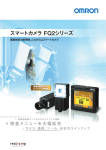
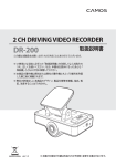
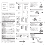
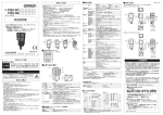
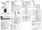
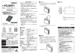
形
FQ□-D30/-D31
スマートカメラ 形FQ□-S用
コードリーダ 形FQ-CR用
文字認識センサ 形FQ2-CH用
タッチファインダ
■タッチペン収納方法
①タッチファインダの放熱をよくするため、次の方向で取り付けてください。
②次のような方向で取り付けないでください。
③通気をよくするため、
タッチファインダの左右と他の機器との間に、
下図に示す間隔以上を空けて取り付けてください。
①
■電源スイッチON方法
本体側面部の電源スイッチカバーを外し、電源スイッチをONに切
り替えてください。
②
ON
OFF
③
取扱説明書
このたびは、本製品をお買い上げいただきまして、まことにありがとうございます。
ご使用に際しては、次の内容をお守りください。
・ 電気の知識を有する専門家がお取り扱いください。
・この取扱説明書をよくお読みになり、十分にご理解のうえ、正しくご使用ください。
・この取扱説明書はいつでも参照できるよう大切に保管してください。
15mm以上
■SDカード挿入方法
15mm以上
本体天面部のSDカードカバーを外し、SDカードを挿入してくださ
い。
・ノイズの影響を避けるため、高圧機器が設置されているパネルに
は取り付けないでください。
・動作環境のノイズを低レベルに抑えるため、
センサやタッチファイン
ダの動力線から10m以上離して取り付けてください。
■各部の名称と機能
(7)
(6)
(3)
(1)
(10)
(11)
(2)
(5)
* 2 1 4 6 9 9 9 - 2 D *
© OMRON Corporation 2010 All Rights Reserved.
(12)
(4)
①
■電源接続
(スイッチングレギュレータ接続時)
(8)
次の電源は推奨電源です
(別売)
(9)
形FQ□-D30
DC電源接続時:DC20.4V∼26.4V
(リップル含む)
バッテリ連続使用可能時間 *
消費電流
絶縁抵抗
周囲温度
周囲湿度
周囲雰囲気
振動
(耐久)
衝撃
(耐久)
保護構造
質量
外形サイズ
材質
付属品
−
DC電源接続時:0.2A以下
リード線一括とケース間:0.5MΩ
(250Vメガにて)
動作時:0∼50℃
保存時:−25∼+65℃
(ただし、
氷結、
結露しないこと)
形FQ□-D31
DC電源接続時:DC20.4V∼26.4V
(リップル含む)
ACアダプタ 形FQ-AC□
(シノ・アメリカン ジャパン
(株)
製)
接続時:AC100V∼240V,50Hz/60Hz
バッテリ接続時:バッテリパック 形FQ-BAT1
(1セル 3.7V)
1.5時間
DC電源接続時:0.2A以下、
バッテリ充電時:0.4A以下
動作時:DIN固定/パネル固定使用時 0∼50℃
バッテリ使用時 0∼40℃
保存時:−25∼+65℃
(ただし、
氷結、
結露しないこと)
動作時、
保存時:各35∼85%RH
(ただし、
結露しないこと)
腐食性ガスのないこと
10∼150Hz 片振幅0.35mm X/Y/Z方向 各8分10回
(上下・左右・前後)
各3回
150m/s2 6方向
IEC60529規格 IP20
約270g
(バッテリ+ハンディストラップ非装着時)
95×85×32.5mm
ケース:ABS
タッチペン、
取扱説明書
(本誌)
*目安時間であり、
保証値ではありません。使用環境、
使用条件等により変化します。
■性能仕様
項目
接続できるセンサ台数
表示 液晶モニタ
バックライト
表示デバイス
画素数
表示色
寿命 *1
輝度調整
自動消灯機能
LED
操作I/F タッチスクリーン 方式
寿命 *2
外部I/F Ethernet
SDカード
バッテリ 充電機能
形FQ□-D31
形FQ□-D30
認識
(センサ切替)
できる最大数:32台、
モニタ表示できる最大数:
8台
3.5インチ TFT カラーLCD
320×240ピクセル
16,777,216色
50,000時間(25℃)
輝度調整機能あり
あり
(設定時間の変更機能あり)
電源ON表示灯
(表示色:緑色)
:POWER
電源ON表示灯
(表示色:緑色)
:POWER
エラー表示灯
(表示色:赤色)
:ERROR
エラー表示灯
(表示色:赤色)
:ERROR
SDカードアクセス表示灯(表示色:黄色)
:SD ACCESS SDカードアクセス表示灯(表示色:黄色)
:SD ACCESS
充電表示灯
(表示灯:オレンジ)
:CHARGE
抵抗膜方式
1,000,000回
100BASE-TX/10BASE-T
SDHC準拠
CLASS 4以上推奨
なし
説明
形S8VS-01524□
(DC24V、0.65A)
M3.5
(締付けトルク:1.0N・m)
16AWG∼22AWG
(長さ5m以下)
電源接続
1.プラスドライバで端子台のネジを緩めます。
(2個)
2.電源ケーブルに圧着端子を取り付けます。
+/−の表示に従い
電源ケーブルをM3ネジ締め付け、固定します。
電源締付けトルク:0.54N・m
DC24V
3.過度にノイズが掛かる環境下では、電源線にフェライ
トコアを取り
付けてください。
(TDK製ZCAT1730-0730相当)
電源線にフェライトコアを装着する場合、
ケーブルは1回巻いてください
■DINレールへの取り付け
1.タッチファインダのスライダを上側に押し込みます。
2.タッチファインダの上側のツメをDINレールに引っ掛けます。
3.タッチファインダの下側のツメが"カチッ"と鳴るまで押し込みます。
2
3
1
3
・DINレール上のタッチファインダの両脇にエンドプレート
(別売)
を
取り付けてください。
・同一DINレール上でタッチファインダの隣に他の機器を取り付け
る場合は、前述の設置間隔を保ってください。
・必ず上側のツメを先にDINレールに引っ掛けてタッチファインダ
を取り付けてください。下側のツメを先にDINレールに引っ掛け
ると、取付け強度が低下します。
取外し方法
1.タッチファインダのスライダを下に引きます。
2.タッチファインダの下側から持ち上げて、DINレールから外します。
2
あり *3
*1 常温常湿にて輝度が半減するまでの目安時間であり、保証値ではありません。バックライト寿命は周囲の温湿度により大きく変化します。低温下、
高温下では寿命は短くなります。
*2 目安回数であり、
保証値ではありません。使用条件により変化します。 *3 タッチファインダ本体の電源スイッチOFF時のみ充電可能です。
■外形寸法
44.5
95
70
11 11 8 3
70
30
1.1
0.5
33
29
ご使用に際してのご承諾事項
インダストリアルオートメーションビジネスカンパニー カスタマサポートセンタ
フリーコール
27
10
15
AC電源コネクタは形FQ□-D31のみ
01 2 0 - 9 19 - 0 6 6
携帯電話・PHSなどではご利用いただけませんので、
その場合は下記電話番号へおかけください。
電話
055-982-5015 (通話料がかかります)
〔技術のお問い合わせ時間〕
■営業時間:8:00∼21:00
■営 業 日:365日
■上記フリ−コ−ル以外のFAシステム機器の技術窓口:
電話
13.5
1
①安全を確保する目的で直接的または間接的に人体を検出する用途に、本製品を使用
しないでください。同用途には、当社センサカタログに掲載している安全センサをご使用
ください。
②下記用途に使用される場合、当社営業担当者までご相談のうえ仕様書などによりご確
認いただくとともに、定格・性能に対し余裕を持った使い方や、万一故障があっても危
険を最小にする安全回路などの安全対策を講じてください。
a)屋外の用途、
潜在的な化学的汚染あるいは電気的妨害を被る用途
またはカタログ、
取扱説明書等に記載のない条件や環境での使用
b)原子力制御設備、
焼却設備、
鉄道・航空・車両設備、
医用機械、
娯楽機械、
安全装置、
および行政機関や個別業界の規制に従う設備
c)人命や財産に危険が及びうるシステム・機械・装置
d)ガス、
水道、
電気の供給システムや24時間連続運転システムなどの
高い信頼性が必要な設備
e)その他、
上記 a) ∼ d) に準ずる、
高度な安全性が必要とされる用途
*上記は適合用途の条件の一部です。当社のベスト、総合カタログ・データシート等最新版
のカタログ、
マニュアルに記載の保証・免責事項の内容をよく読んでご使用ください。
●お問い合わせ先
35.5
使用上の注意
製品が動作不能、誤動作、
または性能・機器への悪影響を防ぐため、以
下のことを守ってください。
1.設置場所について
次のような場所には設置しないでください。
・周囲温度が定格の範囲を越える場所
・温度変化が急激な場所
(結露する場所)
・相対湿度が35∼85%RHの範囲を超える場所
・腐食性ガス、可燃性ガスがある場所
・塵埃、塩分、鉄粉がある場所
・振動や衝撃が直接加わる場所
(レーザ光、
アーク溶接光、紫外光など)
があたる場所
・強い外乱光
・直射日光があたる場所や暖房器具のそば
・水・油・化学薬品の飛沫やみミスト雰囲気がある場所
・強磁界、強電界がある場所
2.電源および接続、配線について
トコアを接続してください。
・過度にノイズが掛かる環境下では規定のフェライ
・スイッチングレギュレータをご使用の際は、
スイッチングレギュレータの
FG端子を接地してください。
・電源ラインにサージがある場合は、使用環境に応じてサージアブソー
バを接続してご使用ください。
・配線後は電源を投入する前に、電源の正誤、負荷短絡などの誤接
続の有無、負荷電流の適否について確認を行ってください。誤配線
などで故障するおそれがあります。
セーブ中のデータが破損します。
・次のような場合は電源を切らないでください。
-各種データを内部メモリにセーブ中
-各種データをSDカードにセーブ中
・液晶ディスプレイパネルは精密な技術でつくられておりますが、
ごくわ
ずかな画素欠陥がある場合があります。
これは液晶パネルの構造に
よるもので故障ではありません。
項目
許容電源電圧範囲
27.9
以下に示すような項目は安全を確保する上で必要なことですので必ず
守ってください。
1.設置環境について
・引火性、爆発性ガスの環境では使用しないでください。
・操作や保守の安全を確保するため、高電圧機器や動力機器から離
して設置してください。
・通気孔を塞がないように本体を設置してください。
2.電源および配線について
・指定した電源電圧で使用してください。
・配線は指定サイズの圧着端子を付けてください。撚り合わせただけ
の電線を直接電源端子台に接続しないでください。
・本製品は他の商品と一緒にせず、単独の電源で使用してください。
・電源線の長さはできるだけ短くなるように配線してください。
・定格電圧を超える電圧や交流電源を使用しないでください。
・電源の逆接続はしないでください。
・高圧線、動力線と当製品の配線は別配線としてください。同一配線
あるいは同一ダクトにすると誘導を受け、誤動作あるいは破損の原
因になることがあります。
・電源は、高電圧が発生しないように対策(安全超低電圧回路)
され
ている直流電源装置から供給してください。
・システム全体でUL認定が必要なときは、ULクラスⅡの直流電源装置
をお使いください。
・FQ□-D31を使用される場合は、
スイッチングレギュレータとACアダプ
タ
(FQ-AC□)
を同時に接続して使用しないでください。
・取付けネジは、本書に記載している規定のトルクで締め付けてください。
・圧着端子は指定サイズのものを使用してください。
・ケーブル、電源線を着脱するときは必ず本体の電源を切ってください。
・電池が漏液したり異臭がする時には直ちに電源を切ってください。漏
液した電解液に引火し、発煙、破裂、発火の原因となります。
・電池の使用、充電、保管時に異臭を発したり、発熱をしたり、変色、
変形その他今までと異なる場合、機器より取り出し、使用しないで下
さい。
そのまま使用すると、電池が発熱、発煙、破裂、発火する原因
になる恐れがあります。
3.その他
・原子力や、人命に関わる安全回路には使用しないでください。
・本製品を分解、修理、改造、加圧変形、焼却したりしないでください。
・廃棄するときは、産業廃棄物として処理してください。
・専用のセンサ
(形FQ□-S、形FQ-CR)、バッテリ
(形FQ-BAT1)、
ACアダプタ
(形FQ-AC□)
を使用してください。専用品以外を使用
すると発火や燃焼、誤動作や故障の原因になります。
・万一、異常を感じたときは、
すぐに使用を中止し、電源を切った上で、
当社支店・営業所までご相談ください。
・落下や強い衝撃を与えないでください。
・FQ□-D31を固定して使用される場合は、バッテリ
(FQ-BAT1)
を
取りはずしてご使用ください。バッテリを入れたまま定格温度を超える
と保護回路が作動し停止する可能性があります。
項目
推奨電源
外部電源端子台ネジ
推奨電線サイズ
■定格/性能
12.1
安全上の要点
*形FQ□-D31にのみ対応します。
20
リチウムイオンバッテリを内蔵しており、発火、破裂
、燃焼により重度の重症が起こる恐れがあります。
分解、加圧変形、100℃以上の加熱、焼却はし
ないでください。
85
警告
52.9
● 警告表示
35.5
警告
正しい取扱いをしなければ、この危険のため
に、軽傷・中程度の傷害を負ったり万一の
場合には重傷や死亡に至る恐れがあります
。また、同様に重大な物的損害をもたらす
恐れがあります。
説明
POWER
タッチファインダの電源が投入されると緑色で点灯します。
ERROR
エラーが発生すると赤色で点灯します。
SD ACCESS SDカードが挿入されると黄色で点灯します。SDカードアクセス時に黄色で点滅します。
CHARGE * バッテリを充電中にオレンジ色で点灯します。
(2)
液晶モニタ/タッチパネル
設定メニューや計測結果、
カメラで撮影した画像を表示します。
タッチパネルを操作することで、
カメラやタッチフ
ァインダの設定ができます。
(3)
SDカード
SDカードを差し込みます。
本カバーの内側にバッテリ装着部があります。バッテリを装着または脱着するとき、
このカバーを取り外してください。
(4) バッテリカバー *
タッチファインダの電源をON/OFFするときに使用します。
(5)
電源スイッチ
タッチペンを使わないときに格納できます。
(6) タッチペンホルダ
タッチパネルを操作するときに使用します。
タッチファインダを使用する前にタッチペンのストラップをストラップホ
(7) タッチペン
ルダに結びつけてください。
DC電源を接続するときに使用します。
(8)
DC電源コネクタ
タッチファインダをDINレールに固定するときに使用します。
(9) スライダ
イーサネットケーブルを使用して、
タッチファインダとセンサを接続するときに使用します。
(10) イーサネットポート
ストラップを取り付けるためのホルダです。
(11) ストラップホルダ
ACアダプタを接続するときに使用します。
(12) AC電源コネクタ *
30
82
17.3
● 警告表示の意味
名称
動作表示灯
19.2
安全上のご注意
No.
(1)
23.8 14
米国カリフォルニア州過塩素酸塩規制について:
この製品はカリフォルニア州法で規制されている過塩素酸塩を含
むリチュームバッテリーですので、
この州法への対応をしてください。
詳しくは下記URLをご覧ください。
www.dtsc.ca.gov/hazardouswate/perchlorate/
(単位:mm)
055-977-6389
(通話料がかかります)
〔営業のお問い合わせ時間〕
■営業時間:9:00∼12:00/13:00∼17:30 (土・日・祝祭日は休業)
■営 業 日:土・日・祝祭日/春期・夏期・年末年始休暇を除く
●FAXによるお問い合わせは下記をご利用ください。
カスタマサポートセンタ お客様相談室 FAX 055-982-5051
●その他のお問い合わせ先
納期・価格・修理・サンプル・仕様書は貴社のお取引先、
または貴社担当オムロン営業員にご相談ください。
B q 2009年 10月
Model
FQ□-D30/-D31
■ Procedure for storing the touch pen
1)Install the Touch Finder in the following orientation to allow sufficient heat
dissipation.
2) Do not mount it in the following orientations.
3)To improve ventilation, leave space on both sides of the Touch Finder. The
distance between the Touch Finder and other devices should be at least that
shown in the following diagram.
1)
■ Procedure for switching on the power switch
Remove the power switch cover from the side of the unit, and
switch the power switch to ON.
2)
Touch Finder for FQ□-S Smart Camera
FQ-CR Code Reader
Optical Character Recognition Sensor for FQ2-CH
(1)
Lights red when an error occurs.
SD ACCESS
Lights yellow when an SD card is inserted. Flashes yellow when the SD card is being accessed.
CHARGE *
Lights orange when the Battery is charging.
(2)
LCD/touch panel
This displays the setting menu, measurement results, and the image captured by the camera. The touch panel
can be operated to configure camera and Touch Finder settings.
(3)
SD card slot
An SD card can be inserted.
(4)
Battery cover*
The Battery is mounted behind this cover. Remove the cover when mounting or removing the Battery.
(5)
Power supply switch
Used to turn the power supply to the Touch Finder ON and OFF.
(6)
Touch pen holder
The touch pen can be stored in here when it is not being used.
(7)
Touch pen
Used to operate the touch panel. Before using the Touch Finder, tie the touch pen strap to the strap holder.
(8)
DC power supply connector
Used to connect a DC power supply.
(9)
Slider
Used to mount the Touch Finder to a DIN Track.
(10)
Ethernet port
Used when connecting the Touch Finder to the Sensor with an Ethernet cable.
(11)
Strap holder
(12)
AC power supply connector*
This is a holder for attaching the strap.
Used to connect the AC adapter.
Item
Power supply voltage
Output current
Recommended
Power Supply
Description
External power supply
terminal screws
M3.5 (tightening torque: 1.0 N·m)
Recommended power
line wire size
AWG16 to AWG22
(length of 5 m max.)
24 VDC (21.6 to 26.4 V)
2.5 A min.
S8VS-06024□(24 VDC, 2.5 A)
Connecting the Power Supply
1. Loosen the two terminal screws using a Phillips screwdriver.
2. Attach crimp terminals to the power lines.
Secure the positive and negative lines as indicated using M3
screws. Power supply tightening torque: 0.54 N·m
* Applicable to the FQ-D31 only.
■ Ratings/Performance
24 VDC
Item
FQ□-D30
FQ□-D31
Allowable power voltage range
DC power connection: 20.4 to 26.4 VDC (including
ripple)
When a DC power supply is connected:
20. 4 V to 26.4 V DC (including ripple)
When the FQ-AC□ AC adapter (manufactured by SinoAmerican Japan Co., Ltd) is connected:
100 V to 240 V AC, 50/60 Hz
When a battery is connected:
FQ-BAT1 battery pack (1 cell, 3.7 V)
Continuous operation on Battery* −
1.5 h
Current consumption
DC power connection: 0.2 A MAX
DC power connection: 0.2 A MAX Charging battery: 0.4A MAX
Insulation resistance
Ambient temperature
Between all lead wires and case: 0.5 MΩ (at 250 V)
Operating: 0 to 50°C
Storage: −25 to 65°C
(with no icing or condensation)
Ambient humidity
Operating: 0 to 50°C when mounted to DIN Track or panel
0 to 40°C when operated on a Battery
Storage: −25 to 65°C
(with no icing or condensation)
Operating and storage: 35% to 85% (with no condensation)
Ambient atmosphere
No corrosive gas
3. In environments where there is excessive noise, attach a ferrite core to
the power supply cable (ZCAT1730-0730 from TDK or the equivalent).
When you attach the ferrite core to the power
supply cable, wrap the cable only one time.
■ Mounting to DIN Track
1. Press the slider on the Touch Finder to the top.
2. Hook the clip at the top of the Touch Finder on to the DIN Track.
3. Press the Touch Finder onto the DIN Track until the bottom clip
clicks into place.
Vibration resistance (destruction) 10 to 150 Hz, single amplitude: 0.35 mm, X/Y/Z directions 8 min each, 10 times
150 m/s2 3 times each in 6 direction (up, down, right, left, forward, and backward)
Shock resistance (destruction)
Degree of protection
Weight
IEC 60529 IP20
270 g max. (without battery or hand strap)
Dimensions
95 × 85 × 32.5 mm
Materials
Case: ABS
Accessories
Touch Pen, Instruction Manual (This Instruction Sheet)
2
3
1
3
* This value is only a guideline. No guarantee is implied. The value will be affected by operating conditions.
■ Performance specifications
Item
Number of connectable sensors
Display
LCD
Display device
Pixels
Display colors
Backlight Life expectancy*1
Brightness
adjustment
Screen saver
Indicators
Operation
interface
Touch
screen
External
interface
Ethernet
Battery
Method
Life expectancy*2
SD card slot
Charging function
FQ□-D30
FQ□-D31
Number of sensors that can be recognized (switched): 32, number of sensors that can displayed on monitor: 8
3.5-inch TFT color LCD
320 × 240
16,777,216
50,000 hours at 25°C
Provided
Provided (a function for changing the time setting is available)
Power indicator (color: green): POWER
Power indicator (color: green): POWER
Error indicator (color: red): ERROR
Error indicator (color: red): ERROR
SD card access indicator (color: yellow):
SD card access indicator (color: yellow):
SD ACCESS
SD ACCESS
Charge indicator (color: orange): CHARGE
Resistance film
1,000,000 operations
100Base-TX/10Base-T
SDHC-compliant, Class 4 or higher recommended
Not available
Available*3
*1 This is a guideline for the time required for the brightness to diminish to half the initial brightness at room temperature and humidity. No
guarantee is implied. The life of the backlight is greatly affected by the ambient temperature and humidity. It will be shorter at lower or
higher temperatures.
*2 This value is only a guideline. No guarantee is implied. The value will be affected by operating conditions.
*3 Charging is possible only when the power switch of the Touch Finder unit is OFF.
■ Dimensions
33
29
Suitability for Use
THE PRODUCTS CONTAINED IN THIS SHEET ARE NOT SAFETY RATED.
THEY ARE NOT DESIGNED OR RATED FOR ENSURING SAFETY OF
PERSONS, AND SHOULD NOT BE RELIED UPON AS A SAFETY
COMPONENT OR PROTECTIVE DEVICE FOR SUCH PURPOSES.
Please refer to separate catalogs for OMRON's safety rated products.
NEVER USE THE PRODUCTS FOR AN APPLICATION INVOLVING
SERIOUS RISK TO LIFE OR PROPERTY WITHOUT ENSURING THAT THE
SYSTEM AS A WHOLE HAS BEEN DESIGNED TO ADDRESS THE RISKS,
AND THAT THE OMRON PRODUCT IS PROPERLY RATED AND
INSTALLED FOR THE INTENDED USE WITHIN THE OVERALL
EQUIPMENT OR SYSTEM.
See also Product catalog for Warranty and Limitation of Liability.
70
30
0.5
1.1
27
10
1
Take all necessary steps to determine the suitability of the product for the
systems, machines, and equipment with which it will be used.
Know and observe all prohibitions of use applicable to this product.
95
70
11 11 8 3
15
Removal Procedure
1. Pull down on the slider on the Touch Finder.
2. Lift the Touch Finder at the bottom and remove it from the
DIN Track.
OMRON shall not be responsible for conformity with any standards, codes, or
regulations that apply to the combination of the products in the customer's
application or use of the product.
44.5
13.5
· Attach End Plates (sold separately) on the sides of the Touch
Finder on the DIN Track.
· If other devices will be installed next to the Touch Finder on the
same DIN Track, make sure that sufficient space is kept
between the devices as indicated previously.
· Always hook the clip at the top of the Touch Finder on the DIN
Track first. If the lower clip is hooked on first, the Touch Finder
will not be mounted very securely.
2
EUROPE
OMRON EUROPE B.V. Sensor Business Unit
Carl-Benz Str.4, D-71154 Nufringen Germany
Phone:49-7032-811-0 Fax: 49-7032-811-199
NORTH AMERICA
OMRON ELECTRONICS LLC
One Commerce Drive Schaumburg,IL 60173-5302 U.S.A.
Phone:1-847-843-7900 Fax : 1-847-843-7787
ASIA-PACIFIC
OMRON ASIA PACIFIC PTE. LTD.
No. 438A Alexandra Road #05-05-08(Lobby 2),
Alexandra Technopark, Singapore 119967
Phone : 65-6835-3011 Fax :65-6835-2711
CHINA
OMRON(CHINA) CO., LTD.
Room 2211, Bank of China Tower,
200 Yin Cheng Zhong Road,
PuDong New Area, Shanghai, 200120, China
Phone : 86-21-5037-2222 Fax :86-21-5037-2200
27.9
Precautions for Correct Use
Observe the following to prevent failure, malfunctioning, and adverse
effects on performance and the device.
1. Installation site
Do not install in the following locations:
· Locations where the ambient temperature exceeds the rated
temperature range.
· Locations subject to sudden temperature changes (where
condensation will form).
· Locations where the relative humidity is below or above 35 to 85% RH.
· Locations where there are corrosive or flammable gases.
· Locations where there is dust, salt, or iron powder.
· Locations where the device will be subject to direct vibration or
shock.
· Locations where there is strong scattered light (laser light, arc
welding light, ultraviolet light, etc.)
· Locations exposed to direct sunlight or next to a heater.
· Locations where there is splashing or spraying of water, oil, or chemicals.
· Locations where there is a strong electrical or magnetic field.
2. Power, connections, and wiring
· In environments subject to excessive noise, connect the specified
ferrite core.
· When using a switching regulator, ground the FG pin of the
switching regulator.
· If there are surges on your power line, connect a surge absorber as
appropriate for your conditions of use.
· Before turning on the power after the wiring is completed, verify that
the power is correct, that there are no incorrect connections such as a
shorted load circuit, and that the load current is suitable. Incorrect
wiring may cause damage and failures.
· In the following situations, do not turn off the power. Data being
saved will be corrupted.
-Various data are being saved to the internal memory.
-Various data are being saved to an SD card.
· The LCD display panel is manufactured by precision technology;
however, there may be a few faulty picture elements. This is due to
the structure of the LCD panel and is not a product failure.
Lights green when power is supplied to the Touch Finder.
ERROR
20
Always follow the rules below to ensure safety.
1. Installation environment
· Do not use in a location where there is flammable or explosive gas.
· To ensure safe operation and maintenance, install away from
high-voltage equipment and power equipment.
· Install the unit so that the vents are not blocked.
2. Power and cable connections
· Use the specified power supply voltage.
· Use the specified size of crimp terminals for wiring connections.
Do not connect wires that have been simply twisted together
directly to the power supply or terminal block.
· Use a separate power supply. Do not share the power supply with
other devices.
· Keep the power supply cable as short as possible.
· Do not use a voltage that exceeds the rated voltage, and do not use
an AC power supply.
· Do not reverse the polarity of the power connection.
· Wire this product separately from the wiring of high-voltage wires
and power wires. If wired together or in the same conduit, induction
may occur and cause malfunctioning or damage.
· Supply power from a DC power supply for which measures have been
applied to prevent high voltages (e.g., a safety overvoltage circuit).
· If UL certification is required for the overall system, use a UL Class
II DC power supply.
· When using the FQ-D31, do not use with the switching regulator
and AC adapter (FQ-AC□) simultaneously connected.
· Tighten the mounting screws to the torque specified in these instructions.
· Use the specified size of crimp terminals.
· Always turn OFF the power supply before connecting or
disconnecting cables or the power supply wiring.
· Turn OFF the power supply immediately if the battery leaks or
produces an odor. Electrolyte leaked from the battery may ignite,
possibly causing smoke, rupture, or fire.
· If, during usage, charging, or storage, the battery produces an odor, heats,
becomes discolored, becomes misshapen, or exhibits any other unusual
conditions, remove it and do not use it. Continuing to use such a battery
may result in the battery heating, smoking, rupturing, or igniting.
3. Other Rules
· Do not use in safety circuits for atomic energy or that are critical
for human life.
· Do not attempt to disassemble, deform by pressure, incinerate,
repair, or modify this product.
· When disposing of the product, treat as industrial waste.
· Use the special sensor (FQ□-S, FQ-CR), battery (FQ-BAT1), and
AC adapter (FQ-AC□). Using other than the specified devices may
cause ignition, burning, malfunctioning, or failure.
· If you notice an abnormal condition, stop using the unit
immediately, turn off the power, and consult your dealer.
· Do not drop or subject to shock.
· If the FQ-D31 will be secured, remove the battery (FQ-BAT1).
If the rated temperature is exceeded with the battery inserted, the
protective circuit may activate and stop the unit.
POWER
52.9
Precautions for Safe Use
The following power supply is recommended (option)
35.5
The Touch Finder contains a lithium ion battery. There
is danger of severe injury due to fire, explosion, or
combustion. Never disassemble the Touch Finder,
deform it by pressure, or heat it to 100°C or higher.
Operation
indicators
(9)
30
82
17.3
WARNING
(1)
■ Power connection
(when a switching regulator is connected)
Description
19.2
● Warning Symbols
Name
(8)
14
WARNING
Indicates a potentially hazardous
situation which, if not avoided,
could result in death or serious
injury. Additionally, there may be
severe property damage.
No.
(10)
(11)
(2)
(5)
(12)
(4)
23.8
● Keys to Warning Symbols
(7)
(6)
(3)
© OMRON Corporation 2010 All Rights Reserved.
SAFETY PRECAUTIONS
Remove the SD card cover from the top of the unit and insert
the SD card.
■ Part Names and Functions
The following notice applies only to products that carry the CE mark:
Notice:
This is a class A product. In residential areas it may cause radio
interference, in which case the user may be required to take adequate
measures to reduce interference.
California regulations concerning perchlorate:
This product is a lithium battery that contains perchlorate, which
is regulated by the State of California. Please comply with these
regulations. For details see the following URL:
www.dtsc.ca.gov/hazardouswaste/perchlorate/
■ Procedure for inserting an SD card
15 mm min.
35.5
TRACEABILITY INFORMATION:
Representative in EU:
Manufacturer:
Omron Europe B.V.
Omron Corporation,
Wegalaan 67-69
Shiokoji Horikawa, Shimogyo-ku,
2132 JD Hoofddorp,
Kyoto 600-8530 JAPAN
The Netherlands
Ayabe Factory
3-2 Narutani, Nakayama-cho,
Ayabe-shi, Kyoto 623-0105 JAPAN
15 mm min.
• To prevent interference by noise, do not mount the Touch Finder on panels
which contain high-voltage devices.
• To keep the level of noise from the surrounding environment to a minimum,
install the Sensor and Touch Finder unit at least 10 m away from their
power lines.
12.1
Thank you for selecting OMRON product. This sheet primarily describes precautions required in installing and
operating the product.
Before operating the product, read the sheet thoroughly to
acquire sufficient knowledge of the product. For your convenience, keep the sheet at your disposal.
OFF
3)
85
INSTRUCTION SHEET
ON
The AC power connector is only on the FQ-D31.
(Unit: mm)
OMRON Corporation
D o O CT, 2 0 0 9